EP0823615A2 - Light receiving point sensing device - Google Patents
Light receiving point sensing device Download PDFInfo
- Publication number
- EP0823615A2 EP0823615A2 EP97113154A EP97113154A EP0823615A2 EP 0823615 A2 EP0823615 A2 EP 0823615A2 EP 97113154 A EP97113154 A EP 97113154A EP 97113154 A EP97113154 A EP 97113154A EP 0823615 A2 EP0823615 A2 EP 0823615A2
- Authority
- EP
- European Patent Office
- Prior art keywords
- light receiving
- receiving point
- light
- photoelectric conversion
- sensing device
- Prior art date
- Legal status (The legal status is an assumption and is not a legal conclusion. Google has not performed a legal analysis and makes no representation as to the accuracy of the status listed.)
- Withdrawn
Links
Images


Classifications
-
- G—PHYSICS
- G01—MEASURING; TESTING
- G01C—MEASURING DISTANCES, LEVELS OR BEARINGS; SURVEYING; NAVIGATION; GYROSCOPIC INSTRUMENTS; PHOTOGRAMMETRY OR VIDEOGRAMMETRY
- G01C15/00—Surveying instruments or accessories not provided for in groups G01C1/00 - G01C13/00
- G01C15/002—Active optical surveying means
- G01C15/004—Reference lines, planes or sectors
- G01C15/006—Detectors therefor
Landscapes
- Physics & Mathematics (AREA)
- Engineering & Computer Science (AREA)
- General Physics & Mathematics (AREA)
- Radar, Positioning & Navigation (AREA)
- Remote Sensing (AREA)
- Length Measuring Devices By Optical Means (AREA)
- Photovoltaic Devices (AREA)
Abstract
Four pairs of right-angled-triangular solar cell panels
21a, 21b, ... are arranged in series along a longitudinal
direction of a columnar device body in such a manner that two
solar cell panels forming each pair are adjacent at their
hypotenuses to each other, thereby forming a light-receiving
part 2. Output signals corresponding to amounts of light
reception of each pair of solar cell panels are inputted to
corresponding operating unit 80. Each operating unit 80
operates a difference between an amount of light reception
of one solar cell panel forming the pair and an amount of light
reception of the other solar cell panel. Based on the
difference, a microprocessor 84 detects a deviation of an
actual light receiving point with respect to a reference light
receiving point 2a. The microprocessor 84 numerically
indicates the detected deviation on a liquid crystal
indicating panel 3 and transfers the detected deviation to
an external computer or the like through an I/O interface unit
9.
Description
This invention relates to a light receiving point
sensing device for use in measurements of horizontal or
vertical displacements of buildings or the like, leveling
controls of earthmovers, land surveys by leveling and the like,
and particularly relates to a light receiving point sensing
device which receives a reference light beam and detects a
position of an object to be measured relative to its light
receiving point.
Conventionally, in leveling controls over blades of
bulldozers and the like, a rotating laser for making a rotary
scanning within a reference plane with the use of a laser light
is placed and a reference laser light projected from the
rotating laser is received by a light receiving point sensing
device mounted on an earthmover such as a bulldozer. A blade
of the bulldozer is controlled in position by using a light
receiving point of the sensing device as a reference level.
As an example of light receiving point sensing devices
of such kind, there is known a device using a batch of optical
fibers, as disclosed in Japanese Patent Publication Gazette
No. 3-18122. In this device, a laser light projected from
the rotating laser is transferred from light-receptive
surfaces arranged on the periphery of a cylindrical body of
the device to a photoelectric conversion element inside the
device body through the batch of optical fibers. The device
is structured such that an area of the light-receptive
surfaces and the number of optical fibers are gradually
increased or decreased in a vertical direction. Under this
structure, since an amount of light reception of the
photoelectric conversion element changes with vertical
shifts of the laser-light receiving point on the periphery
of the device body, the laser-light receiving point can be
detected based on the amount of light reception.
In the conventional light receiving point sensing device
above-mentioned, however, the light-receptive surfaces are
arranged discontinuously on the periphery of the device body
so that the gradual change in area of the light-receptive
surfaces is comparatively rough. In addition, the optical
fibers cause attenuation of amounts of light and the like.
Therefore, the above device provides an inconvenience that
the detection of a light receiving point based on the amount
of light reception cannot be enhanced in accuracy.
The present invention has been made in view of the above
problem and has its object of improving the structure of a
light-receiving part thereby providing an enhanced accuracy
of detection of a light receiving point sensing device.
To attain the above object, the present invention is
directed to a light receiving point sensing device having:
light-receiving means which is placed on an object to be
measured in the form of extending along a direction of locating
the object and receives a reference light beam; and detecting
means for detecting a deviation in the direction of locating
the object of an actual light receiving point with respect
to a reference light receiving point preset in the light-receiving
means. The light-receiving means comprises a pair
of photoelectric conversion panels composed of: a first
photoelectric conversion panel having the form that an area
of its light-receptive surface gradually increases from one
side of the direction of locating the object toward the other
side thereof; and a second photoelectric conversion panel
which is placed at a position adjacent to the first
photoelectric conversion panel in a direction orthogonal to
the direction of locating the object and has the form that
an area of its light-receptive surface gradually decreases
from one side of the direction of locating the object toward
the other side thereof. The detecting means detects a
deviation of the actual light receiving point with respect
to the reference light receiving point based on a signal
outputted from the first photoelectric conversion panel and
a signal outputted from the second photoelectric conversion
panel.
Under the above structure, an amount of light received
by the first photoelectric conversion panel and an amount of
light received by the second photoelectric conversion panel
each change with the shift of the actual light receiving point
in the direction of locating the object to be measured.
Accordingly, based on the changes in the amounts of light,
the actual light receiving point can be detected with higher
accuracy as compared with the conventional case. For example,
when the actual light receiving point is shifted from one side
in the direction of locating the object to the other side
therein, the first photoelectric conversion panel gradually
increases its amount of light reception with the shift of the
light receiving point while the second photoelectric
conversion panel gradually decreases its amount of light
reception with the shift of the light receiving point. Then,
based on signals outputted from the first and second
photoelectric conversion panels respectively, a shift in the
actual light receiving point is detected by the detecting
means. At this time, even if an amount of change in each signal
value corresponding to the shift in the actual light receiving
point is comparatively small, each signal value can be
subtracted or divided by the detecting means so that the
operated amount of change in the signal value are sufficiently
amplified. Accordingly, it becomes possible to detect a shift
in the light receiving point with higher accuracy as compared
with the conventional case. This provides an enhanced accuracy
of detecting a light receiving point.
The light-receiving means preferably comprises at least
two pairs of photoelectric conversion panels, the pairs are
aligned along the direction of locating the object to be
measured.
When the pairs of photoelectric conversion panels are
aligned along the direction of locating the object to be
measured, respective degrees of changes in light-receptive
surface area of the respective photoelectric conversion
panels can be set sufficiently large even if the light-receiving
means is formed so as to have a long length in the
direction of locating the object to be measured. This allows
the light-receiving means to have a long length in the
direction of locating the object without decreasing its
accuracy of detecting a light receiving point. Accordingly,
the reference light beam can be received comparatively with
ease.
It is preferable that the pair of photoelectric
conversion panels are each formed in a right-angled triangle
and are placed to be adjacent at hypotenuses to each other.
Under the above structure, with the shift of a light
receiving point in the direction of locating the object to
be measured, a light-receptive surface area of one of adjacent
two photoelectric conversion panels is sure to gradually
increase while a light-receptive surface area of the other
is sure to gradually decrease. In other words, output signals
from the photoelectric conversion panels change in response
to a deviation of the light receiving point from the reference
light receiving point. Accordingly, detection of the light
receiving point by the detecting means can be facilitated.
Further, the photoelectric conversion panels can be arranged
without wasting space.
The outline of the light-receptive surface of the
photoelectric conversion panel is preferably formed through
masking with the use of light-tight material.
Under the structure, the outline of the light-receptive
surface of the photoelectric conversion panel can be formed
in an arbitrary form with ease. This facilitates the formation
of the light-receiving means.
The detecting means is preferably configured to detect
a deviation of the actual light receiving point with respect
to the reference light receiving point based on a subtraction
between a signal outputted from the first photoelectric
conversion panel and a signal outputted from the second
photoelectric conversion panel.
Under the configuration, the detecting means can detect
a deviation of the actual light receiving point with respect
to the reference light receiving point based on a difference
between an amount of light reception of the first
photoelectric conversion panel and an amount of light
reception of the second photoelectric conversion panel.
Accordingly, even if a change in the amount of light reception
of each photoelectric conversion panel due to a shift of the
light receiving point is comparatively small, a change in the
difference between the amounts of light reception of the first
and second photoelectric conversion panels can be
sufficiently large. This enables a high-accuracy detection
of a change in light receiving point.
It is preferable that the light receiving point sensing
device of the present invention further comprises: a reference
point indicating line provided with respect to the reference
light receiving point; a scale calibrated from the reference
light receiving point toward both sides in the direction of
locating an object to be measured; and indicating means for
numerically indicating a deviation detected by the detecting
means.
Under the above structure, when a light receiving point
is marked on an object to be measured, a deviation of the light
receiving point with respect to the reference light receiving
point can be read with ease, and the marking can be made with
ease according to the read value with reference to graduations
of the scale. This eliminates the need for aligning the light
receiving point sensing device with the reference light beam
by moving the light receiving point sensing device thereby
increasing workability, and eliminates a detection error due
to the alignment thereby increasing detection accuracy.
It is preferable that the light receiving point sensing
device of the invention further comprises communicating means
for transmitting a deviation detected by the detecting means
to external equipment.
Under the above structure, since a detected result can
be transmitted to external equipment such as a computer, this
eliminates the need for a measurer to read the detected result.
Further, if the light receiving point sensing device is
attached to a vibrating object to be measured to detect
amplitudes of the object, amplitude measurements can be made
with ease. Furthermore, since a detected result can be
transmitted to an external memory for automatic storage, this
makes it possible to store displacements of an object to be
measured without human intervention for a long time.
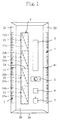
Fig. 1 is a front view showing the structure of a light
beam sensor according to an embodiment of the present
invention.
Fig. 2 is a block diagram showing the structure of a
detecting means.
Fig. 3 is a diagram showing the structure of a
photoelectric conversion panel according to another
embodiment of the invention.
Fig. 4 is a schematic diagram showing the principle of
detection of a light receiving point.
Fig. 5 is a diagram showing an application of a light
receiving point sensing device of the invention to an
electronic level rod.
Description will be made below about embodiments of the
present invention with reference to the drawings.
Fig. 1 shows an application of a light receiving point
sensing device of the present invention to a light beam sensor
100 used for land surveys by leveling and the like. In the
figure, reference numeral 1 denotes a resin-made device body
formed in a column, reference numeral 2 denotes a light-receiving
part as a light-receiving means for receiving a
laser light projected from an unshown rotating laser, and
reference numeral 3 denotes an indicating part for numerically
indicating a deviation between a reference light receiving
point 2a preset in the light-receiving part 2 and an actual
light receiving point of the laser light. Reference numeral
4 denotes a scale serving as an index for marking an object
surface to be measured, reference numeral 5 denotes a bubble
tube for indicating the degree of tilt of the device body 1
with respect to a perpendicular direction, reference numeral
6 denotes a reset switch for resetting the indicated value
on the indicating part 3 to "0", and reference numeral 7
denotes an operating switch of the light beam sensor 100.
The device body 1 has a horizontally sectional form of
a trapezoid and forms a surface corresponding to the lower
base of the trapezoid (back surface in the figure) into a
reference surface 1a to be made contact with an object surface
to be measured. The light-receiving part 2, the indicating
part 3 and the like are placed on a first surface 1b (front
surface in the figure) opposite to the reference surface 1a.
The scales 4, 4 are provided on a second surface 1c and a third
surface 1d which correspond to both the hypotenuses of the
trapezoid, respectively.
The light-receiving part 2 is placed on the first
surface 1b of the device body 1 so as to extend in a
longitudinal direction (a vertical direction in Fig. 1:
hereinafter, referred to as a vertical direction) and has the
reference light receiving point 2a set at its central position
in the vertical direction. The light-receiving part 2 is
composed of a plurality of solar cell panels (photoelectric
conversion panels) 21a, 21b, 22a, 22b, ... each having the same
form of a right-angled triangle. The solar cell panels 21a,
21b, 22a, 22b, ... are arranged such that each two forming a
pair out of them are placed side by side in a relation adjacent
at their hypotenuses to each other. Four pairs of solar cell
panels in total are arranged such that two pairs of solar cell
panels are arranged on each of upper and lower sides from the
reference light receiving point 2a. Each of the solar cell
panels 21a, 21b, ... outputs an electric signal corresponding
to its amount of light reception.
The indicating part 3 is a liquid crystal display panel
having a backlight and numerically indicates a vertical
deviation between an actual light receiving point on the
light-receiving part 2 and the reference light receiving point
2a with high accuracy (for example, in tenths of one
millimeter). The scales 4, 4 are formed on the second and third
surfaces 1c, 1d of the device body 1 respectively so as to
extend in parallel with the light receiving part 2 and indicate
in millimeters upward and downward distances from respective
reference point indicating lines 41, 41 marked on the right
and left sides of the reference light receiving point 2a of
the light-receiving part 2.
The bubble tube 5 encapsulates a small amount of air in
a transparent capsule together with a liquid such as alcohol
and is for observing the air in a bubble form. The air bubble
moves in the transparent capsule according to a tilt of the
device body 1, thereby indicating the degree of tilt of the
device body 1.
Fig. 2 shows a detecting means 2 for detecting a vertical
deviation between an actual light receiving point and the
reference light receiving point 2a based on input signals from
the light-receiving part 2. In the figure, reference numerals
80, 80, ... denote respective operating units provided in
correspondence to respective pairs 21, 22, ... of solar cell
panels, reference numerals 81, 81, ... denote filter amplifiers
which are contained in the operating units 80, 80, ... and input
signals from the solar cell panels 21a, 21b, ... respectively,
reference numerals 82, 82, ... denote A/D converters which are
contained in the operating units, and reference numerals 83,
83, ... denote subtracters which are contained in the operating
units. Reference numeral 84 denotes a microprocessor for
receiving signals from the operating units 80, 80, ..., and
reference numeral 9 denotes an I/O interface unit as a
communicating means.
The operating units 80, 80, ... each output a signal
corresponding to a difference between amounts of light
reception of the first solar cell panel 21a, 22a, ... (left side
in Fig. 2) and the second solar cell panel 21b, 22b, ... (right
side in Fig. 2) of the corresponding pair 21, 22, ... of solar
cell panels to the microprocessor 84. The microprocessor 84
detects a vertical deviation between an actual light receiving
point and the reference light receiving point 2a on the light
receiving part 2 based on the input signals.
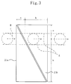
For example, as shown in an imaginary line A in Fig. 3,
when a beam spot B of a laser light projected from the rotating
laser horizontally passes through the pair 21 of solar cell
panels along a line divided at a ratio of a:b from the panel
top ends so as to traverse from left to right, a ratio of
amounts of light reception received by left and right panels
21a, 21b forming the pair 21 is a:b. Electric signal (Ia, Ib)
proportional to the corresponding amounts of light reception
are outputted from the solar cell panels 21a, 21b and are then
amplified by the filter amplifiers 81, 81, respectively. The
amplified electric signals are converted into digital signals
by the A/ D converters 82, 82 respectively and are then
subtracted through the subtracter 83. The subtracted result
(Ia - Ib) is inputted to the microprocessor 84. The
microprocessor 84 accurately locates a vertical light
receiving point thereby accurately detecting a deviation
between the light receiving point and the reference light
receiving point 2a.
The deviation, detected in the above manner, between the
light receiving point and the reference light receiving point
2a is numerically indicated on the indicating part 3 and is
transferred from the I/O interface unit 9 to external
equipment, such as a personal computer and a memory, connected
to the light beam sensor 100, through an unshown communication
cable.
Next, description is made about a method of using the
light beam sensor 100 of the above embodiment for land surveys
by leveling and about operations and effects of the light beam
sensor 100 used in the method.
First, a measurer pushes the operating switch 7 to put
the light beam sensor 100 into an operating mode, and moves
the device body 1 up and down with the reference surface 1a
made contact with an object surface to be measured while
keeping the device body 1 in a vertical position, thereby
allowing the light beam sensor 100 to receive a reference laser
light projected to the rotating laser. Briefly, the measurer
moves the device body 1 up and down until the indicating part
3 provides a numeric indication. Then, the measurer slightly
rotates the device body 1 around the reference light receiving
point 2a with reference to the position of an air bubble in
the bubble tube 5 to correctly orient it in a perpendicular
direction.
In this state, while keeping the device body 1 pushed
on the object surface to be measured, the measurer marks points
on the object surface which are distant by the indicated value
on the indicating part 3 from the reference spot indicating
lines 41, 41 in accordance with graduations of the scale 4.
In this manner, the reference level point can be correctly
marked on the object surface to be measured.
Accordingly, since the light beam sensor 100 of the
present embodiment detects a deviation between an actual light
receiving point and the reference light receiving point 2a
based on electric signals outputted from both solar cell
panels 21a, 21b, ... forming each pair 21, 22, ... of solar cell
panels, the light receiving point can be detected with higher
accuracy as compared with the conventional case. This provides
an enhanced accuracy of marking on an object surface to be
measured.
Further, since the light receiving part 2 is formed to
have a comparatively large length by using four pairs 21, 22,
... of solar cell panels arranged in the form of extending along
the longitudinal direction of the device body 1, a light-receptive
range having a sufficient length in the direction
of locating an object to be measured can be secured. This
allows ease reception of light projected from the rotating
laser thereby increasing workability.
Furthermore, since a deviation between an actual light
receiving point and the reference light receiving point 2a
is numerically indicated on the indicating part 3 of the light
beam sensor 100, there is no need for correctly aligning the
reference light receiving point 2a with the reference level
through the movement of the light beam sensor 100. This
increases workability and eliminates a detection error due
to the above-mentioned alignment, thereby providing further
enhancement in detection accuracy.
The present invention is not limited to the above
embodiment and includes various kinds of other embodiments.
In the above embodiment, the solar cell panels 21a, 21b, ...
are each formed in a right-angled triangle. However, the solar
cell panel may have the form that an area of its light-receptive
surface changes non-linearly along a secondary
curve or the like. In this case, the microprocessor 84 may
be configured to perform signal processing in response to
non-linear change in area of the light-receptive surface.
In the above embodiment, four pairs 21, 22, ... of solar
cell panels are aligned, on the device body 1, along the
longitudinal direction of the device body 1. However, no limit
is placed on the number of pairs of solar cell panels.
In the above embodiment, based on a difference between
both amounts of light reception of the left side solar cell
21a, 22a, ... and the right side solar cell 21b, 22b ..., a light
receiving point is detected. However, a light receiving point
may be detected based on a ratio of amounts of light reception
between the right and left solar cell panels 21a, 21b, ...,
obtained by dividing values of electric signals outputted from
the right and left solar cell panels 21a, 21b, ... in each pair
by each other.
In the above embodiment, the light-receptive surface of
the solar cell panel is formed in a right-angled triangle.
For example, as shown in Fig. 4, rectangular light-receptive
surfaces of the solar cell panels 26, 27 may be formed into
triangular light- receptive surfaces 26a, 27a through masking
by using light- tight resin films 28, 29 or the like.
The above embodiment is an application of a light
receiving point sensing device of the invention to the light
beam sensor 100 for use in land surveys by leveling and the
like. However, a light receiving point sensing device of the
invention is not limited to the above-mentioned application.
For example, the present invention is applicable to
measurements of distortions of buildings, measurements of
horizontal and vertical displacements in the installations
of mechanical apparatus and gradient measurements in the
constructions of foundations for buildings.
A light receiving point sensing device of the present
invention may be mounted on a bulldozer or the like for the
purpose of leveling control of its blade. In this case, a
result detected by the light receiving point sensing device
is transferred to a control unit for blade control through
the I/O interface unit 9 and a communication cable.
A light receiving point sensing device of the present
invention may be applied to vibration measurements on large
structures such as bridges. In this case, a light receiving
point sensing device is placed on a bridge or the like,
detected results are transferred, through the I/O interface
unit 9, to magnetic recording media or the like for automatic
data storage, and a laser light the intensity of which is
modulated at a frequency higher than that of the bridge or
the like is used.
A light receiving point sensing device of the present
invention is also applicable to long-term displacement
measurements as in the case of measurements of land subsidence.
Also in this case, results detected by the light receiving
point sensing device are transferred, through the I/O
interface unit 9, to magnetic recording media or the like for
automatic data storage.
In the above embodiment, results detected by the light
receiving point sensing device are transferred to the outside
through a dedicated communication cable. The detected results
can be transferred to a distant point by telephone line through
the use of a modem or the like.
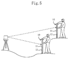
In the above embodiment, the light receiving point
sensing device is applied to the light beam sensor 100. However,
a light receiving point sensing device of the present
invention may be applied to electronic level rods 10, 10 as
shown in Fig. 5. In this case, a device body 11 is formed to
have a sufficiently large length (about 1m to 2m, for example)
and a light-receiving part 12 is also formed to have a
sufficiently large length. The light-receiving part 12 may
be composed of a large number of pairs of solar cell panels
dependent on an accuracy of detection. Through the use of such
electronic level rods 10, 10, projections, depressions and
tilts of the ground can be measured with ease.
Claims (7)
- A light receiving point sensing device having: light-receiving means which is placed on an object to be measured in the form of extending along a direction of locating the object and receives a reference light beam; and detecting means for detecting a deviation in the direction of locating the object of an actual light receiving point with respect to a reference light receiving point preset in the light-receiving means, whereinthe light-receiving means comprises a pair of photoelectric conversion panels composed of: a first photoelectric conversion panel having the form that an area of its light-receptive surface gradually increases from one side of the direction of locating the object toward the other side thereof; and a second photoelectric conversion panel which is placed at a position adjacent to the first photoelectric conversion panel in a direction orthogonal to the direction of locating the object and has the form that an area of its light-receptive surface gradually decreases from one side of the direction of locating the object toward the other side thereof and, andthe detecting means is adapted to detect a deviation of the actual light receiving point with respect to the reference light receiving point based on a signal outputted from the first photoelectric conversion panel and a signal outputted from the second photoelectric conversion panel.
- A light receiving point sensing device according to claim 1, wherein the light-receiving means comprises at least two pairs of photoelectric conversion panels, said pairs are aligned along the direction of locating the object to be measured.
- A light receiving point sensing device according to claim 1, wherein the pair of photoelectric conversion panels are each formed in a right-angled triangle and are placed to be adjacent at hypotenuses to each other.
- A light receiving point sensing device according to claim 1, wherein the outline of the light-receptive surface of the photoelectric conversion panel is formed through masking with the use of light-tight material.
- A light receiving point sensing device according to claim 1, wherein the detecting means is configured to detect a deviation of the actual light receiving point with respect to the reference light receiving point based on a subtraction between a signal outputted from the first photoelectric conversion panel and a signal outputted from the second photoelectric conversion panel.
- A light receiving point sensing device according to claim 1, further comprising:a reference point indicating line provided with respect to the reference light receiving point;a scale calibrated from the reference light receiving point toward both sides in the direction of locating an object to be measured; andindicating means for numerically indicating a deviation detected by the detecting means.
- A light receiving point sensing device according to claim 1, further comprising communicating means for transmitting a deviation detected by the detecting means to external equipment.
Applications Claiming Priority (2)
| Application Number | Priority Date | Filing Date | Title |
|---|---|---|---|
| JP209984/96 | 1996-08-08 | ||
| JP8209984A JP2859218B2 (en) | 1996-08-08 | 1996-08-08 | Light receiving position detector |
Publications (2)
| Publication Number | Publication Date |
|---|---|
| EP0823615A2 true EP0823615A2 (en) | 1998-02-11 |
| EP0823615A3 EP0823615A3 (en) | 1999-03-31 |
Family
ID=16581941
Family Applications (1)
| Application Number | Title | Priority Date | Filing Date |
|---|---|---|---|
| EP97113154A Withdrawn EP0823615A3 (en) | 1996-08-08 | 1997-07-30 | Light receiving point sensing device |
Country Status (2)
| Country | Link |
|---|---|
| EP (1) | EP0823615A3 (en) |
| JP (1) | JP2859218B2 (en) |
Cited By (3)
| Publication number | Priority date | Publication date | Assignee | Title |
|---|---|---|---|---|
| EP1039263A2 (en) * | 1999-03-26 | 2000-09-27 | Kabushiki Kaisha Topcon | Surveying system |
| WO2013024102A1 (en) * | 2011-08-16 | 2013-02-21 | Leica Geosystems Ag | Multi psd-arrangement and circuitry |
| CN108663034A (en) * | 2018-08-09 | 2018-10-16 | 常州米德克光电科技有限公司 | A kind of laser pickoff |
Families Citing this family (1)
| Publication number | Priority date | Publication date | Assignee | Title |
|---|---|---|---|---|
| JP2007298487A (en) * | 2006-05-08 | 2007-11-15 | Nippo Corporation:Kk | Laser photodetector, and height measuring method by laser photodetector |
Citations (5)
| Publication number | Priority date | Publication date | Assignee | Title |
|---|---|---|---|---|
| US4030832A (en) * | 1975-02-10 | 1977-06-21 | Spectra-Physics, Inc. | Automatic grade rod and method of operation |
| US4676634A (en) * | 1985-08-05 | 1987-06-30 | Spectra-Physics, Inc. | Detector device for a rotating light beam |
| EP0262764A1 (en) * | 1986-09-30 | 1988-04-06 | Spectra-Physics, Inc. | Elevation indication system for a large earthworking implement |
| EP0353968A1 (en) * | 1988-08-05 | 1990-02-07 | Spectra Precision, Inc. | Detection and display device |
| EP0426287A1 (en) * | 1989-10-30 | 1991-05-08 | Spectra Precision, Inc. | Improved detection and display device |
-
1996
- 1996-08-08 JP JP8209984A patent/JP2859218B2/en not_active Expired - Lifetime
-
1997
- 1997-07-30 EP EP97113154A patent/EP0823615A3/en not_active Withdrawn
Patent Citations (5)
| Publication number | Priority date | Publication date | Assignee | Title |
|---|---|---|---|---|
| US4030832A (en) * | 1975-02-10 | 1977-06-21 | Spectra-Physics, Inc. | Automatic grade rod and method of operation |
| US4676634A (en) * | 1985-08-05 | 1987-06-30 | Spectra-Physics, Inc. | Detector device for a rotating light beam |
| EP0262764A1 (en) * | 1986-09-30 | 1988-04-06 | Spectra-Physics, Inc. | Elevation indication system for a large earthworking implement |
| EP0353968A1 (en) * | 1988-08-05 | 1990-02-07 | Spectra Precision, Inc. | Detection and display device |
| EP0426287A1 (en) * | 1989-10-30 | 1991-05-08 | Spectra Precision, Inc. | Improved detection and display device |
Cited By (5)
| Publication number | Priority date | Publication date | Assignee | Title |
|---|---|---|---|---|
| EP1039263A2 (en) * | 1999-03-26 | 2000-09-27 | Kabushiki Kaisha Topcon | Surveying system |
| EP1039263A3 (en) * | 1999-03-26 | 2002-04-10 | Kabushiki Kaisha Topcon | Surveying system |
| WO2013024102A1 (en) * | 2011-08-16 | 2013-02-21 | Leica Geosystems Ag | Multi psd-arrangement and circuitry |
| US9121695B2 (en) | 2011-08-16 | 2015-09-01 | Leica Geosystems Ag | Multi PSD-arrangement and circuitry |
| CN108663034A (en) * | 2018-08-09 | 2018-10-16 | 常州米德克光电科技有限公司 | A kind of laser pickoff |
Also Published As
| Publication number | Publication date |
|---|---|
| JPH1047956A (en) | 1998-02-20 |
| EP0823615A3 (en) | 1999-03-31 |
| JP2859218B2 (en) | 1999-02-17 |
Similar Documents
| Publication | Publication Date | Title |
|---|---|---|
| CN106225682B (en) | Measuring device and method for the vertical displacement of large structure ontology and ground settlement | |
| US5371951A (en) | Two-axis inclinometer | |
| CN206223097U (en) | For the vertical displacement of large structure body and the measurement apparatus of ground settlement | |
| JPH04350513A (en) | Instrument for level of laser light ray | |
| CN103147466B (en) | Automatic inclination measurement device for precast pile with rectangular or hollow rectangular cross section | |
| JPS60219528A (en) | Molten silica diaphragm module for high-temperature pressuretransducer | |
| US5235179A (en) | Evanescent wave liquid level sensor with density compensation | |
| CN103439530A (en) | Optical accelerometer | |
| US4457626A (en) | Apparatus for determining the position of a mark on an object | |
| EP0823615A2 (en) | Light receiving point sensing device | |
| US4087920A (en) | Two-fluid tiltmeter | |
| CN100561197C (en) | Utilize laser feedback to determine the method and the application thereof of incident angle | |
| CN110132160A (en) | A kind of Measurement Methods Of Bridge Deflection using optical fiber source | |
| JPH05322562A (en) | Electronic level and level rod therefor | |
| Woschitz et al. | Development of a vertical comparator for system calibration of digital levels | |
| Huggett | Two-color terrameter | |
| EP0157606B1 (en) | High temperature pressure transducers and systems for determining deflection of pressure transducer diaphragms | |
| CN113818486A (en) | Steel shell pipe joint segmented splicing precision control method | |
| CN110360988A (en) | One kind is from temperature compensation fiber grating level inclinometer and tilts calculation method | |
| JP3510215B2 (en) | Tilt angle detecting device and tilt angle measuring method in one-dimensional measuring direction | |
| EP0046647A3 (en) | Digital measuring device | |
| JPH0645848Y2 (en) | Light receiving device of a surveying device for detecting the position of a light beam forming a plane | |
| CN220270736U (en) | Large-span bridge deflection symmetrical measurement system based on laser displacement sensor | |
| CN116026310B (en) | Integrated optical gyroscope, modulation system and light source noise suppression method | |
| CN110082843A (en) | A kind of weak reflection fiber grating rainfall gauge of the siphonic of sloping float formula and rainfall gauge array |
Legal Events
| Date | Code | Title | Description |
|---|---|---|---|
| PUAI | Public reference made under article 153(3) epc to a published international application that has entered the european phase |
Free format text: ORIGINAL CODE: 0009012 |
|
| AK | Designated contracting states |
Kind code of ref document: A2 Designated state(s): CH DE GB LI |
|
| PUAL | Search report despatched |
Free format text: ORIGINAL CODE: 0009013 |
|
| AK | Designated contracting states |
Kind code of ref document: A3 Designated state(s): AT BE CH DE DK ES FI FR GB GR IE IT LI LU MC NL PT SE |
|
| AKX | Designation fees paid |
Free format text: CH DE GB LI |
|
| STAA | Information on the status of an ep patent application or granted ep patent |
Free format text: STATUS: THE APPLICATION IS DEEMED TO BE WITHDRAWN |
|
| 18D | Application deemed to be withdrawn |
Effective date: 19991001 |