EP0823579A1 - Dispositif pour le chemisage d'un branchement, procédé de chemisage et gaine de chemisage - Google Patents
Dispositif pour le chemisage d'un branchement, procédé de chemisage et gaine de chemisage Download PDFInfo
- Publication number
- EP0823579A1 EP0823579A1 EP97401905A EP97401905A EP0823579A1 EP 0823579 A1 EP0823579 A1 EP 0823579A1 EP 97401905 A EP97401905 A EP 97401905A EP 97401905 A EP97401905 A EP 97401905A EP 0823579 A1 EP0823579 A1 EP 0823579A1
- Authority
- EP
- European Patent Office
- Prior art keywords
- pipe
- sheath
- arm
- balloon
- working
- Prior art date
- Legal status (The legal status is an assumption and is not a legal conclusion. Google has not performed a legal analysis and makes no representation as to the accuracy of the status listed.)
- Withdrawn
Links
- 238000000034 method Methods 0.000 title claims description 16
- 239000012530 fluid Substances 0.000 claims abstract description 26
- 229920005989 resin Polymers 0.000 claims abstract description 21
- 239000011347 resin Substances 0.000 claims abstract description 21
- 238000006073 displacement reaction Methods 0.000 claims description 6
- 238000010438 heat treatment Methods 0.000 claims description 6
- 229920001187 thermosetting polymer Polymers 0.000 claims description 5
- 239000000463 material Substances 0.000 description 6
- 238000006116 polymerization reaction Methods 0.000 description 5
- 230000000694 effects Effects 0.000 description 3
- 238000009434 installation Methods 0.000 description 3
- 239000011324 bead Substances 0.000 description 2
- 239000002131 composite material Substances 0.000 description 2
- 230000000379 polymerizing effect Effects 0.000 description 2
- 238000005096 rolling process Methods 0.000 description 2
- 230000007704 transition Effects 0.000 description 2
- 235000001674 Agaricus brunnescens Nutrition 0.000 description 1
- 239000004698 Polyethylene Substances 0.000 description 1
- 235000014443 Pyrus communis Nutrition 0.000 description 1
- 230000005465 channeling Effects 0.000 description 1
- 238000005553 drilling Methods 0.000 description 1
- 239000003822 epoxy resin Substances 0.000 description 1
- 239000000835 fiber Substances 0.000 description 1
- 239000011152 fibreglass Substances 0.000 description 1
- 239000004746 geotextile Substances 0.000 description 1
- 238000005470 impregnation Methods 0.000 description 1
- 239000012528 membrane Substances 0.000 description 1
- 239000004745 nonwoven fabric Substances 0.000 description 1
- 230000035515 penetration Effects 0.000 description 1
- ISWSIDIOOBJBQZ-UHFFFAOYSA-N phenol group Chemical group C1(=CC=CC=C1)O ISWSIDIOOBJBQZ-UHFFFAOYSA-N 0.000 description 1
- 239000004033 plastic Substances 0.000 description 1
- 229920003023 plastic Polymers 0.000 description 1
- 229920000647 polyepoxide Polymers 0.000 description 1
- 229920000728 polyester Polymers 0.000 description 1
- -1 polyethylene Polymers 0.000 description 1
- 229920000573 polyethylene Polymers 0.000 description 1
- 229920002635 polyurethane Polymers 0.000 description 1
- 239000004814 polyurethane Substances 0.000 description 1
- 229920000915 polyvinyl chloride Polymers 0.000 description 1
- 239000004800 polyvinyl chloride Substances 0.000 description 1
- 238000009958 sewing Methods 0.000 description 1
- 229920002994 synthetic fiber Polymers 0.000 description 1
- 229920001567 vinyl ester resin Polymers 0.000 description 1
- XLYOFNOQVPJJNP-UHFFFAOYSA-N water Substances O XLYOFNOQVPJJNP-UHFFFAOYSA-N 0.000 description 1
- 238000004078 waterproofing Methods 0.000 description 1
Images

Classifications
-
- F—MECHANICAL ENGINEERING; LIGHTING; HEATING; WEAPONS; BLASTING
- F16—ENGINEERING ELEMENTS AND UNITS; GENERAL MEASURES FOR PRODUCING AND MAINTAINING EFFECTIVE FUNCTIONING OF MACHINES OR INSTALLATIONS; THERMAL INSULATION IN GENERAL
- F16L—PIPES; JOINTS OR FITTINGS FOR PIPES; SUPPORTS FOR PIPES, CABLES OR PROTECTIVE TUBING; MEANS FOR THERMAL INSULATION IN GENERAL
- F16L55/00—Devices or appurtenances for use in, or in connection with, pipes or pipe systems
- F16L55/16—Devices for covering leaks in pipes or hoses, e.g. hose-menders
- F16L55/179—Devices for covering leaks in pipes or hoses, e.g. hose-menders specially adapted for bends, branch units, branching pipes or the like
-
- F—MECHANICAL ENGINEERING; LIGHTING; HEATING; WEAPONS; BLASTING
- F16—ENGINEERING ELEMENTS AND UNITS; GENERAL MEASURES FOR PRODUCING AND MAINTAINING EFFECTIVE FUNCTIONING OF MACHINES OR INSTALLATIONS; THERMAL INSULATION IN GENERAL
- F16L—PIPES; JOINTS OR FITTINGS FOR PIPES; SUPPORTS FOR PIPES, CABLES OR PROTECTIVE TUBING; MEANS FOR THERMAL INSULATION IN GENERAL
- F16L55/00—Devices or appurtenances for use in, or in connection with, pipes or pipe systems
- F16L55/26—Pigs or moles, i.e. devices movable in a pipe or conduit with or without self-contained propulsion means
- F16L55/265—Pigs or moles, i.e. devices movable in a pipe or conduit with or without self-contained propulsion means specially adapted for work at or near a junction between a main and a lateral pipe
-
- B—PERFORMING OPERATIONS; TRANSPORTING
- B29—WORKING OF PLASTICS; WORKING OF SUBSTANCES IN A PLASTIC STATE IN GENERAL
- B29C—SHAPING OR JOINING OF PLASTICS; SHAPING OF MATERIAL IN A PLASTIC STATE, NOT OTHERWISE PROVIDED FOR; AFTER-TREATMENT OF THE SHAPED PRODUCTS, e.g. REPAIRING
- B29C63/00—Lining or sheathing, i.e. applying preformed layers or sheathings of plastics; Apparatus therefor
- B29C63/26—Lining or sheathing of internal surfaces
- B29C63/28—Lining or sheathing of internal surfaces applied by "rubber" bag or diaphragm
Definitions
- the present invention relates to a device for setting up a liner sheath with a connection between a first and a second pipeline.
- the sheath is in the form of a cylindrical element which is located in a current portion of the pipeline.
- the present invention aims to provide a device for setting place a liner sheath at a connection between a first and a second pipe, that is to say more particularly in the area intersection between the pipes.
- Document DE 44 00 742 shows a device which includes a trolley provided with displacement members (constituted by wheels) and means for controlling the movement of the carriage, the latter having a support plate for a tool located in the vicinity of one of its ends, the tool being provided with a balloon capable of being inflated by means of a inflation fluid for applying the sheath at least in a neighboring area of the intersection of said pipes, the device comprising means of inflation and deflation of the balloon.
- the installation of the sheath is carried out by making pivot the support plate relative to the carriage body which is located in the second pipeline. This movement does not allow to master with precision the introduction of the sheath into the first pipe. It is furthermore difficult to make the longitudinal axis of the first part coincide of the sheath with the axis of the first pipe.
- the present invention proposes to remedy these drawbacks.
- the tool comprises a telescopic arm capable of pivot relative to the plate, about an axis substantially perpendicular to the latter, this arm having an end portion called “of work ", capable of being moved in translation, the balloon equipping this working end being able to apply a first and a second part of the sheath respectively against the wall of the first pipe and against that of the second pipe.
- the device comprises, in in addition, means for controlling the pivoting of the telescopic arm and means for controlling the movement of the working part of this arm.
- the carriage can be moved in the second pipeline (for example a pipeline main) until it comes substantially to the right of the first pipeline (for example a bypass line).
- the sheath may have been placed on the balloon in the deflated state and be directly transported until connected by the trolley.
- the sheath When the installation of the sheath is complete, it presents a first part which extends into the first pipe, as well as a second part which extends into the second pipe. Good obviously the area of intersection between the pipes is then covered by the intermediate zone of the sheath between its first and its second part. The connection is thus completely rehabilitated, the sheath being present in all fragile areas.
- the hardening of the sheath (the polymerization of the resin which impregnation) can be obtained using a polymerization device separate, such as a heating system or an ultraviolet ray system.
- a polymerization device separate, such as a heating system or an ultraviolet ray system.
- the invention advantageously provides that the inflation fluid of the balloon is a hot fluid, in which case we realize at the same time the application of the sheath against the walls of the branch and the polymerization of the resin.
- the current areas of the pipes can be rehabilitated in a classic way.
- the invention also relates to a method for setting up a liner sheath with a connection between a first and a second pipeline.
- the object of the invention is therefore, for a process in which a carriage having, near one of its ends, a plate of support for a tool provided with a balloon capable of being inflated by means of a inflation fluid and to wear the liner sheath, to propose a process which allows to put in place a jacket sheath in the area of the connection between two pipes and, specifically, to protect the intersection between these two pipes.
- the method according to the invention allows, so very simple, bring the liner sheath to the desired position and then implement.
- the sheath can be previously arranged on the balloon in the uninflated state and the arm placed in a position in which it does not exceed the volume enveloping the carriage so as to prevent it from hangs on the wall of the pipe when the carriage moves.
- the method may include a step of polymerizing the resin which can be achieved by using a heated fluid to inflate the balloon.
- the invention also relates to a sheath for the lining of a connection between a first and a second pipe.
- sheaths which are given a cylindrical shape to line a portion current of a pipeline.
- the invention therefore aims to provide a sheath which allows to line such a connection, especially in this transition zone.
- the sheath according to the invention comprises a first part intended to be applied against the wall of the first pipe for line an end part of this first pipe close to its intersection with the second pipe, and a second part, connected to said first part and intended to be applied against the wall of the second pipe at least in an area close to said intersection.
- sheath according to the invention forms an assembly continuous including the intermediate zone between the first and second parts line the intersection area between the two pipes.
- the second part can be constituted by a flange extending substantially radially with respect to the first part which is cylindrical.
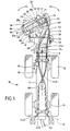
- the device of FIG. 1 comprises a carriage, designated by the general reference 10, provided with displacement members, constituted in the example represented by wheels 12.
- the shape and dimension of this device allow it to move inside a pipeline.
- the device comprises means for controlling the movement of the cart.
- these means include an electric motor 14 able to rotate one of the pairs of wheels, this motor being powered by an electric cable 16 which is brought to one end of the pipeline or on the surface, i.e. where there may be a manipulator.
- an electric motor 14 able to rotate one of the pairs of wheels, this motor being powered by an electric cable 16 which is brought to one end of the pipeline or on the surface, i.e. where there may be a manipulator.
- any type of engine control can be used, for example a wired or wireless remote control.
- the carriage 10 has a support plate 18 for a tool. This plate is located in the vicinity of one of the longitudinal ends of the carriage which will be referred to hereinafter as "head" of the carriage.
- the head of the carriage is shown in more detail clearly. describe the operation of the tool. However, this representation remains schematic, so some of the elements that are actually hidden in a exterior view, are shown in solid lines to clearly show their position.
- the tool comprises a telescopic arm 20 capable of pivoting by relative to the plate 18 around an axis 22 substantially perpendicular to this turntable. More specifically, the telescopic arm is mounted on an arm of support 24 which is arranged on the plate 18. It is this support arm which pivots relative to the plate about the axis 22. The telescopic arm is meanwhile mounted on this support arm 24.
- the arm 24 has the form an L, the base of which is mounted on the plate 18 and the raised part of which receives one end of the arm 20.
- This telescopic arm has an end portion 26 called “end of work ". It is this end that is likely to be moved in translation when stretching or retracting the telescopic arm. She is provided with a balloon 28 shown in broken dashed lines. This balloon 28 can be inflated using an inflation fluid to apply the sheath against the walls of the pipes, at least in the area of their intersection.
- the device comprises means for controlling the pivoting of the telescopic arm 20, means for controlling the movement of the part of work 26 of this arm and of the means for controlling the inflation and the deflating the balloon.
- a simple embodiment of the control means of the pivoting of the telescopic arm associates a traction cable and a spring reminder.
- the cable 30 is, on the one hand, connected to the telescopic arm or, in the example shown, on the support arm 24, in an area 32 offset by relative to the axis of rotation 22 and, on the other hand, connected to means of rearward traction, constituted in the example represented by a motor 34 which can be operated remotely using an electric cable 36.
- a motor 34 which can be operated remotely using an electric cable 36.
- a return spring 38 is connected, on the one hand, to the support arm 24 in an eccentric zone 40 located the other side of axis 22 with respect to zone 32 and, on the other hand, to an element fixed such as plate 18.
- the telescopic arm 20 advantageously comprises a jack comprising a rod 21 and a cylinder 23. Its working end 26 is then constituted by at least one portion of cylinder 23, around which the balloon 28 is arranged. In the example represented, the working part 26 is practically constituted by the entirety of the cylinder 23.
- the rod 21 of the jack remains fixed in translation and this is the cylinder which is moved when stretching or retracting the arm telescopic.
- the means of controlling the movement of this working part include fluid circulation conduits, two conduits 42 and 44 which both open into the chamber 46 formed between the rod 21 and the cylinder 23.
- the duct 42 comprises a drilling section 43 produced in the rod 21 and opens in the vicinity of the free end 21a of the latter, while the conduit 44 opens into the chamber 46 in the vicinity of the cylinder wall 23.
- These conduits 42 and 44 are connected to pipes, respectively 42A and 44A which are themselves brought towards the end rear of the device to be connected to a fluid circuit.
- the device may include another cylinder endowing the head with a capacity to move along arrow F2, transversely to the carriage.
- This cylinder is designated by the general reference 48 in Figure 1. It can be supplied with fluid independently of the telescopic arm 20.
- conduits 50 and 52 for fluid circulation which enable actuator 48 can be connected in parallel to conduits 42 and 44 using branches on conduits 42A and 44A.
- the head of the device can itself be provided with a capacity of displacement relative to the rest of the body 11 of the carriage. To this end, it may contain one or more cylinders which are supplied with fluid at stiff pipes which, in Figure 1 are generally included in a socket connection 54.
- the front end 11a of the body of the carriage, on which are successively mounted the cylinder 48 and the plate 18 can be the end of a cylinder rod capable of moving according to arrow F1 parallel to the longitudinal axis A of the carriage body. Means can also be used to control the rotation of this end 11a around the axis A.
- the carriage head can be equipped with a camera.
- a second carriage placed in front of the first and carrying a camera pointing on the connection.
- the balloon 28 is inflated using fluid circulation pipes which both lead into chamber 56 formed between the balloon and the outer wall of the cylinder 23.
- the first pipe 58 is connected to a bore in the rear ring 60 which holds the end back of the ball (its end opposite the free end of the arm telescopic) relative to the cylinder 23.
- the second pipe 62 can as for it lead to the vicinity of the front end of the chamber 56.
- it is connected to a bore 63 of the rod 21, the bore itself connected to a hose 64 long enough to accompany extension and retraction of the telescopic arm 26, this flexible being connected to a hole in the wall of the cylinder 23 and thus opening out near the front end of the balloon.
- the various fluid circulation pipes used to supply the cylinders, or to inflate or deflate the balloon, can be connected to fluid circuits in which circulation is managed at the surface by a manipulator.
- Parts such as necklaces 66 or mushroom stem 68 may be provided to keep the various conduits as close as possible to the body 11 of the carriage.
- the balloon 28 is held on the working end 26 of the arm 20 by a ring 66 located at its front end 28a and a ring 60, previously mentioned, located at its rear end 28b.
- this balloon when practically deflated, presents overall the shape of a pear, the diameter of its rear end 28b being greater than that of its front end 28a. Thanks to these provisions it presents, in the inflated state, a swollen zone which is towards its end back. We will see below that this bulged area is used to properly apply the collar of the sheath against the edge of the intersection of the secondary pipe and main pipeline.
- the device advantageously includes means for heating the balloon inflation fluid.
- the inflation of the balloon serves not only to apply the sheath against the walls of the pipes, but also to harden the resin with which it is coated.
- These heating means may for example consist of a resistor (not shown) located on the path of the fluid circulating in the conduits 58 and 62.
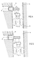
- the balloon and the sheath it carries have penetrated a length sufficient in line 72, the balloon is inflated to bring it into the situation illustrated by FIG. 5 so as to respectively apply the first and second part of the sheath, respectively 71a and 71b, against the walls of the first and second pipes.
- the balloon 28 is inflated so as to conform to the shape of the line 72 for all of its front part 28a, which enables the first part 71a of the sheath against the wall of the pipe 72.
- a the rear of the balloon formed the bead 28b whose diameter is greater to that of the first pipe and this bead presses the second part 71b of the sheath, which we will see later that it can adopt the shape of a collar, to apply it on the wall of the second line 74, around the intersection between lines 72 and 74.
- the sheath 70 has, from before its establishment, a first part 71a which is generally cylindrical and a second part 71b which is raised radially and forms a collar located at the end of the sheath intended to be in the second line 74.
- the effect of balloon inflation is to apply the first part 71a of the sheath against the wall of the first pipe 72 and apply the second part of the sheath, i.e. the flange against the wall of the second pipe 74.
- the first part 71a has the shape of a tubular sleeve, while the second part 71b has the shape of a washer arranged transversely, at one end of the sleeve, to form a collar.
- the two parts are connected to using an intermediate strip 71c glued and / or sewn which, in the example shown, is on the inner face of the sheath.
- the first part 71a made from a plate of material rolled on itself in the manner of a cylinder, has a longitudinal zone 71d of seam and / or bonding of the two ends of this plate.
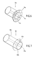
- the sheath may initially have the form of a tube and be brought to the desired shape for the lining under the effect of inflation of the ball.
- FIG. 7 shows a sheath of this type, designated by the reference 80.
- This sheath is produced for example by rolling a plate of material so as to join its two opposite ends on an area 80a of sewing and / or collage.
- a ends 80b of this sheath can fold radially outwards so as to form a collar 81b shown in phantom interrupted.
- This flange 81b therefore forms the second part of the sheath which is applied against the wall of the second pipe, while the rest of the sheath forms the first part 81a which is applied against the wall of the first pipe.
- this sheath 80 To set up this sheath 80, the part of work 26 of the telescopic arm 20 in the first pipe 72 while further up to a position in which only front portions of the sheath and of the balloon are arranged in this first pipe.
- the end 80b of the sheath is left outside this pipe from which we will deform the flange 81a and the rear part of the balloon which, when the latter is inflated, will form the bulge 28b.
- These rear parts 80b of the sheath and 28b of the balloon therefore protrude outside of the first pipe 72, inside the second pipe 74.
- the balloon can initially exhibit a natural tendency to have a larger diameter towards its rear part than towards its front part, to naturally form the bulge 28b.
- the inflation of the balloon can bring its front part to the maximum of the diameter of this first pipe, while its rear part, if the inflation pressure is increased, will naturally tend to have a bulge of diameter greater than that of the first pipe.
- the sheath (70 or 80) is coated with a resin thermosetting
- a fluid e.g. water
- this hot fluid e.g. water
- It is made of a material, for example plastic, which lets the heat.
- the sheath for the connection lining has a first part (71a or 81a) intended to be applied against the wall of the first pipe 72 for line an end part of this first pipe close to its intersection with the second line 74, and a second part (71b or 81b) connected to the first part and intended, for its part, to be applied against the wall of the second pipe 74 at least in one area close to the intersection between the two pipes.
- This zone neighbor extends around the entire perimeter of the intersection, so that the second part of the sheath can, as indicated previously, present the shape of a collar.
- the sheath can have a laminated structure. More specifically, it may include a first sleeve made of a composite material permeable to polymerizable resin.
- this composite material can be a fiberglass nonwoven fabric laminate or any material of the same type.
- This first sleeve can be produced by cutting strips of material and rolling them on themselves to join their opposite ends. Alternatively, a woven or a nonwoven having the shape of a sleeve.
- the sheath may include a second sleeve which will form its inner membrane and can be made of any waterproof synthetic material such as PVC, polyethylene, or polyurethane or any other material of the same type.
- this second sleeve On its internal face, intended to come into contact with the first sleeve, this second sleeve may include a geotextile of fibers that can adhere to the first sleeve when it is coated with resin.
- the sheath may also include a third sleeve which will come constitute its external face. This third sleeve is analogous to the second and is arranged so that the first sleeve is sandwiched between the other two.
- the thermosetting resin is for example a epoxy resin, polyester, vinylester or phenolic.
- the first sleeve coated with this resin will restore to the pipe jacketed the desired mechanical strength. In terms of waterproofing, rather, this can be ensured thanks to the presence of the second and / or the third sleeve.
- the lining is guaranteed without any discontinuity in the intersection area of the first and second pipes.
- connection sleeve sheath is located at the end of the secondary pipe close to its intersection with the main line and passes through the opening of the liner 82. Its collar is folded over the edge of this opening.
Landscapes
- Engineering & Computer Science (AREA)
- General Engineering & Computer Science (AREA)
- Mechanical Engineering (AREA)
- Chemical & Material Sciences (AREA)
- Combustion & Propulsion (AREA)
- Pipe Accessories (AREA)
- Lining Or Joining Of Plastics Or The Like (AREA)
Abstract
Description
- on dispose la gaine de chemisage sur le ballon, autour de la partie de travail du bras télescopique, en plaçant la partie de la gaine destinée à s'étendre dans la première canalisation du côté de l'extrémité libre de ladite partie de travail,
- tout en maintenant le bras dans une position rétractée, on déplace le chariot à l'intérieur de la deuxième canalisation jusqu'à amener le bras sensiblement au niveau de la première canalisation,
- on fait pivoter le bras de manière à sensiblement l'aligner avec l'axe de la première canalisation,
- on déplace la partie de travail du bras pour la faire pénétrer dans ladite première canalisation et on gonfle le ballon pour appliquer respectivement les première et deuxième parties de la gaine contre les parois des première et deuxième canalisations.
- la figure 1 est une vue schématique de dessus montrant un dispositif conforme à l'invention,
- les figures 2 à 5 sont des vues schématiques montrant des étapes successives du procédé conforme à l'invention, et,
- les figures 6 et 7 montrent deux variantes d'une gaine conforme à l'invention.
Claims (10)
- Dispositif pour mettre en place une gaine de chemisage à un branchement entre une première et une deuxième canalisation, comportant un chariot (10) muni d'organes de déplacement (12) et des moyens (14, 16) de commande du déplacement du chariot, ce dernier présentant une platine de support (18) pour un outil située au voisinage de l'une de ses extrémités, l'outil étant muni d'un ballon (28) apte à être gonflé au moyen d'un fluide de gonflage pour appliquer la gaine au moins dans une zone voisine de l'intersection desdites canalisations, le dispositif comprenant des moyens (58, 62) de commande du gonflage et du dégonflage du ballon,
caractérisé en ce que l'outil comporte un bras télescopique (20) susceptible de pivoter par rapport à la platine (18), autour d'un axe (22) sensiblement perpendiculaire à cette dernière, ce bras ayant une partie d'extrémité (26) dite "de travail", susceptible d'être déplacée en translation, le ballon équipant ladite extrémité de travail et étant apte à appliquer une première et une deuxième partie de la gaine respectivement contre la paroi de la première canalisation (72) et contre celle de la deuxième canalisation (74) et en ce que le dispositif comprend en outre des moyens (30, 34, 38) de commande du pivotement du bras télescopique (20) et des moyens (42, 44) de commande du déplacement de la partie de travail (26) de ce bras (20). - Dispositif selon la revendication 1, caractérisé en ce que le bras télescopique (20) comporte un vérin comprenant une tige (21) et un cylindre (23), la partie de travail (26) du bras étant constituée par au moins une portion du cylindre (23) autour de laquelle est disposé le ballon (28), la tige restant fixe en translation au cours du déplacement de ladite partie de travail.
- Dispositif selon la revendication 2, caractérisé en ce qu'il comporte un bras de support (24), disposé sur la platine (18) et apte à pivoter par rapport à cette dernière et en ce que la tige (21) du vérin est fixée à ce bras de support (24).
- Dispositif selon l'une quelconque des revendications 1 à 3, caractérisé en ce que le ballon présente, à l'état gonflé, une zone renflée (28b) située à l'opposé de l'extrémité libre de la partie de travail (26) du bras télescopique (20).
- Dispositif selon l'une quelconque des revendications 1 à 4, caractérisé en ce que, la gaine étant enduite de résine thermodurcissable, le dispositif comporte des moyens de chauffage du fluide de gonflage du ballon.
- Procédé pour mettre en place une gaine de chemisage à un branchement entre une première et une deuxième canalisation, dans lequel :caractérisé en ce que, l'outil comportant un bras télescopique (20) apte à pivoter par rapport à la platine (18), autour d'un axe (22) sensiblement perpendiculaire à cette dernière, ce bras ayant une partie d'extrémité (26) dite "de travail" susceptible d'être déplacée en translation et le ballon équipant ladite extrémité de travail,on fournit un chariot (10) ayant, au voisinage de l'une de ses extrémités, une platine de support (18) pour un outil muni d'un ballon (28) apte à être gonflé au moyen d'un fluide de gonflage et à porter la gaine de chemisage,on dispose la gaine de chemisage (70 ; 80) sur le ballon (28), autour de la partie de travail (26) du bras télescopique (20), en plaçant la partie de la gaine destinée à s'étendre dans la première canalisation du côté de l'extrémité libre (26a) de ladite partie de travail,tout en maintenant le bras (20) dans une position rétractée, on déplace le chariot (10) à l'intérieur de la deuxième canalisation (74) jusqu'à amener le bras sensiblement au niveau de la première canalisation (72),on fait pivoter le bras (20) de manière à sensiblement l'aligner avec l'axe (B') de la première canalisation (72),on déplace la partie de travail (26) du bras (20) pour la faire pénétrer dans ladite première canalisation (72) et on gonfle le ballon (28) pour appliquer respectivement les première et deuxième parties (71a, 71b ; 81a, 81b) de la gaine (70 ; 80) contre les parois des première et deuxième canalisations (72, 74).
- Procédé selon la revendication 6, caractérisé en ce que, la gaine (80) ayant initialement la forme d'un tube, on fait pénétrer la partie de travail (26) du bras télescopique (20) dans la première canalisation (72) tout au plus jusqu'à une position dans laquelle seules des parties avant de la gaine et du ballon sont disposées dans cette première canalisation, des parties arrière (80b) de ladite gaine et (28b) dudit ballon dépassant, en-dehors de la première canalisation (72), à l'intérieur de la deuxième canalisation (74), et l'on gonfle le ballon (28) de manière à doter sa partie avant (28a) d'un diamètre sensiblement égal à celui de la première canalisation (72) pour appliquer la partie avant la gaine (81a) contre la paroi de cette canalisation et à doter la partie arrière de ce ballon d'un renflement (28b) de diamètre supérieur à celui de la première canalisation pour déformer la partie arrière (80b) de la gaine en lui donnant sensiblement la forme d'une collerette (81b) et l'appliquer contre la paroi de la deuxième canalisation (74).
- Procédé selon la revendication 6 ou 7, caractérisé en ce que, la gaine (70, 80) étant enduite d'une résine thermodurcissable, on chauffe un fluide pour le porter à une température de durcissement de cette résine et on utilise ce fluide chaud pour gonfler le ballon (28).
- Gaine (70, 80) pour le chemisage d'un branchement entre une première (72) et une deuxième (74) canalisation,
caractérisée en ce qu'elle comporte une première partie (71a, 81a) destinée à être appliquée contre la paroi de la première canalisation (72) pour chemiser une partie d'extrémité de cette première canalisation proche de son intersection avec la deuxième canalisation (74), et une deuxième partie (71b, 81b), raccordée à ladite première partie et destinée à être appliquée contre la paroi de la deuxième canalisation (74) au moins dans une zone voisine de ladite intersection. - Gaine selon la revendication 9, caractérisée en ce que la première partie (71a) a la forme d'un manchon tubulaire, tandis que la deuxième partie (71b) a la forme d'une collerette s'étendant, à partir de l'une des extrémités de ce manchon, sensiblement transversalement à ce dernier.
Applications Claiming Priority (2)
| Application Number | Priority Date | Filing Date | Title |
|---|---|---|---|
| FR9610041A FR2752286B1 (fr) | 1996-08-09 | 1996-08-09 | Dispositif pour le chemisage d'un branchement, procede de chemisage et gaine de chemisage |
| FR9610041 | 1996-08-09 |
Publications (1)
| Publication Number | Publication Date |
|---|---|
| EP0823579A1 true EP0823579A1 (fr) | 1998-02-11 |
Family
ID=9494943
Family Applications (1)
| Application Number | Title | Priority Date | Filing Date |
|---|---|---|---|
| EP97401905A Withdrawn EP0823579A1 (fr) | 1996-08-09 | 1997-08-08 | Dispositif pour le chemisage d'un branchement, procédé de chemisage et gaine de chemisage |
Country Status (2)
| Country | Link |
|---|---|
| EP (1) | EP0823579A1 (fr) |
| FR (1) | FR2752286B1 (fr) |
Cited By (7)
| Publication number | Priority date | Publication date | Assignee | Title |
|---|---|---|---|---|
| EP1519100A1 (fr) * | 2003-09-25 | 2005-03-30 | Epros GmbH | Appareil et méthode pour la renovation de canalisations |
| KR100497117B1 (ko) * | 2002-10-24 | 2005-06-28 | 김일환 | 지관보수 자주차를 이용한 지관보수 장치 및 방법 |
| KR101157080B1 (ko) | 2011-12-26 | 2012-06-21 | (주)알파에코 | 하수관과 가지관 접합부의 비굴착 보수 장치 및 보수 방법 |
| WO2016062664A1 (fr) * | 2014-10-19 | 2016-04-28 | National Grid Gas Plc | Appareil et procédé |
| WO2016192817A1 (fr) * | 2015-05-29 | 2016-12-08 | National Grid Gas Plc | Appareil et procédé de revêtement de tuyau latéral |
| CN111853423A (zh) * | 2020-07-21 | 2020-10-30 | 武汉巴弗智能科技有限公司 | 一种管道支管检测系统 |
| CN116906721A (zh) * | 2023-06-26 | 2023-10-20 | 长江生态环保集团有限公司 | 一种适用深埋管道的封堵系统及封堵方法 |
Citations (5)
| Publication number | Priority date | Publication date | Assignee | Title |
|---|---|---|---|---|
| WO1990005874A1 (fr) * | 1988-11-21 | 1990-05-31 | Kunststoff-Technik Aktiengesellschaft Himmler | Procede pour reparer une canalisation domestique inaccessible au moyen d'un dispositif telecommande operant dans la conduite principale |
| DE4400742A1 (de) * | 1994-01-13 | 1995-07-20 | Jt Elektronik Gmbh | Vorrichtung zur Sanierung von Hausanschlüssen |
| EP0674132A1 (fr) * | 1994-03-21 | 1995-09-27 | Pmo Engineering Ag | Dispositif et procédé pour étancher la zone de jonction d'un tuyau de dérivation dans un tuyau principal |
| WO1996012134A1 (fr) * | 1994-10-14 | 1996-04-25 | Uffmann Hans Peter | Procede et dispositif de renovation de tuyaux d'egouts |
| DE19507250A1 (de) * | 1995-03-02 | 1996-09-05 | Wolfgang Rausch Gmbh & Co Kg | Verfahren zur Dichtigkeitsprüfung der Verbindung zwischen einer Rohrleitung und einer an sie angeschlossenen Abzweigleitung sowie Vorrichtung zur Durchführung des Verfahrens |
-
1996
- 1996-08-09 FR FR9610041A patent/FR2752286B1/fr not_active Expired - Fee Related
-
1997
- 1997-08-08 EP EP97401905A patent/EP0823579A1/fr not_active Withdrawn
Patent Citations (5)
| Publication number | Priority date | Publication date | Assignee | Title |
|---|---|---|---|---|
| WO1990005874A1 (fr) * | 1988-11-21 | 1990-05-31 | Kunststoff-Technik Aktiengesellschaft Himmler | Procede pour reparer une canalisation domestique inaccessible au moyen d'un dispositif telecommande operant dans la conduite principale |
| DE4400742A1 (de) * | 1994-01-13 | 1995-07-20 | Jt Elektronik Gmbh | Vorrichtung zur Sanierung von Hausanschlüssen |
| EP0674132A1 (fr) * | 1994-03-21 | 1995-09-27 | Pmo Engineering Ag | Dispositif et procédé pour étancher la zone de jonction d'un tuyau de dérivation dans un tuyau principal |
| WO1996012134A1 (fr) * | 1994-10-14 | 1996-04-25 | Uffmann Hans Peter | Procede et dispositif de renovation de tuyaux d'egouts |
| DE19507250A1 (de) * | 1995-03-02 | 1996-09-05 | Wolfgang Rausch Gmbh & Co Kg | Verfahren zur Dichtigkeitsprüfung der Verbindung zwischen einer Rohrleitung und einer an sie angeschlossenen Abzweigleitung sowie Vorrichtung zur Durchführung des Verfahrens |
Cited By (11)
| Publication number | Priority date | Publication date | Assignee | Title |
|---|---|---|---|---|
| KR100497117B1 (ko) * | 2002-10-24 | 2005-06-28 | 김일환 | 지관보수 자주차를 이용한 지관보수 장치 및 방법 |
| EP1519100A1 (fr) * | 2003-09-25 | 2005-03-30 | Epros GmbH | Appareil et méthode pour la renovation de canalisations |
| US7631665B2 (en) | 2003-09-25 | 2009-12-15 | Trelleborg Pipe Seals Duisburg Gmbh | Device and method for pipeline rehabilitation |
| KR101157080B1 (ko) | 2011-12-26 | 2012-06-21 | (주)알파에코 | 하수관과 가지관 접합부의 비굴착 보수 장치 및 보수 방법 |
| WO2016062664A1 (fr) * | 2014-10-19 | 2016-04-28 | National Grid Gas Plc | Appareil et procédé |
| US10605399B2 (en) | 2014-10-19 | 2020-03-31 | Synthotech Limited | Apparatus and method for installing a connection fitting into a main pipeline |
| WO2016192817A1 (fr) * | 2015-05-29 | 2016-12-08 | National Grid Gas Plc | Appareil et procédé de revêtement de tuyau latéral |
| GB2555342A (en) * | 2015-05-29 | 2018-04-25 | Synthotech Ltd | Apparatus and method for lining a lateral pipe |
| GB2555342B (en) * | 2015-05-29 | 2021-11-10 | Synthotech Ltd | Apparatus and method for lining a lateral pipe |
| CN111853423A (zh) * | 2020-07-21 | 2020-10-30 | 武汉巴弗智能科技有限公司 | 一种管道支管检测系统 |
| CN116906721A (zh) * | 2023-06-26 | 2023-10-20 | 长江生态环保集团有限公司 | 一种适用深埋管道的封堵系统及封堵方法 |
Also Published As
| Publication number | Publication date |
|---|---|
| FR2752286A1 (fr) | 1998-02-13 |
| FR2752286B1 (fr) | 1998-10-30 |
Similar Documents
| Publication | Publication Date | Title |
|---|---|---|
| EP0115993B1 (fr) | Procédé de garnissage interne d'une conduite. | |
| EP0234142B1 (fr) | Procédé de garnissage interne de conduites | |
| CA2083156C (fr) | Preforme dispositif et procedes pour tuber et/ou chemiser un volume cylindrique | |
| CA2043579C (fr) | Reservoir pour le stockage d'un fluide sous pression et son procede de fabrication | |
| EP0536256B1 (fr) | Tube radialement deformable en plusieurs troncons raccordes de maniere demontable | |
| EP0565445B1 (fr) | Dispositif de montage d'une ligne flexible comportant un limiteur de courbure | |
| FR2717855A1 (fr) | Procédé pour rendre étanche la liaison entre un chemisage intérieur d'une part, et un puits de forage, un tubage ou une canalisation extérieure d'autre part. | |
| EP0626250B1 (fr) | Procédé de fabrication de bielle en matériau composite monobloc par mise en place de fibres pré-imprégnées sur un mandrin extractible et bielle ainsi obtenue | |
| WO1996021083A1 (fr) | Procede et dispositif pour tuber un puits, notamment un puits de forage petrolier, ou une canalisation, au moyen d'une preforme tubulaire souple, durcissable in situ | |
| EP0287429B1 (fr) | Procédé de fabrication de tubes métalliques assemblés par leurs extrémités | |
| EP0171325B1 (fr) | Dispositif de fabrication par bobinage filamentaire d'une enveloppe creuse et enveloppe obtenue à l'aide du dispositif | |
| WO1996001937A1 (fr) | Preforme, dispositif et procede pour le tubage d'un puits | |
| EP0823579A1 (fr) | Dispositif pour le chemisage d'un branchement, procédé de chemisage et gaine de chemisage | |
| EP0263760A1 (fr) | Procédé de fabrication de tubes composites pour le transport de fluides divers | |
| FR2568979A1 (fr) | Assemblage telescopique perfectionne pour reparer des canalisations sous-marines posees a de grandes profondeurs | |
| TW201237299A (en) | Lateral pipe lining method and lateral pipe lining apparatus | |
| WO2015055928A1 (fr) | Procédé de liaison d'une jupette a une enveloppe d'un corps de propulseur | |
| EP0101340B1 (fr) | Matériaux composites et gaines de garnissage intérieur pour conduites réalisées en ces matériaux | |
| EP0257455B1 (fr) | Tête d'obturation pour banc d'épreuve hydraulique de tubes | |
| FR2579294A1 (fr) | Dispositif pour la refection in situ de canalisations, en particulier d'egouts, non visitables | |
| FR2764935A1 (fr) | Preforme tubulaire souple durcissable in situ, comportant une armature filamentaire, pour le tubage d'un puits ou d'une canalisation | |
| EP0844076A2 (fr) | Revêtement pour tuyaux et sa méthode de fabrication | |
| FR2498730A1 (fr) | Obturateur interne pour conduite | |
| EP1010930A1 (fr) | Flexible composite pour le transport de fluide et son procédé de fabrication | |
| FR2587083A1 (fr) | Element tubulaire en materiau composite |
Legal Events
| Date | Code | Title | Description |
|---|---|---|---|
| PUAI | Public reference made under article 153(3) epc to a published international application that has entered the european phase |
Free format text: ORIGINAL CODE: 0009012 |
|
| AK | Designated contracting states |
Kind code of ref document: A1 Designated state(s): AT BE CH DE DK ES FI FR GB GR IE IT LI LU MC NL PT SE |
|
| AX | Request for extension of the european patent |
Free format text: AL;LT;LV;RO;SI |
|
| RIN1 | Information on inventor provided before grant (corrected) |
Inventor name: RENAUD, ALAIN Inventor name: BOURGES, PIERRE Inventor name: BAYET, BERNARD Inventor name: ALBARET, ERIC |
|
| AKX | Designation fees paid |
Inventor name: RENAUD, ALAIN Inventor name: BOURGES, PIERRE Inventor name: BAYET, BERNARD |
|
| RBV | Designated contracting states (corrected) |
Inventor name: RENAUD, ALAIN Inventor name: BOURGES, PIERRE Inventor name: BAYET, BERNARD |
|
| STAA | Information on the status of an ep patent application or granted ep patent |
Free format text: STATUS: THE APPLICATION IS DEEMED TO BE WITHDRAWN |
|
| 18D | Application deemed to be withdrawn |
Effective date: 19980812 |