EP0821995A1 - Processes and apparatus for the scrubbing of exhaust gas streams - Google Patents
Processes and apparatus for the scrubbing of exhaust gas streams Download PDFInfo
- Publication number
- EP0821995A1 EP0821995A1 EP97305370A EP97305370A EP0821995A1 EP 0821995 A1 EP0821995 A1 EP 0821995A1 EP 97305370 A EP97305370 A EP 97305370A EP 97305370 A EP97305370 A EP 97305370A EP 0821995 A1 EP0821995 A1 EP 0821995A1
- Authority
- EP
- European Patent Office
- Prior art keywords
- scrubbing
- cathode
- processes
- exhaust gas
- process according
- Prior art date
- Legal status (The legal status is an assumption and is not a legal conclusion. Google has not performed a legal analysis and makes no representation as to the accuracy of the status listed.)
- Granted
Links
Images


Classifications
-
- B—PERFORMING OPERATIONS; TRANSPORTING
- B01—PHYSICAL OR CHEMICAL PROCESSES OR APPARATUS IN GENERAL
- B01D—SEPARATION
- B01D53/00—Separation of gases or vapours; Recovering vapours of volatile solvents from gases; Chemical or biological purification of waste gases, e.g. engine exhaust gases, smoke, fumes, flue gases, aerosols
- B01D53/32—Separation of gases or vapours; Recovering vapours of volatile solvents from gases; Chemical or biological purification of waste gases, e.g. engine exhaust gases, smoke, fumes, flue gases, aerosols by electrical effects other than those provided for in group B01D61/00
-
- Y—GENERAL TAGGING OF NEW TECHNOLOGICAL DEVELOPMENTS; GENERAL TAGGING OF CROSS-SECTIONAL TECHNOLOGIES SPANNING OVER SEVERAL SECTIONS OF THE IPC; TECHNICAL SUBJECTS COVERED BY FORMER USPC CROSS-REFERENCE ART COLLECTIONS [XRACs] AND DIGESTS
- Y10—TECHNICAL SUBJECTS COVERED BY FORMER USPC
- Y10S—TECHNICAL SUBJECTS COVERED BY FORMER USPC CROSS-REFERENCE ART COLLECTIONS [XRACs] AND DIGESTS
- Y10S55/00—Gas separation
- Y10S55/38—Tubular collector electrode
Definitions
- This invention relates to the scrubbing of exhaust gas stream and, more particularly, to the scrubbing of highly reactive gases from exhaust streams emanating from semiconductor device processing.
- TEOS tetraethylorthosilicate
- combustion chamber processes have been proposed, particularly ones involving the combustion of the exhaust stream gases mixed with fuel gas and oxygen in a combustion system, for example one having a foraminous burner.
- the present invention is concerned with the provision of processes and apparatus which generally can meet these needs.
- the hollow cathode effect can be achieved by application to the cathode of either alternating (AC) or direct current (DC) between it and an anode and using, in the former case, one of a wide range of excitation frequencies, for example from 50 HZ (mains) frequency up to radio frequencies.
- the AC supply may be applied directly or it may be a rectified AC supply via, for example, a full wave bridge from a high reactance transformer.
- a hollow cathode of the type required in the present invention is formed when two such cathodes are arranged close together such that the negative glows from the two cathodes overlap.
- electrons are caused to travel along an oscillatory trajectory leading to a high degree of plasma gas ionisation/excitation as a result of the increased path length trajectory of the electrons.
- the tube itself will be negatively charged to form the cathode and will be sized, with particular reference to its internal radius and length, such that, at the process operating parameters, part of the inside of the tube will exhibit Crooks dark space/negative glow characteristics, i.e. hollow cathode characteristics.
- apparatus for carrying out the process advantageously comprises a plurality of hollow cathodes arranged in an array such that the stream is passed through the cathodes in parallel.
- the cathodes may be bundled together in parallel.
- cathode tubes are formed as a plurality of bores in a solid electrically conductive body, for example of stainless steel or copper or other metal or alloy.
- Figure 1 shows a schematic representation of a semiconductor processing system comprising a process chamber, a sectional view of a scrubbing apparatus employing a process of the invention and vacuum exhaust system.
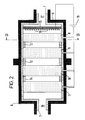
- Figure 2 shows the same sectional view of the scrubbing apparatus shown in Figure 1 in more detail.
- Figure 3 shows a further sectional view of the scrubbing apparatus of Figure 1 and 2 along the lines III-III of Figure 2 in particular.
- Figure 4 shows IN characteristics for the apparatus shown in Figure 2.
- Figure 1 apparatus for carrying out a process of the invention. it shows in process chamber 1 in which a semiconductor processing can take place and exhaust ducts 2, 3 leading to a vacuum pump system 4 which can comprise one or more vacuum pumps, typically a turbomolecular pump backed with a separate mechanical dry pump acting in tandem.
- a vacuum pump system 4 which can comprise one or more vacuum pumps, typically a turbomolecular pump backed with a separate mechanical dry pump acting in tandem.
- a scrubbing apparatus 5 Positioned between the exhaust ducts 2, 3 is a scrubbing apparatus 5 for carrying out a process of the invention.
- the scrubbing apparatus 5 is shown in more detail in Figure 2. It comprises a substantially cylindrical body having a multi-piece outer shell 6 within which is an electrically non-conductive multi-piece inner shell 7.
- the inner shell 7 supports four cylindrical stainless steel blocks 8, 9, 10, 11.
- Each of the four stainless steel blocks 8, 9, 10, 11 has formed therein a plurality - one hundred and nine - of bores of axial orientation as shown more clearly in the further sectional view of Figure 3.
- Each block 8, 9, 10, 11 has a diameter of 100mm and a length of 50mm with each bore - open at both ends - having a diameter of 10 mm.
- Annular insulating elements 12, 13, 14 provide further insulation between the blocks 8, 9, 10, 11.
- the insulating inner shell 7 also supports a substantially ring shaped anode 15 having an outer diameter approximately the same as the internal diameter of the shell 7 and a thickness of about 5mm.
- a multiplicity of anode points 16 extend from the anode 15 in the direction of the outer periphery of the near flat face of the block 8. Such anode points can assist in maintaining the plasma - and a hollow cathode effect - in each of the bores.
- the shells 6, 7 have found therein a gas inlet 17 and a gas outlet 18.
- a power source 19 is provided to charge each of the blocks 8, 9, 10, 11 to a cathode (negative) potential and the anode 15 to an anode (positive) potential.
- argon gas was introduced into the duct 2 between the process chamber 1 and the scrubbing apparatus 5 at a rate of 30 to 40 standard cm 3 /min and, by virtue of the operation of the vacuum pump system 4, is urged through the scrubbing apparatus 5. It should be noted that this flow rate can be of the order of several, for example 2 to 3, litres/minute.
- a variable voltage was provided from the power source 19 in the form of a rectified AC supply via a full wave bridge from a high reactance transformer such that arcs are not sustained.
- methane gas was caused to flow from the process chamber and mix with the argon supply introducing an argon/methane gas mixture in to the individual bores of the blocks 8, 9, 10, 11 moved the onset of the saturation voltage to over 400v and resulted in the decomposition of the methane component of the gas mixture in to a graphitic powder within the hollow cathode bores.
- methane in the above illustration of the invention demonstrates the effective scrubbing of strongly bonded molecules, the C-H bond in methane being particularly strong.
- the process of the invention may be carried out in a simpler form of apparatus, for example one having a single cathode block of conducting material which, together with a suitable anode, is held within an insulating body and adapted to receive a DC supply or alternatively an AC or rectified AC supply to maintain a potential across the system and to form the hollow cathode effect in the bores of the cathode block.
- the cathode can be-similar to that shown and described with reference to figure 2 in particular.
- gases employed in semiconductor processing include chlorine, silicon tetrachloride, copper chloride (CuCI), aluminium chlorides (eg AlCl 3 ), silicon tetrafluoride (SiF 4 ), trifluoromethane (CHF 3 ), carbonyl fluoride (COF 2 ), carbonyl chloride (COCl 2 ), boron trichloride (BCl 3 ), boron tribromide (BBr 3 ), hydrogen chloride (HCI), carbon tetrachloride (CCl 4 ), silane (SiH 4 ), dichlorosilane (SiCl 2 H 2 ), tetraethylorthosilicate (Si(OC 2 H
- Apparatus for use in the process of the invention can be usefully employed as a stand alone piece of apparatus or for incorporation in to or specific components for use in conjunction with vacuum pumps, for example for use in the vicinity of the inlet to such a pump or for use between the stages of a multi-stage pump or, indeed, between two different vacuum, pumps.
- the fact that the apparatus is designed to operate, and must be operated, at low pressure means that it is particularly suitable for use at some point prior to the final exhaust of the gas stream from the vacuum pump system as a whole.
Landscapes
- Chemical & Material Sciences (AREA)
- Engineering & Computer Science (AREA)
- Analytical Chemistry (AREA)
- General Chemical & Material Sciences (AREA)
- Oil, Petroleum & Natural Gas (AREA)
- Chemical Kinetics & Catalysis (AREA)
- Treating Waste Gases (AREA)
Abstract
Description
Claims (8)
- A process for the scrubbing of undesirable substances from an exhaust gas stream which comprises passing the stream through a hollow cathode.
- A process according to Claim 1 in which the hollow cathode is a hollow cylindrical tube.
- A process according to Claim 1 or Claim 2 in which the process is carried out in apparatus comprising a plurality of hollow cathodes arranged in an array such that the stream is passed through the cathodes in parallel.
- A process according to Claim 4 in which cathode tubes are formed as a plurality of bores in a solid electrically conductive body.
- A process according to Claim 4 in which the electrically conductive body is of stainless steel.
- A process according to Claim 4 in which the electrically conductive body is of copper.
- A process according to any one of Claims 3 to 6 in which one array of hollow cathodes is employed.
- A process according to any one of Claims 3 to 6 in which more than one array of hollow cathodes is employed such that the exhaust gas stream passes through each array in series.
Applications Claiming Priority (2)
| Application Number | Priority Date | Filing Date | Title |
|---|---|---|---|
| GBGB9615859.7A GB9615859D0 (en) | 1996-07-29 | 1996-07-29 | Processes and apparatus for the scrubbing of exhaust gas streams |
| GB9615859 | 1996-07-29 |
Publications (2)
| Publication Number | Publication Date |
|---|---|
| EP0821995A1 true EP0821995A1 (en) | 1998-02-04 |
| EP0821995B1 EP0821995B1 (en) | 2003-01-22 |
Family
ID=10797649
Family Applications (1)
| Application Number | Title | Priority Date | Filing Date |
|---|---|---|---|
| EP97305370A Expired - Lifetime EP0821995B1 (en) | 1996-07-29 | 1997-07-18 | Processes and apparatus for the scrubbing of exhaust gas streams |
Country Status (5)
| Country | Link |
|---|---|
| US (1) | US5951742A (en) |
| EP (1) | EP0821995B1 (en) |
| JP (1) | JPH10128039A (en) |
| DE (1) | DE69718571T2 (en) |
| GB (1) | GB9615859D0 (en) |
Cited By (8)
| Publication number | Priority date | Publication date | Assignee | Title |
|---|---|---|---|---|
| WO2000077452A1 (en) | 1999-06-16 | 2000-12-21 | Centrotherm Elektrische Anlagen Gmbh + Co. | Emission control system |
| WO2001091889A1 (en) * | 2000-06-02 | 2001-12-06 | Emitec Gesellschaft Für Emissionstechnologie Mbh | Compact plasma reactor |
| FR2834226A1 (en) * | 2001-12-28 | 2003-07-04 | St Microelectronics Sa | Low pressure pyrolysis process, used e.g. in the fabrication of electronic devices on semiconductor wafers, involves passing a reactive gas at low pressure into a container and forming a reactive gas plasma at container outlet |
| WO2008001129A1 (en) | 2006-06-28 | 2008-01-03 | Edwards Limited | Method and apparatus for treating a gas stream |
| DE202013003819U1 (en) * | 2013-04-24 | 2014-07-25 | Oerlikon Leybold Vacuum Gmbh | Vacuum system |
| CN103961973A (en) * | 2014-05-09 | 2014-08-06 | 常州友达环保科技有限公司 | Adsorption device with built-in electric filter |
| EP2923751A1 (en) * | 2014-03-17 | 2015-09-30 | Ebara Corporation | Multi-stage vacuum pump with abatement function |
| EP2933007A1 (en) * | 2014-03-17 | 2015-10-21 | Ebara Corporation | Vacuum pump with abatement function |
Families Citing this family (14)
| Publication number | Priority date | Publication date | Assignee | Title |
|---|---|---|---|---|
| US7318856B2 (en) * | 1998-11-05 | 2008-01-15 | Sharper Image Corporation | Air treatment apparatus having an electrode extending along an axis which is substantially perpendicular to an air flow path |
| US6262359B1 (en) * | 1999-03-17 | 2001-07-17 | Ebara Solar, Inc. | Aluminum alloy back junction solar cell and a process for fabrication thereof |
| US6302944B1 (en) * | 1999-04-23 | 2001-10-16 | Stuart Alfred Hoenig | Apparatus for extracting water vapor from air |
| SE516722C2 (en) * | 1999-04-28 | 2002-02-19 | Hana Barankova | Process and apparatus for plasma gas treatment |
| US6585803B1 (en) * | 2000-05-11 | 2003-07-01 | University Of Southern California | Electrically enhanced electrostatic precipitator with grounded stainless steel collector electrode and method of using same |
| FR2818451B1 (en) * | 2000-12-18 | 2007-04-20 | Jean Marie Billiotte | ELECTROSTATIC ION EMISSION DEVICE FOR DEPOSITING A QUASI HOMOGENEOUS AMOUNT OF IONS ON THE SURFACE OF A MULTITUDE OF AEROSOL PARTICLES WITHIN A MOVING FLUID. |
| US8340979B2 (en) * | 2002-10-01 | 2012-12-25 | Acs State & Local Solutions, Inc. | Systems and methods for electronically processing government sponsored benefits |
| KR100506506B1 (en) * | 2003-07-11 | 2005-08-05 | 위순임 | Plasma dry scrubber |
| JP2009506881A (en) * | 2005-07-29 | 2009-02-19 | ユニバーシティ オブ デラウェア | Hollow cathode plasma source for biological and chemical decontamination of air and surfaces |
| US8246720B2 (en) * | 2007-07-31 | 2012-08-21 | Cfd Research Corporation | Electrostatic aerosol concentrator |
| US8673068B2 (en) * | 2008-09-18 | 2014-03-18 | Elena Vladimirovna Volodina | Device for inactivating and finely filtering viruses and microorganisms in a flow of air |
| CN103785540A (en) * | 2014-02-18 | 2014-05-14 | 佛山市科蓝环保科技股份有限公司 | Novel honeycomb electric field structure |
| CN106731542B (en) * | 2016-12-26 | 2024-03-26 | 浙江工商大学 | Electrochemical treatment device and method for phosphine gas |
| CN108097009A (en) * | 2018-01-02 | 2018-06-01 | 昆明理工大学 | It is a kind of to purify phosphine gas and the method for recycling phosphoric acid in uncontrollable discharge environment |
Citations (5)
| Publication number | Priority date | Publication date | Assignee | Title |
|---|---|---|---|---|
| GB1340195A (en) * | 1970-06-22 | 1973-12-12 | Nigol O | Separation and removal of selected gas components from gaseous mixtures |
| EP0343987A2 (en) * | 1988-05-26 | 1989-11-29 | MITSUI TOATSU CHEMICALS, Inc. | Exhaust gas treating apparatus |
| EP0379760A1 (en) * | 1989-01-26 | 1990-08-01 | Univerzita Komenskeho | Device for continuously reducing concentration of carbon monoxide and other harmful types of emission |
| WO1993013851A1 (en) * | 1992-01-16 | 1993-07-22 | Leybold B.V. | Method, dry multi-stage pump and plasma scrubber for converting reactive gases |
| EP0296720B1 (en) * | 1987-06-23 | 1994-07-27 | Kin-Chung Ray Chiu | Plasma extraction reactor and its use for vapor extraction from gases |
Family Cites Families (12)
| Publication number | Priority date | Publication date | Assignee | Title |
|---|---|---|---|---|
| CA563130A (en) * | 1958-09-09 | J. Maas Friedrich | Electrostatic precipitator | |
| US1357202A (en) * | 1915-09-16 | 1920-10-26 | Int Precipitation Co | Art of producing electrical precipitation of particles from fluid or gaseous streams |
| GB662537A (en) * | 1948-11-26 | 1951-12-05 | Power Jets Res & Dev Ltd | Improvements in or relating to gas cleaners |
| US3431411A (en) * | 1964-05-28 | 1969-03-04 | Philips Corp | Infrared spectra of powders by means of internal reflection spectroscopy |
| US3679973A (en) * | 1970-10-20 | 1972-07-25 | Us Interior | Electrogasdynamic dust monitor |
| US4072477A (en) * | 1972-05-11 | 1978-02-07 | The Regents Of The University Of California | Electrostatic precipitation process |
| US4077785A (en) * | 1977-05-09 | 1978-03-07 | Research-Cottrell, Inc. | Corrosion resistant electrostatic precipitator |
| DE3501155A1 (en) * | 1985-01-16 | 1986-07-17 | Metallgesellschaft Ag, 6000 Frankfurt | SPRAY AND DEPOSITION ELECTRODES FOR ELECTROFILTER |
| DE4200343C2 (en) * | 1992-01-09 | 1993-11-11 | Metallgesellschaft Ag | Electrostatic separator |
| US5395430A (en) * | 1993-02-11 | 1995-03-07 | Wet Electrostatic Technology, Inc. | Electrostatic precipitator assembly |
| CA2108539C (en) * | 1993-10-15 | 1999-01-26 | Constantinos J. Joannou | Ionizing type air cleaner |
| US5614002A (en) * | 1995-10-24 | 1997-03-25 | Chen; Tze L. | High voltage dust collecting panel |
-
1996
- 1996-07-29 GB GBGB9615859.7A patent/GB9615859D0/en active Pending
-
1997
- 1997-07-18 DE DE69718571T patent/DE69718571T2/en not_active Expired - Lifetime
- 1997-07-18 EP EP97305370A patent/EP0821995B1/en not_active Expired - Lifetime
- 1997-07-23 US US08/899,240 patent/US5951742A/en not_active Expired - Lifetime
- 1997-07-29 JP JP9202806A patent/JPH10128039A/en active Pending
Patent Citations (5)
| Publication number | Priority date | Publication date | Assignee | Title |
|---|---|---|---|---|
| GB1340195A (en) * | 1970-06-22 | 1973-12-12 | Nigol O | Separation and removal of selected gas components from gaseous mixtures |
| EP0296720B1 (en) * | 1987-06-23 | 1994-07-27 | Kin-Chung Ray Chiu | Plasma extraction reactor and its use for vapor extraction from gases |
| EP0343987A2 (en) * | 1988-05-26 | 1989-11-29 | MITSUI TOATSU CHEMICALS, Inc. | Exhaust gas treating apparatus |
| EP0379760A1 (en) * | 1989-01-26 | 1990-08-01 | Univerzita Komenskeho | Device for continuously reducing concentration of carbon monoxide and other harmful types of emission |
| WO1993013851A1 (en) * | 1992-01-16 | 1993-07-22 | Leybold B.V. | Method, dry multi-stage pump and plasma scrubber for converting reactive gases |
Cited By (12)
| Publication number | Priority date | Publication date | Assignee | Title |
|---|---|---|---|---|
| WO2000077452A1 (en) | 1999-06-16 | 2000-12-21 | Centrotherm Elektrische Anlagen Gmbh + Co. | Emission control system |
| US7438869B1 (en) | 1999-06-16 | 2008-10-21 | Centrotherm Clean Solutions Gmbh + Co. Kg | Emission control system |
| WO2001091889A1 (en) * | 2000-06-02 | 2001-12-06 | Emitec Gesellschaft Für Emissionstechnologie Mbh | Compact plasma reactor |
| US6787002B2 (en) | 2000-06-02 | 2004-09-07 | Emitec Gesellschaft Fuer Emissionstechnologie Mbh | Compact plasma reactor |
| FR2834226A1 (en) * | 2001-12-28 | 2003-07-04 | St Microelectronics Sa | Low pressure pyrolysis process, used e.g. in the fabrication of electronic devices on semiconductor wafers, involves passing a reactive gas at low pressure into a container and forming a reactive gas plasma at container outlet |
| WO2008001129A1 (en) | 2006-06-28 | 2008-01-03 | Edwards Limited | Method and apparatus for treating a gas stream |
| DE202013003819U1 (en) * | 2013-04-24 | 2014-07-25 | Oerlikon Leybold Vacuum Gmbh | Vacuum system |
| EP2923751A1 (en) * | 2014-03-17 | 2015-09-30 | Ebara Corporation | Multi-stage vacuum pump with abatement function |
| EP2933007A1 (en) * | 2014-03-17 | 2015-10-21 | Ebara Corporation | Vacuum pump with abatement function |
| US10641272B2 (en) | 2014-03-17 | 2020-05-05 | Ebara Corporation | Vacuum pump with abatement function |
| US10641256B2 (en) | 2014-03-17 | 2020-05-05 | Ebara Corporation | Vacuum pump with abatement function |
| CN103961973A (en) * | 2014-05-09 | 2014-08-06 | 常州友达环保科技有限公司 | Adsorption device with built-in electric filter |
Also Published As
| Publication number | Publication date |
|---|---|
| DE69718571T2 (en) | 2003-07-31 |
| US5951742A (en) | 1999-09-14 |
| DE69718571D1 (en) | 2003-02-27 |
| GB9615859D0 (en) | 1996-09-11 |
| JPH10128039A (en) | 1998-05-19 |
| EP0821995B1 (en) | 2003-01-22 |
Similar Documents
| Publication | Publication Date | Title |
|---|---|---|
| EP0821995B1 (en) | Processes and apparatus for the scrubbing of exhaust gas streams | |
| US11185815B2 (en) | Plasma abatement of compounds containing heavy atoms | |
| KR102435471B1 (en) | Hall effect enhanced capacitively coupled plasma source, an abatement system, and vacuum processing system | |
| EP1715937B1 (en) | Methods and apparatuses for treating a fluorocompound-containing gas stream | |
| KR100945038B1 (en) | Plasma reactor and plasma scrubber using the same | |
| CN105026612B (en) | Gas sleeve pipe for foreline plasma abatement system | |
| US6576573B2 (en) | Atmospheric pressure plasma enhanced abatement of semiconductor process effluent species | |
| US20160118226A1 (en) | Hall effect enhanced capacitively coupled plasma source | |
| US5292396A (en) | Plasma processing chamber | |
| KR101642129B1 (en) | Plasma reactor for eco_frindly processing | |
| TW201021902A (en) | System for eliminating waste gases by making use of plasmas at low and atmospheric pressure | |
| US5779991A (en) | Apparatus for destroying hazardous compounds in a gas stream | |
| US20090301298A1 (en) | Apparatus for Treating a Gas Stream | |
| KR20180011477A (en) | Method and apparatus for reducing ignition byproducts from an ion implantation process | |
| Yamamoto et al. | Synthesis of ultrafine particles by surface discharge-induced plasma chemical process (SPCP) and its application | |
| JPH0480723B2 (en) | ||
| JP2002210330A (en) | Waste gas treatment apparatus for semiconductor processing | |
| JP2002085939A (en) | Decomposition treatment process of fluorine-based waste gas | |
| KR100365666B1 (en) | particle removal and chlorofluorocarbons compound decomposition system using middle frequency plasma source | |
| JP2004033945A (en) | Exhaust gas treatment apparatus and exhaust gas treating method | |
| JPH10309431A (en) | Apparatus for decomposing hazardous compound in polluted gas in gas system | |
| KR20200008444A (en) | Plasma reactor |
Legal Events
| Date | Code | Title | Description |
|---|---|---|---|
| PUAI | Public reference made under article 153(3) epc to a published international application that has entered the european phase |
Free format text: ORIGINAL CODE: 0009012 |
|
| AK | Designated contracting states |
Kind code of ref document: A1 Designated state(s): AT BE CH DE DK ES LI |
|
| AX | Request for extension of the european patent |
Free format text: AL;LT;LV;RO;SI |
|
| 17P | Request for examination filed |
Effective date: 19980731 |
|
| AKX | Designation fees paid |
Free format text: AT BE CH DE DK ES LI |
|
| RBV | Designated contracting states (corrected) |
Designated state(s): AT BE CH DE DK ES LI |
|
| RBV | Designated contracting states (corrected) |
Designated state(s): CH DE FR GB IT LI NL |
|
| 17Q | First examination report despatched |
Effective date: 20010426 |
|
| GRAG | Despatch of communication of intention to grant |
Free format text: ORIGINAL CODE: EPIDOS AGRA |
|
| GRAG | Despatch of communication of intention to grant |
Free format text: ORIGINAL CODE: EPIDOS AGRA |
|
| GRAH | Despatch of communication of intention to grant a patent |
Free format text: ORIGINAL CODE: EPIDOS IGRA |
|
| GRAH | Despatch of communication of intention to grant a patent |
Free format text: ORIGINAL CODE: EPIDOS IGRA |
|
| GRAA | (expected) grant |
Free format text: ORIGINAL CODE: 0009210 |
|
| AK | Designated contracting states |
Kind code of ref document: B1 Designated state(s): CH DE FR GB IT LI NL |
|
| PG25 | Lapsed in a contracting state [announced via postgrant information from national office to epo] |
Ref country code: NL Free format text: LAPSE BECAUSE OF FAILURE TO SUBMIT A TRANSLATION OF THE DESCRIPTION OR TO PAY THE FEE WITHIN THE PRESCRIBED TIME-LIMIT Effective date: 20030122 Ref country code: IT Free format text: LAPSE BECAUSE OF FAILURE TO SUBMIT A TRANSLATION OF THE DESCRIPTION OR TO PAY THE FEE WITHIN THE PRESCRIBED TIME-LIMIT;WARNING: LAPSES OF ITALIAN PATENTS WITH EFFECTIVE DATE BEFORE 2007 MAY HAVE OCCURRED AT ANY TIME BEFORE 2007. THE CORRECT EFFECTIVE DATE MAY BE DIFFERENT FROM THE ONE RECORDED. Effective date: 20030122 |
|
| REG | Reference to a national code |
Ref country code: GB Ref legal event code: FG4D |
|
| REG | Reference to a national code |
Ref country code: CH Ref legal event code: EP |
|
| REG | Reference to a national code |
Ref country code: CH Ref legal event code: NV Representative=s name: RIEDERER HASLER & PARTNER PATENTANWAELTE AG |
|
| REF | Corresponds to: |
Ref document number: 69718571 Country of ref document: DE Date of ref document: 20030227 Kind code of ref document: P |
|
| NLV1 | Nl: lapsed or annulled due to failure to fulfill the requirements of art. 29p and 29m of the patents act | ||
| ET | Fr: translation filed | ||
| PLBE | No opposition filed within time limit |
Free format text: ORIGINAL CODE: 0009261 |
|
| STAA | Information on the status of an ep patent application or granted ep patent |
Free format text: STATUS: NO OPPOSITION FILED WITHIN TIME LIMIT |
|
| 26N | No opposition filed |
Effective date: 20031023 |
|
| REG | Reference to a national code |
Ref country code: GB Ref legal event code: 732E |
|
| REG | Reference to a national code |
Ref country code: CH Ref legal event code: PUE Owner name: EDWARDS LIMITED Free format text: THE BOC GROUP PLC#CHERTSEY ROAD#WINDLESHAM SURREY GU20 6HJ (GB) -TRANSFER TO- EDWARDS LIMITED#MANOR ROYAL#CRAWLEY WEST SUSSEX RH10 9LW (GB) Ref country code: CH Ref legal event code: NV Representative=s name: RIEDERER HASLER & PARTNER PATENTANWAELTE AG |
|
| REG | Reference to a national code |
Ref country code: FR Ref legal event code: TP |
|
| PGFP | Annual fee paid to national office [announced via postgrant information from national office to epo] |
Ref country code: DE Payment date: 20140729 Year of fee payment: 18 Ref country code: CH Payment date: 20140728 Year of fee payment: 18 |
|
| PGFP | Annual fee paid to national office [announced via postgrant information from national office to epo] |
Ref country code: GB Payment date: 20140729 Year of fee payment: 18 Ref country code: FR Payment date: 20140717 Year of fee payment: 18 |
|
| REG | Reference to a national code |
Ref country code: DE Ref legal event code: R119 Ref document number: 69718571 Country of ref document: DE |
|
| REG | Reference to a national code |
Ref country code: CH Ref legal event code: PL |
|
| GBPC | Gb: european patent ceased through non-payment of renewal fee |
Effective date: 20150718 |
|
| PG25 | Lapsed in a contracting state [announced via postgrant information from national office to epo] |
Ref country code: GB Free format text: LAPSE BECAUSE OF NON-PAYMENT OF DUE FEES Effective date: 20150718 Ref country code: LI Free format text: LAPSE BECAUSE OF NON-PAYMENT OF DUE FEES Effective date: 20150731 Ref country code: DE Free format text: LAPSE BECAUSE OF NON-PAYMENT OF DUE FEES Effective date: 20160202 Ref country code: CH Free format text: LAPSE BECAUSE OF NON-PAYMENT OF DUE FEES Effective date: 20150731 |
|
| REG | Reference to a national code |
Ref country code: FR Ref legal event code: ST Effective date: 20160331 |
|
| PG25 | Lapsed in a contracting state [announced via postgrant information from national office to epo] |
Ref country code: FR Free format text: LAPSE BECAUSE OF NON-PAYMENT OF DUE FEES Effective date: 20150731 |