EP0821222B1 - Sensor, insbesondere Temperatursensor, und Spritzgiesswerkzeug zur Herstellung des Sensors - Google Patents
Sensor, insbesondere Temperatursensor, und Spritzgiesswerkzeug zur Herstellung des Sensors Download PDFInfo
- Publication number
- EP0821222B1 EP0821222B1 EP97111089A EP97111089A EP0821222B1 EP 0821222 B1 EP0821222 B1 EP 0821222B1 EP 97111089 A EP97111089 A EP 97111089A EP 97111089 A EP97111089 A EP 97111089A EP 0821222 B1 EP0821222 B1 EP 0821222B1
- Authority
- EP
- European Patent Office
- Prior art keywords
- sensor
- holding part
- transmitter element
- core
- plastic
- Prior art date
- Legal status (The legal status is an assumption and is not a legal conclusion. Google has not performed a legal analysis and makes no representation as to the accuracy of the status listed.)
- Expired - Lifetime
Links
- 238000002347 injection Methods 0.000 title claims description 23
- 239000007924 injection Substances 0.000 title claims description 23
- 238000004519 manufacturing process Methods 0.000 title claims description 8
- 238000001746 injection moulding Methods 0.000 claims description 6
- 230000000149 penetrating effect Effects 0.000 claims description 2
- 238000005538 encapsulation Methods 0.000 description 3
- 238000001125 extrusion Methods 0.000 description 3
- 238000005452 bending Methods 0.000 description 1
- 238000005260 corrosion Methods 0.000 description 1
- 230000007797 corrosion Effects 0.000 description 1
- 238000007765 extrusion coating Methods 0.000 description 1
- 239000000463 material Substances 0.000 description 1
- 238000000034 method Methods 0.000 description 1
- 238000000465 moulding Methods 0.000 description 1
- 238000010137 moulding (plastic) Methods 0.000 description 1
- 210000001331 nose Anatomy 0.000 description 1
- 239000006223 plastic coating Substances 0.000 description 1
- 229920000642 polymer Polymers 0.000 description 1
Images


Classifications
-
- B—PERFORMING OPERATIONS; TRANSPORTING
- B29—WORKING OF PLASTICS; WORKING OF SUBSTANCES IN A PLASTIC STATE IN GENERAL
- B29C—SHAPING OR JOINING OF PLASTICS; SHAPING OF MATERIAL IN A PLASTIC STATE, NOT OTHERWISE PROVIDED FOR; AFTER-TREATMENT OF THE SHAPED PRODUCTS, e.g. REPAIRING
- B29C45/00—Injection moulding, i.e. forcing the required volume of moulding material through a nozzle into a closed mould; Apparatus therefor
- B29C45/14—Injection moulding, i.e. forcing the required volume of moulding material through a nozzle into a closed mould; Apparatus therefor incorporating preformed parts or layers, e.g. injection moulding around inserts or for coating articles
- B29C45/14065—Positioning or centering articles in the mould
-
- B—PERFORMING OPERATIONS; TRANSPORTING
- B29—WORKING OF PLASTICS; WORKING OF SUBSTANCES IN A PLASTIC STATE IN GENERAL
- B29C—SHAPING OR JOINING OF PLASTICS; SHAPING OF MATERIAL IN A PLASTIC STATE, NOT OTHERWISE PROVIDED FOR; AFTER-TREATMENT OF THE SHAPED PRODUCTS, e.g. REPAIRING
- B29C45/00—Injection moulding, i.e. forcing the required volume of moulding material through a nozzle into a closed mould; Apparatus therefor
- B29C45/14—Injection moulding, i.e. forcing the required volume of moulding material through a nozzle into a closed mould; Apparatus therefor incorporating preformed parts or layers, e.g. injection moulding around inserts or for coating articles
- B29C45/14639—Injection moulding, i.e. forcing the required volume of moulding material through a nozzle into a closed mould; Apparatus therefor incorporating preformed parts or layers, e.g. injection moulding around inserts or for coating articles for obtaining an insulating effect, e.g. for electrical components
-
- G—PHYSICS
- G01—MEASURING; TESTING
- G01K—MEASURING TEMPERATURE; MEASURING QUANTITY OF HEAT; THERMALLY-SENSITIVE ELEMENTS NOT OTHERWISE PROVIDED FOR
- G01K7/00—Measuring temperature based on the use of electric or magnetic elements directly sensitive to heat ; Power supply therefor, e.g. using thermoelectric elements
- G01K7/16—Measuring temperature based on the use of electric or magnetic elements directly sensitive to heat ; Power supply therefor, e.g. using thermoelectric elements using resistive elements
- G01K7/22—Measuring temperature based on the use of electric or magnetic elements directly sensitive to heat ; Power supply therefor, e.g. using thermoelectric elements using resistive elements the element being a non-linear resistance, e.g. thermistor
Definitions
- the invention relates to a sensor, in particular a temperature serisor. with one of electrically insulating plastic molded, pre-assembled encoder insert, which a sensor element provided for detecting a measured variable, electrical connections and from the transmitter element to electrical connection elements leading the connections Has.
- the invention further relates to an injection mold with an injection mold and with one in the Injection mold moving core.
- a disadvantage of the known sensor is that it is expensive is built and to be manufactured. For example it is necessary to connect the connecting cables with a high Dimension strength, otherwise the encoder element when encapsulated with plastic very easily from its intended position in the injection mold to a Side can emigrate.
- the invention is based on the problem of a sensor of the type mentioned in such a way that it is as possible is inexpensive to manufacture. Furthermore, a Injection mold with which the sensor is as simple as possible is to be developed.
- the first-mentioned problem is solved by that the sensor has at least one of the connectors up to the encoder element or up to one guided the holding element holding part Has deepening.
- the senor is required for its manufacture especially little plastic so that it is special has low material costs and therefore inexpensive to manufacture is.
- the recess of the sensor is made during the molding process the encoder insert from the core of the injection mold generated.
- the use of the encoder is thus from Core supported so that the emitter element migrates is largely avoided on one side.
- the sensor is particularly low-mass due to the recess, so that, for example, the one designed as a temperature sensor Sensor has a short response time.
- the order the holding part in the sensor has the advantage that Encoder element completely encapsulated by the plastic and thus protected against corrosion and electrical short circuit is.
- the holding part is according to an advantageous development of the invention is particularly easy to encapsulate with plastic, if it is U-shaped and with its base for Encoder element is arranged pointing.
- the holding part is according to another advantageous development of the invention held securely in the plastic, if it has penetrating holes at its base.
- the holding part is according to another advantageous development the invention is particularly streamlined, if it is roof-shaped at its base, with the transmitter element falling slopes is designed.
- the holding part can the invention simply over the connecting lines be pushed without the risk of bending of the connecting lines is when the holding part a hole and an elongated hole for the connection cables of the encoder element. Designed this way pre-assembly of the encoder insert is particularly easy.
- the second problem namely the creation of a Injection mold for manufacturing the sensor with a outer mold and with one in the outer Injection mold movable core, according to the invention solved in that the core on his in the injection mold protruding end a recording to the kraftoder positive fastening of the encoder element or has a holding part holding the transmitter element.
- the pre-assembled encoder insert can be used simply attach to the core.
- the essence is as a component of the injection mold usually special designed to be stable and therefore able to use the encoder particularly well to hold reliably in its intended position.
- the core is easy pull out of the sensor.
- the Attachment of the encoder insert from the core With especially stably designed connecting cables can accommodate of the core also for fastening the encoder insert be formed on the connecting lines.
- the encoder insert can be used according to another advantageous one Further development of the invention is particularly simple fix the intended position on the core if the core for holding the donor insert protruding elevations of the holding part has corresponding notches. When pulling the core out of the sensor the elevations of the holding part are simply sheared off. This Elevations can protrude from the holding part, for example Be noses.
- the connecting lines are also from the core in held an intended position when the core is shooting for the connecting cables to the encoder element has opposite ends. This is the end ends of the connecting leads led out to the sensor for plugging in a signal line connector held an intended position.
- the core can be molded according to the plastic another advantageous development of the invention just pull it out of the sensor when it goes to his free end is tapered.
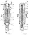
- Figures 1 and 2 each show a longitudinal section trained sensor for measuring a temperature 1.
- the Sensor 1 has a plastic coating 2 Encoder insert 3.
- Encoder insert 3 is one out of one Encoder element 4, a holding part 5 and two connecting lines 6, 7 pre-assembled unit.
- the connecting lines 6, 7 protrude from one end of the sensor 1
- the encoder element 4 is located completely within the plastic extrusion 2 in the end of the sensor 1 facing away from the connections 8, 9. At this point, the plastic extrusion coating 2 the encoder element 4 with one compared to the rest Sensor 1 relatively thin wall thickness.
- a recess 10 extends to the holding part 5.
- This depression 10 is not filled with plastic and tapered to the encoder element 4.
- In the lower end of the recess 10 protrude nose-shaped elevations 11, 12 of the holding part 5.
- plastic molding 2 webs 13, 14 arranged as an anti-rotation serve for the connector of the signal line.
- the Plastic extrusion 2 has an external thread 15 with which the sensor 1 on any, not shown Fasten component.
- FIG 3 shows a sectional view along the Line III - III recognize that the sensor 1 on its outside a hexagon 16 for attaching a not shown Wrench.
- the holding part 5 from FIG. 1 is before an encapsulation shown with plastic in Figures 4 and 5.
- the Holding part 5 is U-shaped, with legs 17, 18 and one Base 19 designed and is in its lower area by Holes 20 penetrated. These holes 20 are like shown in Figure 1 filled with plastic.
- the Legs 17, 18 of the holding part 5 each have the nose-shaped Elevations 11, 12 on.
- the base 19 of the holding part 5 is roof-shaped with sloping downwards Flanks 21, 22 designed and has a bore 23 and an elongated hole 24. Through the bore 23 and the slot 24 are shown in the pre-assembly of the figure 2 Encoder insert 3, the connecting lines 6, 7 out.
- the holding part 5 is made of an electrically insulating Made of plastic.
- FIG. 6 shows part of an injection molding tool with an outer composed of two shells 25, 26 Injection mold 27.
- opening 28 By one at the top of the Injection mold 27 arranged opening 28 can be a movable Core 29 up to one designed as a stop Paragraph 30 are introduced.
- the core has one each Receptacle 34 in the form of a blind hole for the upper ends of the connecting lines shown in Figures 1 and 2 6, 7.
- the core 29 has at its free, in the Injection mold 27 protruding end two opposite Notches 31, 32 and a cone 33.
- the Notches 31, 32 are used to fasten the one in FIG. 1 shown encoder insert 3 on the nose-shaped elevations 11, 12 of the holding part 5.
- the holding part 5 is additional centered by the cone 33 of the core 29. hereby can the encoder insert 3 quickly and reliably attach to the core 29 and into the injection mold 27 insert.
- the core 29 is pulled out of the sensor 1 and leaves the one shown in Figures 1 and 2 Deepening 10.
Landscapes
- Engineering & Computer Science (AREA)
- Manufacturing & Machinery (AREA)
- Mechanical Engineering (AREA)
- Physics & Mathematics (AREA)
- Nonlinear Science (AREA)
- General Physics & Mathematics (AREA)
- Injection Moulding Of Plastics Or The Like (AREA)
- Moulds For Moulding Plastics Or The Like (AREA)
Description
- Fig.1
- einen Längsschnitt durch einen erfindungsgemäßen Sensor,
- Fig.2
- eine Schnittdarstellung durch den Sensor aus Figur 1 entlang der Linie II - II,
- Fig.3
- eine Schnittdarstellung durch den Sensor aus Figur 1 entlang der Linie III - III,
- Fig.4
- eine Schnittdarstellung eines Halteteils aus Figur 1 vor einem Umspritzen mit Kunststoff,
- Fig.5
- eine Schnittdarstellung durch das Halteteil aus Figur 4 entlang der Linie V - V,
- Fig.6
- ein schematische Darstellung eines Teils eines Spritzgießwerkzeuges zur Herstellung des Sensors aus Figur 1.
Claims (9)
- Sensor (1) insbesondere Temperatursensor, mit einem von elektrisch isolierendem Kunststoff umspritzten, vormontierbaren Gebereinsatz (3), welcher ein zur Erfassung einer Meßgröße vorgesehenes Geberelement (4) und von dem Geberelement (4) zu elektrischen Anschlüssen (8, 9) führende elektrische Verbindungselemente (6, 7) hat, dadurch gekennzeichnet, daß der Sensor (1) zumindest eine von den Anschlüssen (8, 9) bis zu dem Geberelement (4) oder bis zu einem das Geberelement (4) haltenden Halteteil (5) geführte nicht mit Kunststoff ausgefüllte Vertiefung (10) hat.
- Sensor nach Anspruch 1, dadurch gekennzeichnet, daß das Halteteil (5) U-förmig gestaltet und mit seiner Basis (19) zum Geberelement (4) weisend angeordnet ist.
- Sensor nach Anspruch 1 oder 2, dadurch gekennzeichnet, daß das Halteteil (5) seine Basis (19) durchdringende Bohrungen (20) hat.
- Sensor nach zumindest einem der vorhergehenden Ansprüche, dadurch gekennzeichnet, daß das Halteteil (5) an seiner Basis (19) dachförmig, mit zum Geberelement (4) hin abfallenden Flanken (21, 22) gestaltet ist.
- Sensor nach zumindest einem der vorhergehenden Ansprüche, dadurch gekennzeichnet, daß das Halteteil (5) eine Bohrung (23) und ein Langloch (24) zur Durchführung der Anschlußleitungen (6, 7) des Geberelements (4) hat.
- Spritzgießwerkzeug zur Herstellung des Sensors (1) nach Anspruch 1 mit einer äußeren Spritzgießform (27) und mit einem durch eine Öffnung (28) der äußeren Spritzgießform (27) in die äußere Spritzgießform (27) hineinbewegbaren Kern (29), dadurch gekennzeichnet, daß der Kern (29) an seinem in die Spritzgießform (27) hineinragenden Ende eine Aufnahme (31, 32, 33) zur kraft- oder formschlüssigen Befestigung des Geberelementes (4) oder eines das Geberelement (4) haltenden Halteteils (5) hat.
- Spritzgießwerkzeug nach Anspruch 6, dadurch gekennzeichnet, daß der Kern (29) zum Haltern des Geberelementes (4) abstehenden Erhebungen (11, 12) des Halteteils (5) entsprechende Einkerbungen (31, 32) aufweist.
- Spritzgießwerkzeug nach Anspruch 6 oder 7, dadurch gekennzeichnet, daß der Kern (29) Aufnahmen (34) für die Anschlußleitungen (6, 7) an ihren dem Geberelement (4) abgewandten Enden aufweist.
- Spritzgießwerkzeug nach zumindest einem der vorhergehenden Ansprüche, dadurch gekennzeichnet, daß der Kern (29) zu seinem freien Ende hin sich verjüngend gestaltet ist.
Applications Claiming Priority (2)
| Application Number | Priority Date | Filing Date | Title |
|---|---|---|---|
| DE19629963A DE19629963A1 (de) | 1996-07-25 | 1996-07-25 | Sensor, insbesondere Temperatursensor, und Spritzgießwerkzeug zur Herstellung des Sensors |
| DE19629963 | 1996-07-25 |
Publications (2)
| Publication Number | Publication Date |
|---|---|
| EP0821222A1 EP0821222A1 (de) | 1998-01-28 |
| EP0821222B1 true EP0821222B1 (de) | 2004-09-22 |
Family
ID=7800759
Family Applications (1)
| Application Number | Title | Priority Date | Filing Date |
|---|---|---|---|
| EP97111089A Expired - Lifetime EP0821222B1 (de) | 1996-07-25 | 1997-07-03 | Sensor, insbesondere Temperatursensor, und Spritzgiesswerkzeug zur Herstellung des Sensors |
Country Status (3)
| Country | Link |
|---|---|
| US (1) | US6151974A (de) |
| EP (1) | EP0821222B1 (de) |
| DE (2) | DE19629963A1 (de) |
Families Citing this family (6)
| Publication number | Priority date | Publication date | Assignee | Title |
|---|---|---|---|---|
| DE29820206U1 (de) * | 1998-11-11 | 1999-02-25 | Microlife Medical Science Asia, Ltd., Shihlin, Taipeh | Elektronisches Fieberthermometer |
| DE50113586D1 (de) * | 2001-01-04 | 2008-03-27 | Vwh Vorrichtungs Und Werkzeugb | Verfahren zum Herstellen eines elektrischen Bauteils sowie diesbezügliches Bauteil |
| US6607302B2 (en) * | 2001-09-24 | 2003-08-19 | Visteon Global Technologies, Inc. | Temperature sensor housing design |
| US20060222050A1 (en) * | 2005-03-31 | 2006-10-05 | Robertshaw Controls Company | Ceramic receptacle for temperature probes and the like |
| DE102008029192A1 (de) | 2008-03-13 | 2009-09-24 | Epcos Ag | Fühler zum Erfassen einer physikalischen Größe und Verfahren zur Herstellung des Fühlers |
| JP5455454B2 (ja) * | 2009-06-08 | 2014-03-26 | 矢崎総業株式会社 | 簡便固定機能付き温度センサとそれの搭載された電池パック送風用エアダクト |
Family Cites Families (7)
| Publication number | Priority date | Publication date | Assignee | Title |
|---|---|---|---|---|
| FR2595819B1 (fr) * | 1986-03-14 | 1988-07-29 | Ciapem | Capteur gaine de temperature |
| US4841274A (en) * | 1987-12-21 | 1989-06-20 | Therm-O-Disc, Incorporated | Temperature responsive probe apparatus |
| US5046857A (en) * | 1990-05-23 | 1991-09-10 | General Motors Corporation | Plastic thermal probe assembly with press fit sensor |
| DE4117290C2 (de) * | 1991-05-27 | 2000-05-31 | Mannesmann Vdo Ag | Temperaturgeber |
| JP2858220B2 (ja) * | 1994-09-13 | 1999-02-17 | 川惣電機工業株式会社 | 温度測定装置における測温センサーエレメント |
| JP3205221B2 (ja) * | 1995-06-02 | 2001-09-04 | 三菱電機株式会社 | 流体の温度センサの製造方法 |
| US5818224A (en) * | 1995-10-13 | 1998-10-06 | Bently Nevada Corporation | Encapsulated transducer with an integrally formed full length sleeve and a component alignment preform and method of manufacture |
-
1996
- 1996-07-25 DE DE19629963A patent/DE19629963A1/de not_active Withdrawn
-
1997
- 1997-07-03 DE DE59711936T patent/DE59711936D1/de not_active Expired - Lifetime
- 1997-07-03 EP EP97111089A patent/EP0821222B1/de not_active Expired - Lifetime
- 1997-07-22 US US08/898,500 patent/US6151974A/en not_active Expired - Lifetime
Also Published As
| Publication number | Publication date |
|---|---|
| EP0821222A1 (de) | 1998-01-28 |
| US6151974A (en) | 2000-11-28 |
| DE19629963A1 (de) | 1998-01-29 |
| DE59711936D1 (de) | 2004-10-28 |
Similar Documents
| Publication | Publication Date | Title |
|---|---|---|
| DE19580281C2 (de) | Magnetsensor | |
| DE4237224C2 (de) | Temperaturfühler | |
| EP1806564B1 (de) | Gehäuseabschluss für Elektronikgehäuse und Verfahren zu dessen Herstellung | |
| DE102011087328B4 (de) | Verfahren zur Herstellung einer umspritzten Sensorbaugruppe sowie eine Sensorbaugruppe | |
| DE3904069A1 (de) | Wasserdichter stopfen fuer eine elektrische steckverbindung | |
| DE10350763A1 (de) | Koaxialkabel mit Winkelsteckverbindung | |
| EP1239266A2 (de) | Verfahren zur Herstellung eines Gehäuses für Sensorelemente, sowie Sensor, und dessen Verwendung | |
| EP1286419A2 (de) | Elektrischer Steckverbinder | |
| DE102012211701A1 (de) | Messwiderstand für Stromsensor und Stromsensoreinheit | |
| DE3840678C1 (en) | Plug connector | |
| DE4117290C2 (de) | Temperaturgeber | |
| DE102008061926B4 (de) | Langgestrecktes Metallelement zur Einspritzung in ein Bauteil | |
| EP0821222A1 (de) | Sensor, insbesondere Temperatursensor und Spritzgiesswerkzeug zur Herstellung des Sensors | |
| DE102009046870B4 (de) | Elektronisches Schaltgerät mit Anschlusskabel | |
| EP1239273A1 (de) | Sensor, insbesondere Temperatur-Sensor | |
| EP0083350A1 (de) | Einführung einer anschlussleitung in ein elektrisches gerät. | |
| EP2250010B1 (de) | Fühler zum erfassen einer physikalischen grösse und verfahren zur herstellung des fühlers | |
| DE102010030958A1 (de) | Anordnung, insbesondere Stecker und Verfahren zur Herstellung | |
| DE10116019B4 (de) | Sensor sowie Verfahren zu dessen Herstellung | |
| DE102021210177A1 (de) | Sensormodul | |
| DE4207850C2 (de) | Elektrische Gerätesteckdose | |
| DE4309028B4 (de) | Geber und Verfahren zur Herstellung eines Gebers | |
| DE69204715T2 (de) | Flüssigkeitstemperatursensor mit integriertem Verbinder. | |
| EP4515631A1 (de) | Massekontaktmodul für ein steuergerät sowie steuergerät und montageverfahren | |
| DE2027785A1 (de) | Stecker |
Legal Events
| Date | Code | Title | Description |
|---|---|---|---|
| PUAI | Public reference made under article 153(3) epc to a published international application that has entered the european phase |
Free format text: ORIGINAL CODE: 0009012 |
|
| 17P | Request for examination filed |
Effective date: 19971120 |
|
| AK | Designated contracting states |
Kind code of ref document: A1 Designated state(s): AT BE CH DE DK ES FI FR GB GR IE IT LI LU MC NL PT SE |
|
| RBV | Designated contracting states (corrected) |
Designated state(s): DE FR GB |
|
| RAP1 | Party data changed (applicant data changed or rights of an application transferred) |
Owner name: SIEMENS AKTIENGESELLSCHAFT |
|
| GRAP | Despatch of communication of intention to grant a patent |
Free format text: ORIGINAL CODE: EPIDOSNIGR1 |
|
| GRAS | Grant fee paid |
Free format text: ORIGINAL CODE: EPIDOSNIGR3 |
|
| GRAA | (expected) grant |
Free format text: ORIGINAL CODE: 0009210 |
|
| AK | Designated contracting states |
Kind code of ref document: B1 Designated state(s): DE FR GB |
|
| PG25 | Lapsed in a contracting state [announced via postgrant information from national office to epo] |
Ref country code: GB Free format text: LAPSE BECAUSE OF FAILURE TO SUBMIT A TRANSLATION OF THE DESCRIPTION OR TO PAY THE FEE WITHIN THE PRESCRIBED TIME-LIMIT Effective date: 20040922 |
|
| REG | Reference to a national code |
Ref country code: GB Ref legal event code: FG4D Free format text: NOT ENGLISH |
|
| REF | Corresponds to: |
Ref document number: 59711936 Country of ref document: DE Date of ref document: 20041028 Kind code of ref document: P |
|
| GBV | Gb: ep patent (uk) treated as always having been void in accordance with gb section 77(7)/1977 [no translation filed] |
Effective date: 20040922 |
|
| PLBE | No opposition filed within time limit |
Free format text: ORIGINAL CODE: 0009261 |
|
| STAA | Information on the status of an ep patent application or granted ep patent |
Free format text: STATUS: NO OPPOSITION FILED WITHIN TIME LIMIT |
|
| ET | Fr: translation filed | ||
| 26N | No opposition filed |
Effective date: 20050623 |
|
| REG | Reference to a national code |
Ref country code: FR Ref legal event code: TP |
|
| PGFP | Annual fee paid to national office [announced via postgrant information from national office to epo] |
Ref country code: DE Payment date: 20140731 Year of fee payment: 18 |
|
| REG | Reference to a national code |
Ref country code: FR Ref legal event code: PLFP Year of fee payment: 19 |
|
| PGFP | Annual fee paid to national office [announced via postgrant information from national office to epo] |
Ref country code: FR Payment date: 20150626 Year of fee payment: 19 |
|
| REG | Reference to a national code |
Ref country code: DE Ref legal event code: R119 Ref document number: 59711936 Country of ref document: DE |
|
| PG25 | Lapsed in a contracting state [announced via postgrant information from national office to epo] |
Ref country code: DE Free format text: LAPSE BECAUSE OF NON-PAYMENT OF DUE FEES Effective date: 20160202 |
|
| PG25 | Lapsed in a contracting state [announced via postgrant information from national office to epo] |
Ref country code: FR Free format text: LAPSE BECAUSE OF NON-PAYMENT OF DUE FEES Effective date: 20160801 |
|
| REG | Reference to a national code |
Ref country code: FR Ref legal event code: ST Effective date: 20170331 |