EP0821137A1 - System zur Erzeugung von Energie - Google Patents
System zur Erzeugung von Energie Download PDFInfo
- Publication number
- EP0821137A1 EP0821137A1 EP97202269A EP97202269A EP0821137A1 EP 0821137 A1 EP0821137 A1 EP 0821137A1 EP 97202269 A EP97202269 A EP 97202269A EP 97202269 A EP97202269 A EP 97202269A EP 0821137 A1 EP0821137 A1 EP 0821137A1
- Authority
- EP
- European Patent Office
- Prior art keywords
- gas
- outlet
- oxygen
- containing gas
- turbine
- Prior art date
- Legal status (The legal status is an assumption and is not a legal conclusion. Google has not performed a legal analysis and makes no representation as to the accuracy of the status listed.)
- Withdrawn
Links
Images


Classifications
-
- F—MECHANICAL ENGINEERING; LIGHTING; HEATING; WEAPONS; BLASTING
- F01—MACHINES OR ENGINES IN GENERAL; ENGINE PLANTS IN GENERAL; STEAM ENGINES
- F01K—STEAM ENGINE PLANTS; STEAM ACCUMULATORS; ENGINE PLANTS NOT OTHERWISE PROVIDED FOR; ENGINES USING SPECIAL WORKING FLUIDS OR CYCLES
- F01K21/00—Steam engine plants not otherwise provided for
- F01K21/04—Steam engine plants not otherwise provided for using mixtures of steam and gas; Plants generating or heating steam by bringing water or steam into direct contact with hot gas
- F01K21/047—Steam engine plants not otherwise provided for using mixtures of steam and gas; Plants generating or heating steam by bringing water or steam into direct contact with hot gas having at least one combustion gas turbine
Definitions
- the present invention relates to a system for power generation from non-gaseous fuels.
- Such systems generally comprise a turbine system, comprising both gas turbines and steam turbines, and a power generating system.
- the efficiency of the best known systems for power generation from non-gaseous fuels is about 40 -45 %.
- the invention therefore provides a system for power generation from non-gaseous fuels comprising a turbine system and a power generating system connected to said turbine system, wherein the said turbine system comprises:
- the fluid is supplied directly to the oxygen-containing gas in and/or after the compressor means and the cooling is essentially obtained by evaporation of the fluid.
- the exhaust gas from the gas turbine means is expanded to a sub-atmospheric pressure of 0.2 - 0.8 bara.
- the exhaust gases leaving the gas turbine means are cooled and water is condensed out.
- At least part of the exhaust gas from said gas turbine means is recycled to the inlet of the oxygen-containing gas of said compressor means.
- At least part of the exhaust gas from the gas turbine means is used to supply heat for drying of the fuel in a drier.
- an organic fuel is used in said power generating system.
- the flue gas outlet of the combustion means passes through a gas cleaning means.
- the flue gas is cleaned in the combustion means.
- fluid to be supplied to the compressor is atomized in the oxygen-containing gas to be fed to the compressor means.
- Fig. 1-4 flow sheets of power stations according to the present invention.
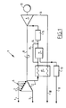
- Fig. 1 shows a power station 1 according to the present invention.
- This power station 1 comprises a compressor unit 2 for quasi-isothermal compression.
- the compressor unit 2 comprises an oxygen-containing gas inlet 3 and a compressed outlet for oxygen-containing gas 4.
- the compressor unit 2 is further provided with means 5 for direct water cooling of oxygen-containing gas in the compressor unit.
- the means 5 comprise a water inlet 6 and waterpipes 7. Furthermore, it is possible to supply water into the compressed oxygen-containing gas outlet 4.
- the compressor unit 2 is mounted on a shaft 8 to which is connected a turbine 9 and a generator 10.
- the compressed oxygen-containing gas outlet 4 is connected to a combustion means 11 to which is also added fuel via a fuel inlet 12 via a fuel pressurizing device 13.
- This fuel is non-gaseous and therefore may consist of particulate fuel, liquid fuel and/or mixtures thereof.
- the flue gas outlet 14 of the combustion unit 11 is provided with a flue gas cleaning unit 15. Subsequently the flue gas is expanded in the turbine 9 and the exhaust gas leaves the turbine 9 via the turbine exhaust gas outlet 16. This outlet 16 passes through a recuperator 17 for heat exchange with compressed oxygen-containing gas that passes through the recuperator 17 via the compressed oxygen-containing gas outlet 4 of the compressor means 2. Finally the cooled exhaust gas is routed to a stack via duct 18.
- a by-pass line 19 may be arranged over the combustion and/or cleaning unit providing an opportunity to control the combustion and/or the turbine temperature.
- Fig. 2 shows a power station 20 of which unit operations and processes similar to those of the power station 1 of Fig. 1 are referred to by using the same reference numbers.
- the compressor means 2 comprises two consecutive compressors 21 and 22 for compressing oxygen-containing gas to respectively 0,8 bara and 8 bara. After each oxygen-containing compression stage water is directly injected for cooling and to that end the direct water cooling means 5 comprise water inlets 23 and 24.
- the fuel supplied via the fuel inlet 12 consists of coal which is combusted at a low pressure of 8 bara and slash is removed from the combustion means 11 via the slash outlet 25.
- the combustion means may consist of a fluidized bed. Cooled flue gas is routed via duct 18 to a stack 32. The efficiency of the power station 20 is about 48.0%.
- the shaft 8 and the generator 10 are omitted for reasons of clarity.
- Fig. 3 shows a power station 26 having a lay-out similar to the power station 20 of Fig. 2. Same or equivalent operation units and processes as for the power station 20 are referred to by the same reference numbers in Fig. 2.
- the power station 26 is provided with a subatmospheric expansion turbine means 27 expanding exhaust gas to a subatmospheric pressure of about 0.5 bara.
- This flue gas passes through the recuperator 17 and subsequently through a condensor unit 28.
- heat and condensate are removed in a cooler 29 and a condensor 30 respectively.
- the cooler 29 may be substituted for another condensor such that two types of condensate may be obtained of which the condensate originating from the condensor 30 is the most pure.
- the dry cool exhaust gas is compressed in a compressor 31 to atmospheric pressure and subsequently released into the atmosphere via the stack 32.
- the power station efficiency is about 50%.
- Fig. 4 shows a power station 33 for firing wet biomass.
- the lay-out of this power station 33 is similar to the power station 20 of Fig. 2 and similar or equivalent unit operations and processes are referred to by the same reference numbers.
- biomass supplied via the biomass inlet 12 is first dried in a biomass dryer 34 using the low temperature heat (about 140°C) of the exhaust gas leaving the recuperator 17 via the outlet 35.
- the dry and heated (110°C) biomass is fed via a pressurizing device 13 to the combustion unit 11. Any combustion ash is removed from the flue gas cleaning unit 15 via the outlet 36.
- the power station efficiency is dependent on the operation parameters about 50 to 54%.
- Fig.5 shows a power station 37 for firing wet biomass.
- the lay-out of this power station 37 is similar to the power station 33 of Fig.4, and similar or equivalent unit operations and processes are referred to by the same reference numbers.
- the water inlet is connected to an atomizing unit 38 for atomizing water in the air fed to the compressor 22 via the air inlet 3.
- Water is atomized in an amount of about 12-15 wt% in the oxygen containing gas in the form of droplets (size 1-5 ⁇ m).
- the power station efficiency is about 55%.
Priority Applications (1)
| Application Number | Priority Date | Filing Date | Title |
|---|---|---|---|
| EP97202269A EP0821137A1 (de) | 1996-07-22 | 1997-07-22 | System zur Erzeugung von Energie |
Applications Claiming Priority (5)
| Application Number | Priority Date | Filing Date | Title |
|---|---|---|---|
| EP96202076 | 1996-07-22 | ||
| EP96202076A EP0821135A1 (de) | 1996-07-22 | 1996-07-22 | Energieerzeugung mittel eines kombinierten Gas- und Kohlekreislaufs |
| EP97200464A EP0821136A1 (de) | 1996-07-22 | 1997-02-17 | System zur Erzeugung von Energie |
| EP97200464 | 1997-02-17 | ||
| EP97202269A EP0821137A1 (de) | 1996-07-22 | 1997-07-22 | System zur Erzeugung von Energie |
Publications (1)
| Publication Number | Publication Date |
|---|---|
| EP0821137A1 true EP0821137A1 (de) | 1998-01-28 |
Family
ID=27237581
Family Applications (1)
| Application Number | Title | Priority Date | Filing Date |
|---|---|---|---|
| EP97202269A Withdrawn EP0821137A1 (de) | 1996-07-22 | 1997-07-22 | System zur Erzeugung von Energie |
Country Status (1)
| Country | Link |
|---|---|
| EP (1) | EP0821137A1 (de) |
Cited By (4)
| Publication number | Priority date | Publication date | Assignee | Title |
|---|---|---|---|---|
| EP0959235A2 (de) | 1998-05-20 | 1999-11-24 | Hitachi, Ltd. | Gasturbinenkraftwerk |
| NL1009484C2 (nl) | 1998-06-24 | 1999-12-27 | Kema Nv | Inrichting voor het comprimeren van een gasvormig medium en systemen die een dergelijke inrichting omvatten. |
| NL1011383C2 (nl) | 1998-06-24 | 1999-12-27 | Kema Nv | Inrichting voor het comprimeren van een gasvormig medium en systemen die een dergelijke inrichting omvatten. |
| EP1609958A1 (de) * | 2004-06-22 | 2005-12-28 | Siemens Aktiengesellschaft | Gasturbine mit einem Verdichter und einem Rekuperator |
Citations (9)
| Publication number | Priority date | Publication date | Assignee | Title |
|---|---|---|---|---|
| GB1056722A (en) * | 1964-01-15 | 1967-01-25 | Arthur Morton Squires | Improvements in or relating to power-generating steam cycle |
| GB1284335A (en) * | 1970-04-15 | 1972-08-09 | Rolls Royce | Improvements in or relating to gas turbine engines |
| US4893469A (en) * | 1988-01-07 | 1990-01-16 | Yasui Yamashita | Steam and combustion gas engine |
| EP0361065A1 (de) * | 1988-09-28 | 1990-04-04 | Westinghouse Electric Corporation | Kraftgenerationsmethode mit festem Brennstoff für eine Gasturbine |
| EP0384336A1 (de) * | 1989-02-22 | 1990-08-29 | Mario Gaia | Verfahren und Vorrichtung zum Umwandeln von thermischer Energie in mechanische Energie |
| EP0444913A1 (de) * | 1990-02-27 | 1991-09-04 | Turbine Developments Aktiengesellschaft | Gasturbine |
| US5067317A (en) * | 1990-02-26 | 1991-11-26 | The United States Of America As Represented By The United State Department Of Energy | Process for generating electricity in a pressurized fluidized-bed combustor system |
| DE4335136A1 (de) * | 1992-10-22 | 1994-04-28 | Evt Energie & Verfahrenstech | Verfahren und Vorrichtung zur Durchführung des Verfahrens zur Erzeugung von Gasen zum Betreiben einer Gasturbine in einem kombinierten Gas- und Dampfkraftwerk |
| EP0602795A2 (de) * | 1992-11-13 | 1994-06-22 | Foster Wheeler Energy Corporation | Kombikraftwerk mit einem Reaktor mit zirkulierender Wirbelschicht |
-
1997
- 1997-07-22 EP EP97202269A patent/EP0821137A1/de not_active Withdrawn
Patent Citations (9)
| Publication number | Priority date | Publication date | Assignee | Title |
|---|---|---|---|---|
| GB1056722A (en) * | 1964-01-15 | 1967-01-25 | Arthur Morton Squires | Improvements in or relating to power-generating steam cycle |
| GB1284335A (en) * | 1970-04-15 | 1972-08-09 | Rolls Royce | Improvements in or relating to gas turbine engines |
| US4893469A (en) * | 1988-01-07 | 1990-01-16 | Yasui Yamashita | Steam and combustion gas engine |
| EP0361065A1 (de) * | 1988-09-28 | 1990-04-04 | Westinghouse Electric Corporation | Kraftgenerationsmethode mit festem Brennstoff für eine Gasturbine |
| EP0384336A1 (de) * | 1989-02-22 | 1990-08-29 | Mario Gaia | Verfahren und Vorrichtung zum Umwandeln von thermischer Energie in mechanische Energie |
| US5067317A (en) * | 1990-02-26 | 1991-11-26 | The United States Of America As Represented By The United State Department Of Energy | Process for generating electricity in a pressurized fluidized-bed combustor system |
| EP0444913A1 (de) * | 1990-02-27 | 1991-09-04 | Turbine Developments Aktiengesellschaft | Gasturbine |
| DE4335136A1 (de) * | 1992-10-22 | 1994-04-28 | Evt Energie & Verfahrenstech | Verfahren und Vorrichtung zur Durchführung des Verfahrens zur Erzeugung von Gasen zum Betreiben einer Gasturbine in einem kombinierten Gas- und Dampfkraftwerk |
| EP0602795A2 (de) * | 1992-11-13 | 1994-06-22 | Foster Wheeler Energy Corporation | Kombikraftwerk mit einem Reaktor mit zirkulierender Wirbelschicht |
Cited By (7)
| Publication number | Priority date | Publication date | Assignee | Title |
|---|---|---|---|---|
| EP0959235A2 (de) | 1998-05-20 | 1999-11-24 | Hitachi, Ltd. | Gasturbinenkraftwerk |
| US6247302B1 (en) | 1998-05-20 | 2001-06-19 | Hitachi, Ltd. | Gas turbine power plant |
| US6397578B2 (en) | 1998-05-20 | 2002-06-04 | Hitachi, Ltd. | Gas turbine power plant |
| NL1009484C2 (nl) | 1998-06-24 | 1999-12-27 | Kema Nv | Inrichting voor het comprimeren van een gasvormig medium en systemen die een dergelijke inrichting omvatten. |
| NL1011383C2 (nl) | 1998-06-24 | 1999-12-27 | Kema Nv | Inrichting voor het comprimeren van een gasvormig medium en systemen die een dergelijke inrichting omvatten. |
| US6453659B1 (en) | 1998-06-24 | 2002-09-24 | N. V. Kema | Device for compressing a gaseous medium and systems comprising such device |
| EP1609958A1 (de) * | 2004-06-22 | 2005-12-28 | Siemens Aktiengesellschaft | Gasturbine mit einem Verdichter und einem Rekuperator |
Similar Documents
| Publication | Publication Date | Title |
|---|---|---|
| US6263661B1 (en) | System for power generation | |
| US4414813A (en) | Power generator system | |
| EP1132594B1 (de) | Zubehör für die energiegewinnung mittels gasturbine und luftbefeuchter | |
| US5678401A (en) | Energy supply system utilizing gas and steam turbines | |
| US20010029732A1 (en) | Process for the recovery of water from the flue gas of a combined cycle power station, and combined cycle power station for performing the process | |
| ATE136359T1 (de) | Trocknungsanlage | |
| RU1838635C (ru) | Способ производства электрической и тепловой энергии | |
| US20060107646A1 (en) | Gas turbine electric power generation equipment and air humidifier | |
| JPH04228832A (ja) | ガスタービン及びその作動方法 | |
| GB2155164A (en) | Heat conservation on the drier section of paper making machines | |
| ITMI941519A1 (it) | Metodo ed apparecchio per aumentare la potenza prodotta da turbina a gas | |
| US4571949A (en) | Cogeneration and sludge drying system | |
| EP0858577B1 (de) | Behandlung eines wasserhaltigen brennstoffs | |
| EP0821137A1 (de) | System zur Erzeugung von Energie | |
| JP2000516315A (ja) | 機械的作業を達成して所望であれば蒸発性ガスタービン処理で熱を発生させる方法および装置 | |
| EP0821136A1 (de) | System zur Erzeugung von Energie | |
| EP0859135A1 (de) | Gasturbine mit Energie-Rückgewinnung | |
| FI80757C (fi) | Kombinerat gasturbins- och aongturbinskraftverk och foerfarande foer att utnyttja braenslets vaerme-energi foer att foerbaettra kraftverksprocessens totala verkningsgrad. | |
| GB2311824A (en) | Gas turbine power plant | |
| FI78137B (fi) | Anordning foer torkning av en bana. | |
| RU2611138C1 (ru) | Способ работы парогазовой установки электростанции | |
| Steinwall | Integration of biomass gasification and evaporative gas turbine cycles | |
| EP2516810B1 (de) | Anordnung in einem gasturbinenverfahren | |
| CA2479985A1 (en) | Enhanced energy conversion system from a fluid heat stream | |
| EP0377723B1 (de) | Trocknungsverfahren in kraftwerken sowie trockner |
Legal Events
| Date | Code | Title | Description |
|---|---|---|---|
| PUAI | Public reference made under article 153(3) epc to a published international application that has entered the european phase |
Free format text: ORIGINAL CODE: 0009012 |
|
| AK | Designated contracting states |
Kind code of ref document: A1 Designated state(s): AT BE CH DE DK ES FI FR GB GR IE IT LI LU MC NL PT SE |
|
| 17P | Request for examination filed |
Effective date: 19980724 |
|
| RBV | Designated contracting states (corrected) |
Designated state(s): AT BE DE DK FI GB IT SE |
|
| 17Q | First examination report despatched |
Effective date: 20010618 |
|
| STAA | Information on the status of an ep patent application or granted ep patent |
Free format text: STATUS: THE APPLICATION IS DEEMED TO BE WITHDRAWN |
|
| 18D | Application deemed to be withdrawn |
Effective date: 20021015 |