EP0820775A2 - Kombinierte Anordnung einer venösen Blut- und einer Kardiotomiekammer in einem extrakorporalen Blutkreislauf - Google Patents
Kombinierte Anordnung einer venösen Blut- und einer Kardiotomiekammer in einem extrakorporalen Blutkreislauf Download PDFInfo
- Publication number
- EP0820775A2 EP0820775A2 EP97111933A EP97111933A EP0820775A2 EP 0820775 A2 EP0820775 A2 EP 0820775A2 EP 97111933 A EP97111933 A EP 97111933A EP 97111933 A EP97111933 A EP 97111933A EP 0820775 A2 EP0820775 A2 EP 0820775A2
- Authority
- EP
- European Patent Office
- Prior art keywords
- reservoir
- blood
- venous
- cardiotomy
- passageway
- Prior art date
- Legal status (The legal status is an assumption and is not a legal conclusion. Google has not performed a legal analysis and makes no representation as to the accuracy of the status listed.)
- Granted
Links
Images

Classifications
-
- G—PHYSICS
- G01—MEASURING; TESTING
- G01N—INVESTIGATING OR ANALYSING MATERIALS BY DETERMINING THEIR CHEMICAL OR PHYSICAL PROPERTIES
- G01N27/00—Investigating or analysing materials by the use of electric, electrochemical, or magnetic means
- G01N27/72—Investigating or analysing materials by the use of electric, electrochemical, or magnetic means by investigating magnetic variables
- G01N27/82—Investigating or analysing materials by the use of electric, electrochemical, or magnetic means by investigating magnetic variables for investigating the presence of flaws
- G01N27/90—Investigating or analysing materials by the use of electric, electrochemical, or magnetic means by investigating magnetic variables for investigating the presence of flaws using eddy currents
- G01N27/904—Investigating or analysing materials by the use of electric, electrochemical, or magnetic means by investigating magnetic variables for investigating the presence of flaws using eddy currents with two or more sensors
-
- A—HUMAN NECESSITIES
- A61—MEDICAL OR VETERINARY SCIENCE; HYGIENE
- A61M—DEVICES FOR INTRODUCING MEDIA INTO, OR ONTO, THE BODY; DEVICES FOR TRANSDUCING BODY MEDIA OR FOR TAKING MEDIA FROM THE BODY; DEVICES FOR PRODUCING OR ENDING SLEEP OR STUPOR
- A61M1/00—Suction or pumping devices for medical purposes; Devices for carrying-off, for treatment of, or for carrying-over, body-liquids; Drainage systems
- A61M1/36—Other treatment of blood in a by-pass of the natural circulatory system, e.g. temperature adaptation, irradiation ; Extra-corporeal blood circuits
- A61M1/3621—Extra-corporeal blood circuits
- A61M1/3627—Degassing devices; Buffer reservoirs; Drip chambers; Blood filters
- A61M1/3632—Combined venous-cardiotomy reservoirs
-
- G—PHYSICS
- G01—MEASURING; TESTING
- G01N—INVESTIGATING OR ANALYSING MATERIALS BY DETERMINING THEIR CHEMICAL OR PHYSICAL PROPERTIES
- G01N27/00—Investigating or analysing materials by the use of electric, electrochemical, or magnetic means
- G01N27/72—Investigating or analysing materials by the use of electric, electrochemical, or magnetic means by investigating magnetic variables
- G01N27/82—Investigating or analysing materials by the use of electric, electrochemical, or magnetic means by investigating magnetic variables for investigating the presence of flaws
- G01N27/90—Investigating or analysing materials by the use of electric, electrochemical, or magnetic means by investigating magnetic variables for investigating the presence of flaws using eddy currents
- G01N27/9013—Arrangements for scanning
- G01N27/902—Arrangements for scanning by moving the sensors
Definitions
- the present invention is in the field of devices for use in surgical procedures. More particularly, the present invention relates to a device having both a venous blood reservoir and a cardiotomy reservoir for use in an extracorporeal circuit.
- Many surgical operations involve circulating the blood of a patient through an extracorporeal circuit.
- many open-heart surgical procedures require that the patient's heart be stopped, and that various biological functions (i.e., blood circulation and oxygenation) be performed mechanically by various devices included in the extracorporeal circuit.
- various biological functions i.e., blood circulation and oxygenation
- devices including oxygenators, heat exchangers, and blood accumulation reservoirs may be employed. Each of these devices is monitored and managed by persons who may be present in the operating room, or at remote monitoring and control stations.
- the venous reservoir serves as a receptacle for blood, typically blood that has been removed from the patient through a vein, which is subsequently oxygenated and further processed prior to being recirculated back to the patient.
- the venous reservoir typically serves to collect blood as it first enters the extracorporeal circuit.
- the use of the venous reservoir enables the operator to control the blood flow rate, blood pressure, blood volume and related parameters necessary to maintaining the patient during the surgical procedure.
- a second type of blood accumulation reservoir used in such procedures is a cardiotomy reservoir.
- the cardiotomy reservoir is used to contain blood which has been collected from the operating field. Blood collected in the cardiotomy reservoir can be reinfused into the patient after being filtered to remove any clots or other unwanted contaminants.
- One object of the present invention is to provide a combined device having both a venous blood reservoir and a cardiotomy reservoir. Another object of the invention is to provide a device which allows venous blood and cardiotomy blood to be optionally integrated if surgical conditions or requirements warrant. Still another object of the invention is to provide a combined venous blood reservoir and cardiotomy reservoir which minimize blood contact with large surface areas of the device and which eliminate the risk of reverse filtration.
- a combined device having a venous blood reservoir and a cardiotomy reservoir.
- the device is characterized in that it includes a housing having a partition which separates a lower reservoir from an upper reservoir.
- the lower reservoir is adapted for use as the venous reservoir
- the upper reservoir is adapted for use as the cardiotomy reservoir.
- the venous reservoir is provided with a blood inlet connector and a blood outlet connector
- the cardiotomy reservoir and is provided with a blood inlet connector and with an air outlet connector.
- Each of the blood inlet connectors is positioned so that blood entering the device is caused to flow through a defoaming substance and a filter.
- the partition which separates the venous reservoir from the cardiotomy reservoir is provided with at least two ducts which, starting from apertures formed in the partition, project upward into the cardiotomy reservoir and reach different elevations therein.
- FIGS. 1-4 One embodiment of the device of the present invention is depicted in FIGS. 1-4.
- FIGS. 2 and 3 a view of the device taken along plane II-II of FIG. 1 is shown.
- the column 16 has been rotated 90° into the page with respect to its position shown in FIG. 1.
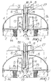
- the reference numeral 1 designates a housing of the device and the reference numeral 2 designates a partition which divides the space enclosed by the housing 1 into a venous reservoir 3, and a cardiotomy reservoir 4.
- the housing is preferably formed of a transparent polymer to allow the interior of the device to be viewed by an operator. Numerous transparent, medically useful polymers are known to those having ordinary skill in the art.
- the venous reservoir 3 is provided with an venous inlet connector 5, terminating at 5a, for the venous blood.
- Venous blood entering the venous reservoir 3 through the venous inlet connector 5 enters a distribution chamber 22 where it is passed outward, in a substantially uniform manner, into a central region of the venous reservoir through a plurality of slotted apertures 23 formed in the distribution chamber 22.
- the central region of the venous reservoir is defined by a generally cylindrical wall 6 of a defoaming material.
- the defoaming material is surrounded by a filter 6a through which the blood must also pass as it enters the venous reservoir 3. Blood exits the venous reservoir 3 through a venous outlet connector 7.
- the defoaming material comprises a porous polymeric material such as a polyurethane foam.
- the defoaming material is a polyurethane foam having a pore size of approximately 5 to 50 pores per inch, more preferably approximately 20 to 30 pores per inch.
- the defoaming material may optionally be treated with a medically acceptable antifoaming agent such as a silicone antifoaming agent.
- the filter is a screen, preferably formed of a polyester, having an aperture size in the range of about 20 to 50 microns.
- the top of the venous reservoir 3 is defined by a partition 2 which separates the venous reservoir 3 from the cardiotomy reservoir 4.
- the cardiotomy reservoir 4 is provided with a cardiotomy inlet connector 8 for receiving blood arriving from the operating field, and an air outlet connector 10. Blood entering the cardiotomy reservoir 4 through the cardiotomy inlet 8 first encounters a flow distributor 24, which distributes the blood outwardly in a substantially uniform manner. As with the blood entering the venous reservoir, the blood next encounters a generally cylindrical wall 9 of a defoaming material. The defoaming material is surrounded by a filter 9a through which the blood must also pass as it enters the cardiotomy reservoir 4.
- the defoaming material is as described above, namely, a porous polymeric material such as a polyurethane foam.
- the defoaming material is a polyurethane foam having a pore size of approximately 5 to 50 pores per inch, more preferably approximately 20 to 30 pores per inch
- the filter is a screen, preferably formed of a polyester, having an aperture size in the range of about 20 to 50 microns.
- the partition 2 which separates the venous and cardiotomy reservoirs is typically a substantially flat plate. When the device is in operation, it is positioned in a manner that maintains the partition in a substantially horizontal orientation.
- the partition 2 is provided with a plurality of apertures that provide for operation of the device in the manner discussed below.
- the partition 2 includes two apertures 11 and 12, from which extend two ducts 13 and 14.
- the ducts preferably extend substantially at right angles to partition 2 and therefore are maintained in a vertical orientation when the device is oriented in its proper operating position.
- the ducts 13 and 14 extend into the cardiotomy reservoir 4 and reach approximately the same elevation.
- the upper edge of each duct is typically provided with a plurality of axial notches 15.
- An axially moveable column 16 is positioned preferably in the center of the cardiotomy reservoir 4 and extends upward through the housing 1.
- the column 16 includes a first passageway 17 and a second passageway 18.
- a lower end 17a communicates with the venous reservoir 3 through a central aperture 20 in the partition 2, and an upper end 17b communicates with the cardiotomy reservoir 4.
- a lower end 18a communicates with the cardiotomy reservoir 4 and an upper end 18b communicates with the exterior of the housing.
- Column 16 can be caused to move axially by manual action on tab 19. As such, the column can be moved between a lower stroke limit position, illustrated in FIGS. 1 and 2, and an upper stroke limit position, shown in FIG. 3. While in the lower stroke position, the lower end 17a of the first passageway is sealingly inserted into a central aperture 20 provided preferably at the center of the partition 2.
- the seal may optionally be enhanced through the use of an O-ring 25 positioned around the exterior of the lower end 17a of the first passageway.
- the seal when engaged, serves to prevent blood in the cardiotomy reservoir from entering the venous reservoir.
- the upper end 17b of the first passageway is caused to be positioned at an elevation which is above that of the upper edges of the ducts 13 and 14.
- a second O-ring 27 may optionally be provided around the exterior of an upper portion of the column 16. The second O-ring 27 serves to provide a seal between the upper portion of the column and the portion of the housing 1 through which the column passes.
- Integration of the venous and cardiotomy reservoirs also allows air and other gaseous emboli entrained in the venous blood, resulting for example from poor cannulation, to be released from the device by passing through the ducts 13, 14 and the first passageway 17 and allowing it to collect in the upper portion of the cardiotomy reservoir 4, from which it may exit or be withdrawn through the air outlet connector 10.
- cardiotomy reservoir 4 is also enhanced. Specifically, blood entering the cardiotomy reservoir 4 through the cardiotomy inlet connector 8 gradually rises in that reservoir until it is almost filled. Rather than completely filling the cardiotomy reservoir, however, once the blood reaches a certain level, it is caused to enter the ducts 13 and 14 and flow downward therethrough, accumulating in the venous reservoir 3. As such, the device is configured to allow excess accumulation of either venous or cardiotomy blood.
- the passageway 17 Since the upper end 17b of the passageway 17 is configured to remain above the upper edges of the ducts 13 and 14, even if the ducts are communicating blood into the venous reservoir, the passageway 17 remains blood-free and capable of communicating air from the venous reservoir into the cardiotomy reservoir, and ultimately, to the exterior of the housing through the air outlet connector 10.
- the central aperture 20 acts as a drainage port which may be plugged and unplugged by the column 16.
- the advantages of the device of the present invention are not intended to be strictly limited to those described above.
- the amount of blood contact with the internal surfaces of the device has been minimized, as has the possibility of reverse filtration of blood contained within the device.
- the device will respond rapidly to control manipulations by the operator.
- the number of ducts provided on the partition can be different from the configuration described.
- the invention is not intended to be limited to the particular materials employed, nor to the shapes or any dimensions employed. Rather, the device may be made according to the specific requirements of a particular application for which its use is intended..
Landscapes
- Health & Medical Sciences (AREA)
- Heart & Thoracic Surgery (AREA)
- Vascular Medicine (AREA)
- Life Sciences & Earth Sciences (AREA)
- General Health & Medical Sciences (AREA)
- Hematology (AREA)
- Engineering & Computer Science (AREA)
- Veterinary Medicine (AREA)
- Public Health (AREA)
- Animal Behavior & Ethology (AREA)
- Chemical & Material Sciences (AREA)
- Biomedical Technology (AREA)
- Cardiology (AREA)
- Anesthesiology (AREA)
- Immunology (AREA)
- Chemical Kinetics & Catalysis (AREA)
- Electrochemistry (AREA)
- Pathology (AREA)
- Analytical Chemistry (AREA)
- General Physics & Mathematics (AREA)
- Physics & Mathematics (AREA)
- Biochemistry (AREA)
- External Artificial Organs (AREA)
- Medical Preparation Storing Or Oral Administration Devices (AREA)
Applications Claiming Priority (2)
| Application Number | Priority Date | Filing Date | Title |
|---|---|---|---|
| ITMI961529 | 1996-07-22 | ||
| IT96MI001529A IT1283482B1 (it) | 1996-07-22 | 1996-07-22 | Dispositivo combinato comprendente serbatoio di sangue venoso e cardiotomo in circuito extracorporeo |
Publications (3)
| Publication Number | Publication Date |
|---|---|
| EP0820775A2 true EP0820775A2 (de) | 1998-01-28 |
| EP0820775A3 EP0820775A3 (de) | 1998-02-11 |
| EP0820775B1 EP0820775B1 (de) | 2003-10-08 |
Family
ID=11374639
Family Applications (1)
| Application Number | Title | Priority Date | Filing Date |
|---|---|---|---|
| EP97111933A Expired - Lifetime EP0820775B1 (de) | 1996-07-22 | 1997-07-14 | Kombinierte Anordnung aus einer Kammer für venöses Blut und einer Kardiotomie-Kammer in einem extrakorporalen Blutkreislauf |
Country Status (8)
| Country | Link |
|---|---|
| US (4) | US6287270B1 (de) |
| EP (1) | EP0820775B1 (de) |
| JP (1) | JP4050808B2 (de) |
| AT (1) | ATE251474T1 (de) |
| AU (1) | AU715388B2 (de) |
| CA (1) | CA2210968A1 (de) |
| DE (1) | DE69725395T2 (de) |
| IT (1) | IT1283482B1 (de) |
Cited By (6)
| Publication number | Priority date | Publication date | Assignee | Title |
|---|---|---|---|---|
| EP1344543A1 (de) * | 2002-03-12 | 2003-09-17 | DIDECO S.p.A. | Venöse Blutkammer in einem extrakorporalen Kreislauf |
| DE10236229A1 (de) * | 2002-05-07 | 2003-11-20 | Maja Medizintechnik Gmbh | Vorrichtung und Verfahren zum Bereitstellen von cardiotomischem oder venösem Blut sowie Herstellungsverfahren eines Blutreservoirs |
| EP1382360A1 (de) * | 2002-07-15 | 2004-01-21 | DIDECO S.p.A. | Hämokonzentrator in einem extrakorporalen Blutkreislauf |
| US10458833B2 (en) | 2014-05-16 | 2019-10-29 | Sorin Group Italia S.R.L. | Blood reservoir with fluid volume measurement based on pressure sensor |
| US11229729B2 (en) | 2009-05-29 | 2022-01-25 | Livanova Deutschland Gmbh | Device for establishing the venous inflow to a blood reservoir of an extracorporeal blood circulation system |
| US11389580B2 (en) | 2011-07-12 | 2022-07-19 | Sorin Group Italia S.R.L. | Dual chamber blood reservoir |
Families Citing this family (22)
| Publication number | Priority date | Publication date | Assignee | Title |
|---|---|---|---|---|
| IT1283482B1 (it) * | 1996-07-22 | 1998-04-21 | Dideco Spa | Dispositivo combinato comprendente serbatoio di sangue venoso e cardiotomo in circuito extracorporeo |
| DE60117556T2 (de) * | 2000-06-21 | 2006-11-02 | Bioarray Solutions Ltd. | Multianalytische molekularanalyse durch verwendung anwendungsspezifischer zufallspartikelarrays |
| DE60126558T2 (de) * | 2000-11-30 | 2007-11-22 | Terumo K.K. | Blutreservoir |
| US7309326B2 (en) * | 2003-11-18 | 2007-12-18 | Icu Medical, Inc. | Infusion set |
| CA2548384C (en) * | 2003-12-10 | 2010-05-04 | Jms Co., Ltd. | Extracorporeal blood circulating apparatus |
| WO2006057650A2 (en) * | 2004-01-22 | 2006-06-01 | Yehuda Tamari | A colsed venous -cardiotomy reservoir with improved air handling |
| US8147440B2 (en) * | 2004-01-22 | 2012-04-03 | Yehuda Tamari | Blood reservoir incorporating a vapor trap |
| SE0402500D0 (sv) * | 2004-10-14 | 2004-10-14 | Astra Tech Ab | Method and apparatus for autotransfusion |
| US8882696B2 (en) | 2005-01-24 | 2014-11-11 | Yehuda Tamari | Blood reservoir with a separate vent and a sucker chambers |
| US7421768B2 (en) * | 2005-08-23 | 2008-09-09 | Chun-Pao Chiang | Fuel hose line installation apparatus |
| ITMI20061187A1 (it) * | 2006-06-20 | 2007-12-21 | Eurosets Srl | Riserva venosa in circuito ematico extracorporeo |
| US8439858B2 (en) * | 2007-10-17 | 2013-05-14 | Medtronic, Inc. | Arterial blood filter |
| DE102009027195A1 (de) | 2009-06-25 | 2010-12-30 | Sorin Group Deutschland Gmbh | Vorrichtung zur Förderung von Blut in einem extrakorporalen Kreislauf |
| ATE554809T1 (de) | 2009-09-21 | 2012-05-15 | Yehuda Tamari | Blutreservoir mit integrierter dampffalle |
| US8506513B2 (en) | 2010-04-20 | 2013-08-13 | Sorin Group Italia S.R.L. | Blood reservoir with ultrasonic volume sensor |
| US8500673B2 (en) | 2010-04-20 | 2013-08-06 | Sorin Group Italia S.R.L. | Blood reservoir with level sensor |
| AU336046S (en) * | 2010-08-17 | 2011-04-18 | Nipro Corp | Blood reservoir with oxygenator |
| US9545472B2 (en) | 2012-03-02 | 2017-01-17 | Medtronic, Inc. | Extracorporeal blood circuit reservoir with angled venous inlet luer port |
| EP3015121B1 (de) | 2014-10-29 | 2017-11-29 | Cardia Innovation AB | Anordnung für einen kardiopulmonalen Bypass |
| US10589198B2 (en) * | 2015-03-20 | 2020-03-17 | Marin Scientific Development Company | High flow, low hold up filters |
| CN109069722B (zh) | 2016-02-29 | 2021-05-28 | 索林集团意大利有限责任公司 | 带有血液处理组件的血液储器 |
| IT201700107088A1 (it) * | 2017-09-25 | 2019-03-25 | Eurosets Srl | Dispositivo per il filtraggio del sangue |
Family Cites Families (26)
| Publication number | Priority date | Publication date | Assignee | Title |
|---|---|---|---|---|
| US3927980A (en) | 1973-08-22 | 1975-12-23 | Baxter Laboratories Inc | Oxygen overpressure protection system for membrane-type blood oxygenators |
| US4006745A (en) | 1975-05-22 | 1977-02-08 | Sorenson Research Co., Inc. | Autologous transfusion system and method |
| US4490331A (en) | 1982-02-12 | 1984-12-25 | Steg Jr Robert F | Extracorporeal blood processing system |
| EP0146708B1 (de) * | 1983-11-11 | 1990-05-23 | TERUMO KABUSHIKI KAISHA trading as TERUMO CORPORATION | Einrichtung zum Aufnehmen und Behandeln von Blut |
| US4642089A (en) | 1985-01-29 | 1987-02-10 | Shiley, Inc. | Unitary venous return reservoir with cardiotomy filter |
| US4876066A (en) | 1986-07-14 | 1989-10-24 | Baxter International Inc. | Integrated membrane oxygenator, heat exchanger and reservoir |
| US5110549A (en) | 1986-07-14 | 1992-05-05 | Baxter International Inc. | Liquid and gas separation system |
| US5078677A (en) | 1987-09-29 | 1992-01-07 | Conmed Corporation | Apparatus for collecting blood from a chest drainage unit and reinfusion of the blood |
| US4846800A (en) | 1987-10-14 | 1989-07-11 | Kenneth Ouriel | Two chambered autotransfuser device and method of use |
| IT1223470B (it) * | 1987-12-15 | 1990-09-19 | Dideco Spa | Unita' integrata in circuito extracorporeo di sangue |
| EP0371173A1 (de) | 1988-11-03 | 1990-06-06 | BAXTER INTERNATIONAL INC. (a Delaware corporation) | Integrale Vorrichtung zum Entschäumen, Sammeln und Erwärmen von Blut sowie zum Filtern eines Kardiotomiestromes |
| US5226265A (en) | 1989-03-22 | 1993-07-13 | The Burke Company | Apparatus and method for lifting tilt-up wall constructions |
| US5049146A (en) | 1989-05-31 | 1991-09-17 | Baxter International, Inc. | Blood/gas separator and flow system |
| US5186431A (en) | 1989-09-22 | 1993-02-16 | Yehuda Tamari | Pressure sensitive valves for extracorporeal circuits |
| US5039430A (en) | 1989-11-20 | 1991-08-13 | Medtronic, Inc. | Method and apparatus for combining cardiotomy and venous blood |
| US5061236A (en) | 1990-07-16 | 1991-10-29 | Baxter International Inc. | Venous reservoir with improved inlet configuration and integral screen for bubble removal |
| US5270005A (en) | 1990-09-07 | 1993-12-14 | Baxter International Inc. | Extracorporeal blood oxygenation system incorporating integrated reservoir-membrane oxygenerator-heat exchanger and pump assembly |
| US5158533A (en) * | 1991-03-26 | 1992-10-27 | Gish Biomedical, Inc. | Combined cardiotomy/venous/pleural drainage autotransfusion unit with filter and integral manometer and water seal |
| US5318510A (en) | 1991-06-11 | 1994-06-07 | Deknatel Technology Corporation, Inc. | Collection device |
| US5403273A (en) * | 1991-12-17 | 1995-04-04 | Minnesota Mining And Manufacturing Company | Blood reservoir |
| US5458579A (en) * | 1991-12-31 | 1995-10-17 | Technalytics, Inc. | Mechanical trocar insertion apparatus |
| US5266265A (en) | 1992-10-08 | 1993-11-30 | Baxter International, Inc. | Modular disposable blood oxygenator/heat exchanger with durable heat source component, selectively including rotary or ventricular blood pump, venous reservoir, and auxiliary heat exchange component |
| US5411705A (en) * | 1994-01-14 | 1995-05-02 | Avecor Cardiovascular Inc. | Combined cardiotomy and venous blood reservoir |
| US5823986A (en) * | 1995-02-08 | 1998-10-20 | Medtronic, Inc. | Perfusion system |
| US5667485A (en) * | 1995-05-01 | 1997-09-16 | Minnesota Mining And Manufacturing Company | Blood reservoir with visible inlet tube |
| IT1283482B1 (it) * | 1996-07-22 | 1998-04-21 | Dideco Spa | Dispositivo combinato comprendente serbatoio di sangue venoso e cardiotomo in circuito extracorporeo |
-
1996
- 1996-07-22 IT IT96MI001529A patent/IT1283482B1/it active IP Right Grant
-
1997
- 1997-07-07 US US08/888,777 patent/US6287270B1/en not_active Expired - Lifetime
- 1997-07-14 AT AT97111933T patent/ATE251474T1/de not_active IP Right Cessation
- 1997-07-14 EP EP97111933A patent/EP0820775B1/de not_active Expired - Lifetime
- 1997-07-14 DE DE69725395T patent/DE69725395T2/de not_active Expired - Lifetime
- 1997-07-18 AU AU28751/97A patent/AU715388B2/en not_active Ceased
- 1997-07-21 CA CA002210968A patent/CA2210968A1/en not_active Abandoned
- 1997-07-22 JP JP19588297A patent/JP4050808B2/ja not_active Expired - Lifetime
-
2001
- 2001-09-11 US US09/952,093 patent/US6475176B2/en not_active Expired - Lifetime
-
2002
- 2002-10-15 US US10/271,053 patent/US6770048B2/en not_active Expired - Lifetime
-
2004
- 2004-07-27 US US10/900,018 patent/US7147614B2/en not_active Expired - Fee Related
Cited By (9)
| Publication number | Priority date | Publication date | Assignee | Title |
|---|---|---|---|---|
| EP1344543A1 (de) * | 2002-03-12 | 2003-09-17 | DIDECO S.p.A. | Venöse Blutkammer in einem extrakorporalen Kreislauf |
| DE10236229A1 (de) * | 2002-05-07 | 2003-11-20 | Maja Medizintechnik Gmbh | Vorrichtung und Verfahren zum Bereitstellen von cardiotomischem oder venösem Blut sowie Herstellungsverfahren eines Blutreservoirs |
| EP1382360A1 (de) * | 2002-07-15 | 2004-01-21 | DIDECO S.p.A. | Hämokonzentrator in einem extrakorporalen Blutkreislauf |
| US7063816B2 (en) | 2002-07-15 | 2006-06-20 | Sorin Group Italia S.R.L. | Hemoconcentrator in extracorporeal blood circuit |
| US11229729B2 (en) | 2009-05-29 | 2022-01-25 | Livanova Deutschland Gmbh | Device for establishing the venous inflow to a blood reservoir of an extracorporeal blood circulation system |
| US11844892B2 (en) | 2009-05-29 | 2023-12-19 | Livanova Deutschland Gmbh | Device for establishing the venous inflow to a blood reservoir of an extracorporeal blood circulation system |
| US11389580B2 (en) | 2011-07-12 | 2022-07-19 | Sorin Group Italia S.R.L. | Dual chamber blood reservoir |
| US12415024B2 (en) | 2011-07-12 | 2025-09-16 | Sorin Group Italia S.R.L. | Dual chamber blood reservoir |
| US10458833B2 (en) | 2014-05-16 | 2019-10-29 | Sorin Group Italia S.R.L. | Blood reservoir with fluid volume measurement based on pressure sensor |
Also Published As
| Publication number | Publication date |
|---|---|
| DE69725395D1 (de) | 2003-11-13 |
| EP0820775A3 (de) | 1998-02-11 |
| US6287270B1 (en) | 2001-09-11 |
| US20030055370A1 (en) | 2003-03-20 |
| JPH10151178A (ja) | 1998-06-09 |
| US7147614B2 (en) | 2006-12-12 |
| US6770048B2 (en) | 2004-08-03 |
| AU2875197A (en) | 1998-01-29 |
| EP0820775B1 (de) | 2003-10-08 |
| AU715388B2 (en) | 2000-02-03 |
| US20050043667A1 (en) | 2005-02-24 |
| US6475176B2 (en) | 2002-11-05 |
| ATE251474T1 (de) | 2003-10-15 |
| JP4050808B2 (ja) | 2008-02-20 |
| IT1283482B1 (it) | 1998-04-21 |
| DE69725395T2 (de) | 2004-04-29 |
| ITMI961529A0 (de) | 1996-07-22 |
| US20020032399A1 (en) | 2002-03-14 |
| CA2210968A1 (en) | 1998-01-22 |
| ITMI961529A1 (it) | 1998-01-22 |
Similar Documents
| Publication | Publication Date | Title |
|---|---|---|
| EP0820775B1 (de) | Kombinierte Anordnung aus einer Kammer für venöses Blut und einer Kardiotomie-Kammer in einem extrakorporalen Blutkreislauf | |
| US5770073A (en) | Combined cardiotomy and venous reservoir | |
| DE69211359T2 (de) | Blutbehälter | |
| CA1044103A (en) | Cardiotomy reservoir | |
| US4054523A (en) | Cardiotomy reservoir with integral filter | |
| US5871693A (en) | Modular blood treatment cartridge | |
| EP0154645B1 (de) | Intravenöse filtervorrichtung | |
| CA1250793A (en) | Blood reservoir | |
| AU667046B2 (en) | Collection device | |
| US5411705A (en) | Combined cardiotomy and venous blood reservoir | |
| US20090012443A1 (en) | Venous blood reservoir in an extracorporeal circuit | |
| US4704203A (en) | Cardiotomy reservoir apparatus and method | |
| JP2022536958A (ja) | フィルタアセンブリと、それを含む体液を収集するための容器 | |
| EP0312125B1 (de) | Einrichtung zum Aufnehmen und Behandeln von Blut | |
| JP2003512137A (ja) | 流体制御導管 | |
| CN113490518B (zh) | 透析器和透析装置 | |
| US12280323B2 (en) | Systems and methods for removing gaseous micro emboli from blood |
Legal Events
| Date | Code | Title | Description |
|---|---|---|---|
| PUAI | Public reference made under article 153(3) epc to a published international application that has entered the european phase |
Free format text: ORIGINAL CODE: 0009012 |
|
| PUAL | Search report despatched |
Free format text: ORIGINAL CODE: 0009013 |
|
| AK | Designated contracting states |
Kind code of ref document: A2 Designated state(s): AT BE CH DE DK ES FI FR GB IT LI SE |
|
| AX | Request for extension of the european patent |
Free format text: AL;LT;LV;RO;SI |
|
| AK | Designated contracting states |
Kind code of ref document: A3 Designated state(s): AT BE CH DE DK ES FI FR GB GR IE IT LI LU MC NL PT SE |
|
| AX | Request for extension of the european patent |
Free format text: AL;LT;LV;RO;SI |
|
| 17P | Request for examination filed |
Effective date: 19980522 |
|
| AKX | Designation fees paid |
Free format text: AT BE CH DE DK ES FI FR GB IT LI SE |
|
| RBV | Designated contracting states (corrected) |
Designated state(s): AT BE CH DE DK ES FI FR GB IT LI SE |
|
| 17Q | First examination report despatched |
Effective date: 20020531 |
|
| GRAH | Despatch of communication of intention to grant a patent |
Free format text: ORIGINAL CODE: EPIDOS IGRA |
|
| GRAS | Grant fee paid |
Free format text: ORIGINAL CODE: EPIDOSNIGR3 |
|
| GRAA | (expected) grant |
Free format text: ORIGINAL CODE: 0009210 |
|
| AK | Designated contracting states |
Kind code of ref document: B1 Designated state(s): AT BE CH DE DK ES FI FR GB IT LI NL SE |
|
| PG25 | Lapsed in a contracting state [announced via postgrant information from national office to epo] |
Ref country code: LI Free format text: LAPSE BECAUSE OF FAILURE TO SUBMIT A TRANSLATION OF THE DESCRIPTION OR TO PAY THE FEE WITHIN THE PRESCRIBED TIME-LIMIT Effective date: 20031008 Ref country code: FI Free format text: LAPSE BECAUSE OF FAILURE TO SUBMIT A TRANSLATION OF THE DESCRIPTION OR TO PAY THE FEE WITHIN THE PRESCRIBED TIME-LIMIT Effective date: 20031008 Ref country code: CH Free format text: LAPSE BECAUSE OF FAILURE TO SUBMIT A TRANSLATION OF THE DESCRIPTION OR TO PAY THE FEE WITHIN THE PRESCRIBED TIME-LIMIT Effective date: 20031008 Ref country code: BE Free format text: LAPSE BECAUSE OF FAILURE TO SUBMIT A TRANSLATION OF THE DESCRIPTION OR TO PAY THE FEE WITHIN THE PRESCRIBED TIME-LIMIT Effective date: 20031008 Ref country code: AT Free format text: LAPSE BECAUSE OF FAILURE TO SUBMIT A TRANSLATION OF THE DESCRIPTION OR TO PAY THE FEE WITHIN THE PRESCRIBED TIME-LIMIT Effective date: 20031008 |
|
| REG | Reference to a national code |
Ref country code: GB Ref legal event code: FG4D |
|
| REG | Reference to a national code |
Ref country code: CH Ref legal event code: EP |
|
| REF | Corresponds to: |
Ref document number: 69725395 Country of ref document: DE Date of ref document: 20031113 Kind code of ref document: P |
|
| PG25 | Lapsed in a contracting state [announced via postgrant information from national office to epo] |
Ref country code: SE Free format text: LAPSE BECAUSE OF FAILURE TO SUBMIT A TRANSLATION OF THE DESCRIPTION OR TO PAY THE FEE WITHIN THE PRESCRIBED TIME-LIMIT Effective date: 20040108 Ref country code: DK Free format text: LAPSE BECAUSE OF FAILURE TO SUBMIT A TRANSLATION OF THE DESCRIPTION OR TO PAY THE FEE WITHIN THE PRESCRIBED TIME-LIMIT Effective date: 20040108 |
|
| PG25 | Lapsed in a contracting state [announced via postgrant information from national office to epo] |
Ref country code: ES Free format text: LAPSE BECAUSE OF FAILURE TO SUBMIT A TRANSLATION OF THE DESCRIPTION OR TO PAY THE FEE WITHIN THE PRESCRIBED TIME-LIMIT Effective date: 20040119 |
|
| REG | Reference to a national code |
Ref country code: CH Ref legal event code: PL |
|
| ET | Fr: translation filed | ||
| PLBE | No opposition filed within time limit |
Free format text: ORIGINAL CODE: 0009261 |
|
| STAA | Information on the status of an ep patent application or granted ep patent |
Free format text: STATUS: NO OPPOSITION FILED WITHIN TIME LIMIT |
|
| 26N | No opposition filed |
Effective date: 20040709 |
|
| REG | Reference to a national code |
Ref country code: FR Ref legal event code: PLFP Year of fee payment: 19 |
|
| REG | Reference to a national code |
Ref country code: FR Ref legal event code: PLFP Year of fee payment: 20 |
|
| PGFP | Annual fee paid to national office [announced via postgrant information from national office to epo] |
Ref country code: FR Payment date: 20160613 Year of fee payment: 20 |
|
| PGFP | Annual fee paid to national office [announced via postgrant information from national office to epo] |
Ref country code: NL Payment date: 20160711 Year of fee payment: 20 |
|
| PGFP | Annual fee paid to national office [announced via postgrant information from national office to epo] |
Ref country code: DE Payment date: 20160705 Year of fee payment: 20 Ref country code: IT Payment date: 20160720 Year of fee payment: 20 Ref country code: GB Payment date: 20160713 Year of fee payment: 20 |
|
| REG | Reference to a national code |
Ref country code: DE Ref legal event code: R071 Ref document number: 69725395 Country of ref document: DE |
|
| REG | Reference to a national code |
Ref country code: NL Ref legal event code: MK Effective date: 20170713 |
|
| REG | Reference to a national code |
Ref country code: GB Ref legal event code: PE20 Expiry date: 20170713 |
|
| PG25 | Lapsed in a contracting state [announced via postgrant information from national office to epo] |
Ref country code: GB Free format text: LAPSE BECAUSE OF EXPIRATION OF PROTECTION Effective date: 20170713 |