EP0820256B1 - Accouplement pour instruments tubulaires - Google Patents
Accouplement pour instruments tubulaires Download PDFInfo
- Publication number
- EP0820256B1 EP0820256B1 EP96909046A EP96909046A EP0820256B1 EP 0820256 B1 EP0820256 B1 EP 0820256B1 EP 96909046 A EP96909046 A EP 96909046A EP 96909046 A EP96909046 A EP 96909046A EP 0820256 B1 EP0820256 B1 EP 0820256B1
- Authority
- EP
- European Patent Office
- Prior art keywords
- coupler
- instrument part
- locking
- sleeve
- shaft
- Prior art date
- Legal status (The legal status is an assumption and is not a legal conclusion. Google has not performed a legal analysis and makes no representation as to the accuracy of the status listed.)
- Expired - Lifetime
Links
Images

Classifications
-
- A—HUMAN NECESSITIES
- A61—MEDICAL OR VETERINARY SCIENCE; HYGIENE
- A61B—DIAGNOSIS; SURGERY; IDENTIFICATION
- A61B1/00—Instruments for performing medical examinations of the interior of cavities or tubes of the body by visual or photographical inspection, e.g. endoscopes; Illuminating arrangements therefor
- A61B1/00112—Connection or coupling means
- A61B1/00121—Connectors, fasteners and adapters, e.g. on the endoscope handle
- A61B1/00128—Connectors, fasteners and adapters, e.g. on the endoscope handle mechanical, e.g. for tubes or pipes
-
- A—HUMAN NECESSITIES
- A61—MEDICAL OR VETERINARY SCIENCE; HYGIENE
- A61B—DIAGNOSIS; SURGERY; IDENTIFICATION
- A61B17/00—Surgical instruments, devices or methods, e.g. tourniquets
-
- A—HUMAN NECESSITIES
- A61—MEDICAL OR VETERINARY SCIENCE; HYGIENE
- A61B—DIAGNOSIS; SURGERY; IDENTIFICATION
- A61B17/00—Surgical instruments, devices or methods, e.g. tourniquets
- A61B2017/00477—Coupling
Definitions
- the invention relates to a clutch for Tubular shaft instruments, with the coupling that Instrument part can be detachably connected to the shaft tube and the coupling on the shaft tube or the instrument part is attachable.
- an endoscope, a trocar, a Pliers, scissors, or other instrument in one Insert shaft that, for example, a universal shaft, can be a trocar sleeve or the like. It is for many Applications required that the inserted into the shaft Instrument in use is firmly connected to the shaft, and can be solved if necessary.
- a coupling is usually provided. These couplings are used by the individual manufacturers in the different designs. Usually these couplings have bayonet elements and a rotating ring on, the opposite for locking and unlocking has to be rotated.
- FR-A-2465467 is a ten-medical Hend Published with one Rotating sleeve to release the coupling by turning, with a shaft receiving part and known with an outwardly movable locking ball.
- a quick-change chuck is known from EP 0 056 266 A1, that between drive parts and / or tools with Driver jaws for rotary driving and wedge engagement for Detachable longitudinal connection especially for surgical Instruments can be used.
- One is as a drive part serving locking sleeve with a radially displaceable Locking part provided, which is pushed by a Locking ring is included, by means of a locking curve by turning the locking part Locking with the inserted drive part or tool brings, one in the locking ring Ring spring engages, which on the other hand in one Locking ring engages with a locking pin an opening on the locking sleeve, if necessary Insert the ring insert up to an annular groove and under Spring action can be locked relative to the opening.
- this known quick-change chuck is right complex structure and does not allow the user to the instrument parts quickly, easily and safely exchange. Sterilization is also expected this quick-change chuck can be difficult.
- the clutch according to the invention to to connect coupling parts without one deliberate manipulation of the clutch would be required.
- the invention relates to a coupling for tubular shaft instruments from which a shaft tube with an instrument part, such as a handle, releasably firmly connects, and which has a rotating sleeve which around a shaft receiving part is arranged.
- a locking sleeve such as for example, a ball sleeve provided between Rotating sleeve and shaft receiving part is arranged and in axial direction through the longitudinal axis of the shaft tube is defined, is movable, and at least one locking element, like a sphere that takes on the outside, i.e. radial can move away from the longitudinal axis of the shaft tube.
- the Connection of the instrument part at its to the coupling reaching end on its outer surface at least one Puncture occurs by inserting this end the instrument part into the coupling and click into place the ball or balls in the puncture (s).
- the coupling according to the invention has the advantage that the rotary sleeve is not actuated to lock the coupling must become. Rather, locking takes place automatically. The rotating sleeve is only required to unlock the coupling be rotated.
- the locking element ie for example, the sphere or the spheres created by the Ball sleeve are included, snap into the puncture, and thus one according to the magnitude of the frictional forces and Restoring forces firm connection arises.
- the locking element or the locking elements through one end of the instrument part forcibly moved along a slope. This will the ball from the area where the end of the instrument part is pushed in, then pushed out snap back by appropriate restoring forces.
- the bevel that is in the rotating sleeve can be arranged conically.
- the uncoupling is done by simultaneously turning one Rotating sleeve and pulling the instrument part allows.
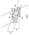
- one arranged in the rotating sleeve Recess partly due to the slope described above is limited, varies over the circumference of the rotating sleeve has large cross sections.
- a restoring force Presses the rotating sleeve in the direction of its starting position.
- This Restoring force can e.g. achieved by a coil spring become.
- the restoring force is adjustable, there is also one for this spring pneumatic spring whose pneumatic pressure is adjustable is.
- the coupling is advantageously used for tubular shaft instruments used.
- connection is made by restoring forces of at least a spring and / or by means of positive pins receive.
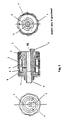
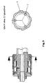
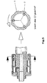
- a rotating sleeve 1 can be seen, which has a recess 13 on its inner circumference. This recess is shown enlarged in FIG. 4.
- a ball 7 which is in a axially movable ball sleeve 3 is arranged.
- the axially movable ball sleeve is held by a compression spring 5 pressed into their initial position.
- the restoring force of a Torsion spring 6 prevents the unwanted rotation of the Rotating sleeve 1.
- the clutch is through a stop plate 4 and Cover sleeve against penetration e.g. of dirt on the Protected shaft tube side.
Claims (19)
- Coupleur pour instruments à manche tubulaire pour la fixation relâchable d'une partie d'instrument (10) à un tube de manche (9), dans lequel la partie d'instrument (10) sur une surface extérieure (16) sur une extrémité (14), qui s'étend jusqu'au coupleur ou ledit tube de manche (9), est muni d'au moins un col (11), et dans lequel le coupleur est apte à être monté sur ledit tube de manche ou ladite parie d'instrument, comprenantune manche rotative (1) pour dégager le coupleur par rotation, qui est disposée autour d'un élément récepteur de la manche (2), dans lequelune manche de verrouillage (3) mobile in en sens axial, qui est défini par l'axe longitudinal (15) dudit tube de manche (9), qui est disposé entre ladite chemise rotative (1) et ledit élément récepteur de la manche (2) et qui reçoit au moins un élément de verrouillage (7), qui est mobile vers l'extérieur, etdans lequel le coupleur relie ladite partie d'instrument (10) audit tube de manche (9) par prise de verrouillage dudit élément ou desdits éléments de verrouillage (7) avec ledit col ou lesdits cols (11).
- Coupleur selon la revendication 1,
caractérisé en ce que ledit ou chaque col (11) a une configuration conique. - Coupleur selon la revendication 1 ou 2,
caractérisé en ce que ladite manche de verrouillage mobile (3) est une manche sphérique, pendant que ledit élément ou lesdits éléments de verrouillage (7) est/sont des sphères (7). - Coupleur selon une quelconque des revendications 1 à 3,
caractérisé en ce que quand ladite partie d'instrument (10) est insérée, ledit élément de verrouillage (7) est déplacé à force par une extrémité de ladite partie d'instrument (10) le long d'une pente (12). - Coupleur selon la revendication 4,
caractérisé en ce que ladite pente (12) a une configuration conique. - Coupleur selon la revendication 4 ou 5,
caractérisé en ce que l'angle (A), qui est défini par l'axe (15) et ladite pente (12) est plus large que l'angle (B) défini par ledit axe (15) et ledit col (11). - Coupleur selon une quelconque des revendications 1 à 6,
caractérisé en ce que ladite manche de verrouillage (3) est pressée par une force de remise en un sens vers sa position de départ. - Coupleur selon la revendication 7,
caractérisé en ce que la force de remise est créée par un ressort comme un ressort hélicoïdal, un ressort de torsion ou un ressort de compression (5). - Coupleur selon une quelconque des revendications 1 à 8,
caractérisé en ce qu'un évidement (13) disposé dans ladite chemise rotative (1), qui est défini en partie par ladite pente (12), présente des coupes transversales différentes le long de la périphérie de ladite chemise rotative. - Coupleur selon une quelconque des revendications 8 ou 9,
caractérisé en ce que quand ladite chemise rotative (1) est tournée en dehors de sa position de départ, ledit élément ou respectivement lesdits éléments de verrouillage (7) peuvent s'étendre plus loin dans ledit évidement (13), en étant dégageable dudit col (11) dans ladite poignée. - Coupleur selon une quelconque des revendications 8 à 10,
caractérisé en ce qu'une force de remise presse ladite chemise rotative (1) en un sens vers sa position de départ. - Coupleur selon la revendication 11,
caractérisé en ce que la force de remise est engendrée par un ressort en spirale. - Coupleur selon une quelconque des revendications 1 à 12,
caractérisé en ce que la prise de verrouillage relâchable d'au moins une goupille dans un trou empêche une rotation de ladite chemise rotative (1), quand ladite partie d'instrument (10) est raccordé au coupleur. - Procédé de raccorder une partie d'instrument à un tube de manche, par l'emploi d'un coupleur selon une quelconque des revendications 1 à 13,
caractérisé en ce quela partie d'instrument est poussée dans l'élément récepteur de la manche et entre en contact avec au moins un élément de verrouillage,sous un effet de poussée en continu sur la partie d'instrument, l'élément de verrouillage se déplace jusqu'à une position la plus loin, relativement à la position de départ,et sous un effet plus continu sur la partie d'instrument, l'élément de verrouillage retourne encore en sens vers la position de départ et dans ledit col (11) de ladite partie d'instrument (10). - Procédé selon la revendication 14,
caractérisé en ce que le découplage se fait par une rotation de ladite chemise rotative (1) et une traction simultanée sur ladite partie d'instrument (10). - Emploi d'un coupleur selon une quelconque des revendications 1 à 15 pour instruments à manche tubulaire aptes à être démonté ou pour instruments endoscopiques insérés dans une manche.
- Coupleur comprenantune manche de verrouillage (3) configurée comme manche sphérique, qui est disposée entre une chemise rotative (1) et un élément récepteur de la manche (2) et qui reçoit au moins une sphère (7) comme élément de verrouillage, ladite sphère ou respectivement lesdites sphères (7) étant mobiles à l'extérieur,une manche rotative (1) à dégager le coupleur par rotation, qui comprend un évidemment (13) le long de sa périphérie, qui est définie, au moins en partie, par une pente (12) et s'enfonce dans ladite chemise rotative sur des distances différentes, dans lequelladite manche de verrouillage (3) est capable de se déplacer en sens de l'axe longitudinal du coupleur et entre en contact avec ladite chemise rotative (1) au moins en partie, etdans lequel ladite sphère ou respectivement lesdites sphères (7) est/sont apte(s) à être entraíné, ensemble avec ladite manche de verrouillage (3), en sens de l'axe longitudinal du coupleur et de plus à un mouvement environ à un angle droit relativement à l'axe longitudinal du coupleur, à la déviation de la sphère respective (7) et l'étendue dudit évidement (13), qui est disposé environ à un angle droit relativement à l'axe longitudinal, étant limité par ladite pente (12).
- Coupleur selon la revendication 17,
caractérisé en ce qu'il sert à raccorder une partie d'instrument (10) ou un tube de manche (9), et en ce qu'à une extrémité de ladite partie d'instrument (10) ou respectivement dudit tube de manche (9), au moins un col (11) est formé pour la prise de ladite sphère ou respectivement desdites sphères (7) après le montage. - Coupleur selon la revendication 18,
caractérisé en ce que la connexion se fait par des forces de remise d'au moins deux ressorts ou moyennant des goupilles crabotées.
Applications Claiming Priority (3)
| Application Number | Priority Date | Filing Date | Title |
|---|---|---|---|
| DE19514098 | 1995-04-13 | ||
| DE19514098A DE19514098C2 (de) | 1995-04-13 | 1995-04-13 | Kupplung für Rohrschaftinstrumente |
| PCT/DE1996/000650 WO1996032068A1 (fr) | 1995-04-13 | 1996-04-15 | Accouplement pour instruments tubulaires |
Publications (2)
| Publication Number | Publication Date |
|---|---|
| EP0820256A1 EP0820256A1 (fr) | 1998-01-28 |
| EP0820256B1 true EP0820256B1 (fr) | 2002-07-24 |
Family
ID=7759685
Family Applications (1)
| Application Number | Title | Priority Date | Filing Date |
|---|---|---|---|
| EP96909046A Expired - Lifetime EP0820256B1 (fr) | 1995-04-13 | 1996-04-15 | Accouplement pour instruments tubulaires |
Country Status (4)
| Country | Link |
|---|---|
| US (1) | US6129392A (fr) |
| EP (1) | EP0820256B1 (fr) |
| DE (2) | DE19514098C2 (fr) |
| WO (1) | WO1996032068A1 (fr) |
Cited By (1)
| Publication number | Priority date | Publication date | Assignee | Title |
|---|---|---|---|---|
| DE102022125154A1 (de) | 2022-09-29 | 2024-04-04 | Karl Storz Se & Co. Kg | Chirurgisches Instrument mit Kopplungsvorrichtung |
Families Citing this family (17)
| Publication number | Priority date | Publication date | Assignee | Title |
|---|---|---|---|---|
| US5893874A (en) * | 1997-02-07 | 1999-04-13 | Smith & Nephew, Inc. | Surgical instrument |
| DE19930426C2 (de) | 1999-07-01 | 2001-05-03 | Storz Karl Gmbh & Co Kg | Medizinisches, insbesondere chirurgisches Instrument |
| US7296804B2 (en) * | 2000-06-24 | 2007-11-20 | Precimed S.A. | Hand-held instrument holder for surgical use |
| US7221836B2 (en) * | 2003-08-12 | 2007-05-22 | Karl Storz Endovision, Inc. | Light diffusing fiberoptic coupling |
| DE10357103A1 (de) | 2003-12-06 | 2005-07-07 | Richard Wolf Gmbh | Medizinisches Instrument |
| US7678117B2 (en) | 2004-06-07 | 2010-03-16 | Novare Surgical Systems, Inc. | Articulating mechanism with flex-hinged links |
| US7828808B2 (en) | 2004-06-07 | 2010-11-09 | Novare Surgical Systems, Inc. | Link systems and articulation mechanisms for remote manipulation of surgical or diagnostic tools |
| DE202005016761U1 (de) * | 2005-10-26 | 2006-11-30 | Joimax Gmbh | Facettengelenkfräser |
| DE102007007904B3 (de) * | 2007-02-14 | 2008-04-30 | Paul Peschke Gmbh | Kupplung für ein Rohrschaftinstrument |
| DE102007032202B4 (de) * | 2007-07-11 | 2010-11-25 | Schölly Fiberoptic GmbH | Endoskop |
| US9444197B2 (en) * | 2012-03-19 | 2016-09-13 | Holland Electronics, Llc | Shielded and multishielded coaxial connectors |
| WO2014003848A1 (fr) * | 2012-06-29 | 2014-01-03 | Gyrus Acmi, Inc. | Mécanisme de retenue de lame pour instrument chirurgical |
| DE202013000025U1 (de) * | 2013-01-07 | 2013-01-29 | Schölly Fiberoptic GmbH | Endoskop |
| CN104958093B (zh) * | 2013-09-30 | 2017-10-10 | 常州市新能源吻合器总厂有限公司 | 腹腔镜手术用穿刺器 |
| US11090097B2 (en) | 2015-03-17 | 2021-08-17 | Covidien Lp | Connecting end effectors to surgical devices |
| CN112057119B (zh) * | 2020-09-11 | 2021-05-18 | 杭州键嘉机器人有限公司 | 末端执行器 |
| CN217447937U (zh) * | 2020-11-04 | 2022-09-20 | 安速康医疗(苏州)有限公司 | 超声手术刀 |
Family Cites Families (11)
| Publication number | Priority date | Publication date | Assignee | Title |
|---|---|---|---|---|
| US1868587A (en) * | 1928-12-26 | 1932-07-26 | Richards Alonzo | Means for connecting an implement to a motor |
| US3032359A (en) * | 1958-05-05 | 1962-05-01 | Crawford Fitting Co | Quick connect coupling |
| US3083042A (en) * | 1958-08-25 | 1963-03-26 | Lear Siegler Inc | Quick connect coupling |
| US3351359A (en) * | 1964-12-23 | 1967-11-07 | Electrolux Corp | Adjustable length wand |
| US4382790A (en) * | 1979-09-19 | 1983-05-10 | Kaltenbach & Voight Gmbh & Co. | Dental handpiece |
| DE3100512C2 (de) * | 1981-01-10 | 1984-07-12 | Gustav Neuhäuser oHG Präzisionswerkzeugfabrik, 7130 Mühlacker | Schnellwechselfutter |
| US4444223A (en) * | 1981-05-26 | 1984-04-24 | Imperial Clevite Inc. | Quick disconnect coupling |
| US4403959A (en) * | 1981-07-31 | 1983-09-13 | Kabushiki Kaisha Yoshida Seisakusho | Coupling device for a dental instrument |
| US4577875A (en) * | 1982-10-29 | 1986-03-25 | Miyakawa Industry Co., Ltd. | Exchange chuck for a tool |
| DE3934610A1 (de) * | 1989-10-17 | 1991-04-25 | Aesculap Ag | Schnellkupplung fuer chirurgische instrumente |
| DE4311161A1 (de) * | 1993-04-05 | 1994-10-06 | Kress Elektrik Gmbh & Co | Schnellspannvorrichtung für Stichsägeblätter |
-
1995
- 1995-04-13 DE DE19514098A patent/DE19514098C2/de not_active Expired - Fee Related
-
1996
- 1996-04-15 DE DE59609481T patent/DE59609481D1/de not_active Expired - Lifetime
- 1996-04-15 EP EP96909046A patent/EP0820256B1/fr not_active Expired - Lifetime
- 1996-04-15 US US08/945,006 patent/US6129392A/en not_active Expired - Lifetime
- 1996-04-15 WO PCT/DE1996/000650 patent/WO1996032068A1/fr active IP Right Grant
Cited By (1)
| Publication number | Priority date | Publication date | Assignee | Title |
|---|---|---|---|---|
| DE102022125154A1 (de) | 2022-09-29 | 2024-04-04 | Karl Storz Se & Co. Kg | Chirurgisches Instrument mit Kopplungsvorrichtung |
Also Published As
| Publication number | Publication date |
|---|---|
| WO1996032068A1 (fr) | 1996-10-17 |
| DE59609481D1 (de) | 2002-08-29 |
| EP0820256A1 (fr) | 1998-01-28 |
| US6129392A (en) | 2000-10-10 |
| DE19514098C2 (de) | 2001-01-25 |
| DE19514098A1 (de) | 1996-10-17 |
Similar Documents
| Publication | Publication Date | Title |
|---|---|---|
| EP0820256B1 (fr) | Accouplement pour instruments tubulaires | |
| EP1537829B1 (fr) | Dispositif médical comprenant insert et moyen pour le blocage de la manche | |
| DE19707373C1 (de) | Bajonettkupplung zum lösbaren Verbinden zweier Rohrschaftinstrumente oder -instrumententeile | |
| DE10358554B4 (de) | Chirurgisches Instrument zum Sezieren von Knochen oder anderem Gewebe mit Teleskopaufsatz | |
| DE102010000627B4 (de) | Punktionsnadelvorrichtung für ein Ultraschallendoskop | |
| DE60225422T2 (de) | Chirurgisches rotationsschneidwerkzeug mit schnelllösekupplung | |
| EP3076891B1 (fr) | Dispositif d'entraînement pour un instrument endoscopique à tige | |
| EP1523932B1 (fr) | Endoscope | |
| EP2612609B2 (fr) | Instrument médical | |
| EP2892441B1 (fr) | Instrument chirurgical transmettant un couple et comprenant un outil correspondant | |
| DE102012108267A1 (de) | Chirurgisches, Drehmoment übertragendes Instrument einschließlich zugehöriges Werkzeug | |
| EP2892442B1 (fr) | Instrument chirurgical transmettant un couple et comprenant un outil correspondant | |
| DE202009017470U1 (de) | Chirurgisches Instrument zur lösbaren Verbindung eines Handstückes mit einem chirurgischen Werkzeug | |
| EP1261285A1 (fr) | Dispositif d'accouplement pour parties constitutives d'instruments | |
| DE4103663A1 (de) | Chirurgisches handstueck | |
| EP2401953A1 (fr) | Dispositif de couplage pour une connexion amovible entre l'oculaire d'un endoscope et une caméra | |
| DE4401663A1 (de) | Werkzeughalter | |
| AT412322B (de) | Schnellkupplung zur verbindung von geräten eines medizinischen oder chirurgischen handstücksystems mit einem versorgungsschlauch | |
| EP2732778B1 (fr) | Instrument médical | |
| EP2892447B1 (fr) | Instrument chirurgical transmettant un couple et comprenant un outil correspondant | |
| EP3574864A1 (fr) | Dispositif et procédé d'accouplement auto-bloquant | |
| EP3135183B1 (fr) | Instrument medical micro-invasif | |
| DE102022119979A1 (de) | Medizinisches Motorhandstück für 2-in-1-Bedienung sowie medizinisches Handinstrument mit 2-in-1-Bedienung | |
| EP2656801B1 (fr) | Dispositif de fixation d'outil pour une pièce à main médicale, notamment dentaire ou chirurgicale | |
| DE202021101150U1 (de) | Medizinisches Instrument und medizinisches Endoskop mit einem solchen Instrument |
Legal Events
| Date | Code | Title | Description |
|---|---|---|---|
| PUAI | Public reference made under article 153(3) epc to a published international application that has entered the european phase |
Free format text: ORIGINAL CODE: 0009012 |
|
| 17P | Request for examination filed |
Effective date: 19971014 |
|
| AK | Designated contracting states |
Kind code of ref document: A1 Designated state(s): AT BE CH DE DK ES FI FR GB GR IE IT LI LU MC NL PT SE Kind code of ref document: A1 Designated state(s): DE FR GB IT |
|
| RAP1 | Party data changed (applicant data changed or rights of an application transferred) |
Owner name: KARL STORZ GMBH & CO. KG |
|
| 17Q | First examination report despatched |
Effective date: 20000330 |
|
| GRAG | Despatch of communication of intention to grant |
Free format text: ORIGINAL CODE: EPIDOS AGRA |
|
| GRAG | Despatch of communication of intention to grant |
Free format text: ORIGINAL CODE: EPIDOS AGRA |
|
| GRAH | Despatch of communication of intention to grant a patent |
Free format text: ORIGINAL CODE: EPIDOS IGRA |
|
| GRAH | Despatch of communication of intention to grant a patent |
Free format text: ORIGINAL CODE: EPIDOS IGRA |
|
| GRAA | (expected) grant |
Free format text: ORIGINAL CODE: 0009210 |
|
| RBV | Designated contracting states (corrected) |
Designated state(s): DE FR GB IT |
|
| AK | Designated contracting states |
Kind code of ref document: B1 Designated state(s): DE FR GB IT |
|
| REG | Reference to a national code |
Ref country code: GB Ref legal event code: FG4D Free format text: NOT ENGLISH |
|
| GBT | Gb: translation of ep patent filed (gb section 77(6)(a)/1977) |
Effective date: 20020724 |
|
| REF | Corresponds to: |
Ref document number: 59609481 Country of ref document: DE Date of ref document: 20020829 |
|
| ET | Fr: translation filed | ||
| PLBE | No opposition filed within time limit |
Free format text: ORIGINAL CODE: 0009261 |
|
| STAA | Information on the status of an ep patent application or granted ep patent |
Free format text: STATUS: NO OPPOSITION FILED WITHIN TIME LIMIT |
|
| 26N | No opposition filed |
Effective date: 20030425 |
|
| REG | Reference to a national code |
Ref country code: FR Ref legal event code: PLFP Year of fee payment: 20 |
|
| PGFP | Annual fee paid to national office [announced via postgrant information from national office to epo] |
Ref country code: FR Payment date: 20150319 Year of fee payment: 20 Ref country code: GB Payment date: 20150324 Year of fee payment: 20 |
|
| PGFP | Annual fee paid to national office [announced via postgrant information from national office to epo] |
Ref country code: DE Payment date: 20150319 Year of fee payment: 20 |
|
| PGFP | Annual fee paid to national office [announced via postgrant information from national office to epo] |
Ref country code: IT Payment date: 20150325 Year of fee payment: 20 |
|
| REG | Reference to a national code |
Ref country code: DE Ref legal event code: R071 Ref document number: 59609481 Country of ref document: DE |
|
| REG | Reference to a national code |
Ref country code: GB Ref legal event code: PE20 Expiry date: 20160414 |
|
| PG25 | Lapsed in a contracting state [announced via postgrant information from national office to epo] |
Ref country code: GB Free format text: LAPSE BECAUSE OF EXPIRATION OF PROTECTION Effective date: 20160414 |