EP0820209A2 - Dispositif de transfert de données ayant une fonction de commande de retransmission - Google Patents
Dispositif de transfert de données ayant une fonction de commande de retransmission Download PDFInfo
- Publication number
- EP0820209A2 EP0820209A2 EP97112138A EP97112138A EP0820209A2 EP 0820209 A2 EP0820209 A2 EP 0820209A2 EP 97112138 A EP97112138 A EP 97112138A EP 97112138 A EP97112138 A EP 97112138A EP 0820209 A2 EP0820209 A2 EP 0820209A2
- Authority
- EP
- European Patent Office
- Prior art keywords
- parameter
- data
- data transfer
- protocol
- packets
- Prior art date
- Legal status (The legal status is an assumption and is not a legal conclusion. Google has not performed a legal analysis and makes no representation as to the accuracy of the status listed.)
- Withdrawn
Links
Images


Classifications
-
- H—ELECTRICITY
- H04—ELECTRIC COMMUNICATION TECHNIQUE
- H04Q—SELECTING
- H04Q11/00—Selecting arrangements for multiplex systems
- H04Q11/04—Selecting arrangements for multiplex systems for time-division multiplexing
- H04Q11/0428—Integrated services digital network, i.e. systems for transmission of different types of digitised signals, e.g. speech, data, telecentral, television signals
- H04Q11/0478—Provisions for broadband connections
-
- H—ELECTRICITY
- H04—ELECTRIC COMMUNICATION TECHNIQUE
- H04L—TRANSMISSION OF DIGITAL INFORMATION, e.g. TELEGRAPHIC COMMUNICATION
- H04L12/00—Data switching networks
- H04L12/54—Store-and-forward switching systems
- H04L12/56—Packet switching systems
- H04L12/5601—Transfer mode dependent, e.g. ATM
- H04L2012/5614—User Network Interface
- H04L2012/5616—Terminal equipment, e.g. codecs, synch.
-
- H—ELECTRICITY
- H04—ELECTRIC COMMUNICATION TECHNIQUE
- H04L—TRANSMISSION OF DIGITAL INFORMATION, e.g. TELEGRAPHIC COMMUNICATION
- H04L12/00—Data switching networks
- H04L12/54—Store-and-forward switching systems
- H04L12/56—Packet switching systems
- H04L12/5601—Transfer mode dependent, e.g. ATM
- H04L2012/5629—Admission control
- H04L2012/563—Signalling, e.g. protocols, reference model
-
- H—ELECTRICITY
- H04—ELECTRIC COMMUNICATION TECHNIQUE
- H04L—TRANSMISSION OF DIGITAL INFORMATION, e.g. TELEGRAPHIC COMMUNICATION
- H04L12/00—Data switching networks
- H04L12/54—Store-and-forward switching systems
- H04L12/56—Packet switching systems
- H04L12/5601—Transfer mode dependent, e.g. ATM
- H04L2012/5629—Admission control
- H04L2012/5631—Resource management and allocation
- H04L2012/5636—Monitoring or policing, e.g. compliance with allocated rate, corrective actions
Definitions
- the present invention relates to a data transfer device, and more particularly, to a data transfer device on which a retransmission control protocol is packaged in order to ensure the loss of a data packet due to an error on a line in establishing communication through an ATM (Asynchronous Transfer Mode) communication network.
- ATM Asynchronous Transfer Mode
- a data packet is transferred upon being partitioned into cells having a fixed length of 53 bytes.
- the cells are discarded, so that data is lost.
- a method to package a protocol having a retransmission control function on ATM has been conventionally employed.
- the protocol having the retransmission control function a system for packaging TCP/IP has been generally employed.
- sufficient throughput cannot be obtained (see an article entitled "A Measurement of TCP Throughput over High-Speed and Long-Delay Network" by Ito et al. in Technical Report of Ieice. IN95-9 issued by The Institute of Electronics, Information and Communication Engineers).
- ITU-TS International Telecommunication Union-Telecommunication Sector
- SSCOP Service Specific Connection Oriented Protocol
- the SSCOP employs a selective retransmission system. Even when retransmission is produced, therefore, sufficient throughput can be maintained. Further, the arrival delay of a data packet for the retransmission can be reduced.
- the definition of the SSCOP in ITU - T Recommendation is unsuitable for transfer of a large amount of data because it premises the use for signaling.
- a sequence number is added for each data packet whose transfer is required, to produce a protocol data unit called SD (hereinafter referred to as PDU), and the PDU is transmitted to a device which is a destination of connection.
- SD protocol data unit
- a data link is first set.
- the data link is set by transferring PDU called BGN to the device which is a destination of connection.
- a device on the receiving side which received the BGN produces PDU called BGAK and sends out the PDU, to accept the setting of the data link.
- the first value (hereinafter referred to as NMR) of the sequence numbers of SDs which cannot be received by the device on the receiving side is added to the BGAK.
- the NMR takes a value representing SD(8), i.e., 8.
- a device on the transmission side can send out SDs in a range in which the number of the SDs does not exceed the NMR. Consequently, the NMR is also called a credit value.
- the device on the transmission side produces SD upon acceptance of a data transfer request, and sends out the SD to the line.
- SD(0) shown in Fig. 8 is sent out.
- a data region for the SD sent out is held by the device on the transmission side.
- SD(1) to SD(5) are sent out.
- the device on the transmission side produces PDU called POLL (a delivery confirmation packet), and sends out the PDU.
- the sequence number (hereinafter referred to as NS) of SD to be subsequently transmitted, that is, 6 in this case is added to the POLL.
- the device on the receiving side produces PDU called STAT after confirming whether or not there is no omission in data to be received upon acceptance of the POLL.
- the sequence number of the SD which cannot be received, the sequence number (hereinafter referred to as NR) of SD succeeding the SDs continuously received and the NMR are added to the STAT.
- the difference between the NMR and the NR is a window size on the transmission side (a value representing the number of SDs which may be sent).
- the device on the transmission side retransmits the SD which cannot be received by the device on the receiving side upon receipt of the STAT, while releasing a data region for the SDs continuously received by the device on the receiving side. In this case, a data region for SD(0) to SD(5) is released.
- the followings are timings at which POLLs are sent out from the device on the transmission side.
- the first timing is timing after sending out a predetermined number of SDs.
- the number is defined as a protocol parameter, and is referred to as MaxPD.
- the second timing is the time when a time-out of a timer for monitoring a transmission interval of the POLLs occurs. This timer period is referred to as Timer_POLL, and a time-out value of the timer period is defined as a protocol parameter.
- the POLL is produced, and is sent out.
- a counter for counting the number of SDs continuously transferred which is to be compared with the MaxPD is cleared, and the Timer_POLL is also restarted.
- Fig. 8 illustrates an example in a case where the MaxPD is six.
- the POLL is immediately sent out. If the SDs are sparsely transmitted, the POLL is not sent out until the time corresponding to the timer value of the Timer_POLL has elapsed.
- the transmission of the POLL is delayed, the receiving of the STAT is also delayed. Therefore, the updating of the window size and the releasing of the data region held by the device on the transmission side are delayed.
- the data transfer performance is changed depending on the transfer interval of data packets and the values of the protocol parameters.
- the values of the protocol parameters are fixedly determined for signaling.
- the procedure for retransmission control is carried out on the ATM network, and a high performance can be obtained.
- the protocol parameters are fixedly set, thereby various patterns for the data transfer cannot be coped with.
- it is necessary to consider construction suitable for the data transfer Specifically, such construction that various protocol parameters required for SSCOP processing can be set to values suitable for the transfer of the data packets is necessary.
- An object of the present invention is to provide a data transfer device capable of always efficiently transferring data irrespective of the type of data when the data is transferred using protocol processing including the procedure for selective retransmission such as SSCOP.
- the present invention has the following characteristics.
- a first aspect of the present invention is directed to a data transfer device for establishing data communication through an ATM network, comprising:
- the contents of setting of the protocol parameters are changed depending on the communication state, thereby the most suitable parameters can be always set in conformity to the change in a data transfer pattern. Consequently, it is possible to also exhibit a sufficient data transfer performance with respect to the transfer of data high in real time properties such as video data.
- a second aspect is characterized in that in the first aspect,
- the parameter MaxPD for defining the transmission interval of the delivery confirmation packets out of the plurality of protocol parameters stored in the parameter table is changed, thereby the protocol parameter can be set to such a value that the delivery confirmation packet after the transmission of data packets can be sent out at suitable timing.
- a third aspect is characterized in that in the second aspect,
- the number of data packets transferred at one time on the logical connection is set as the value of MaxPD, thereby it is possible to send out the delivery confirmation packets immediately after the data packets continuously sent out, and quickly confirm the delivery of the data.
- the data region held on the transmission side can be quickly released, and can be efficiently used.
- a window size is updated immediately after the data transfer, thereby it is possible to avoid situations where the window size is not updated by the impossibility of the confirmation of the delivery.
- a fourth aspect is characterized by further comprising, in the second aspect,
- a fifth aspect is characterized in that in the fourth aspect,
- the value of MaxPD is dynamically changed depending on the transfer interval of the data packets, thereby the delivery confirmation packets are sent out at an interval always shorter than an interval at which a time-out of the timer period Timer_POLL occurs.
- a sixth aspect is characterized by further comprising, in the second aspect,
- a seventh aspect is characterized in that in the sixth aspect,
- the window size is calculated on the basis of the NMR and the NR reported from the receiving side, and a value smaller than the calculated window size is set as the value of MaxPD. Even when the window size given from a device on the receiving side is small, the data can be transferred without stopping the transmission of the data packets due to the window size.
- An eighth aspect is characterized in that in the first aspect,
- a ninth aspect is characterized in that in the eighth aspect,
- the protocol parameter is managed for each logical channel.
- the most suitable data transfer can be made for each logical channel.
- Fig. 1 is a block diagram showing the construction of a data transfer device according to a first embodiment of the present invention.
- a data transfer device 16 according to the present embodiment comprises a protocol processing portion 11, a parameter managing portion 12, a connection setting portion 13, a data transfer application 14, and a communication control portion 15.
- the protocol processing portion 11 performs SSCOP processing having a retransmission control function while referring to protocol parameters stored in the parameter managing portion 12.
- the parameter managing portion 12 includes a parameter changing portion 121, and a parameter table 122, as shown in Fig. 2.
- the protocol parameters required in performing the SSCOP processing in the protocol processing portion 11 are stored in the parameter table 122.
- the parameter changing portion 121 changes the setting of the protocol parameters in the parameter table, as required.
- the connection setting portion 13 sets a logical channel between the data transfer device and a data transfer device which is a destination of communication through an ATM network 17, to allow data transfer.
- the data transfer application 14 instructs the connection setting portion 13 to set a logical channel between the data transfer device and a device which is a destination of data transfer, then assembles data to be transferred into packets, and requires the transmission of the packet data of the protocol processing portion 11.
- the communication control portion 15 performs processing for sending out to the ATM network 17 control data for setting the logical channel given by the connection setting portion 13 or the packet data given by the protocol processing portion 11.
- Fig. 3 illustrates the construction of the parameter table 122 shown in Fig. 2.
- the parameter table 122 stores the protocol parameters required in SSCOP defined in ITU-T Recommendation, including MaxPD.
- Fig. 4 is a sequence chart showing, in a communication system using the data transfer device shown in Fig. 1, a sequence in performing data transfer between data transfer devices through the ATM network 17.
- the data transfer application 14 collectively requires the transmission of a plurality of SDs.
- cases such as a case where the size of data handled by the data transfer application 14 is large, so that the data is sent upon being partitioned into some packets at the time of transfer are considered.
- the number of partitions is the number of data packets whose transfer is required at one time from the data transfer application 14.
- the data transfer application 14 previously gives the number of partitions to the parameter changing portion 121.
- the parameter changing portion 121 sets the given number of partitions in the parameter table 122 as MaxPD in Fig. 3. In the present embodiment, the number of partitions is taken as four as one example. Default values shall be set with respect to the other parameters in Fig. 3.
- the data transfer application 14 then connects a logical connection between the data transfer device and a device to which the data packets are to be transmitted. Therefore, the data transfer application 14 requires the setting of a connection in which an address of a destination of connection is specified of the connection setting portion 13.
- the connection setting portion 13 brings the data transfer device 16 into a state where communication with a destination of connection can be started by performing prescribed connection setting processing.
- SVC Switchched Virtual Channel
- the connection setting portion 13 performs protocol processing between the data transfer device and an exchange using a signaling protocol, to set assigned logical channel ID and QoS (Quality of Service) in the communication control portion 15.
- the data transfer application 14 When the setting of the logical connection by the connection setting portion 13 is completed, the data transfer application 14 requires the setting of a data link with respect to a device which is a destination of connection.
- the data link is set in the conventional procedure in the protocol processing portion 11.
- the detailed procedure for data link processing is not the prime object of the present invention and hence, the description thereof is omitted.
- the data packets are transferred.
- the data transfer application 14 produces four packets at one time, and issues a transfer request to the protocol processing portion 11 for each data packet.
- SD is produced from the required packet, and is sent out to the ATM network 17 through the communication control portion 15.
- Supposing the first SD is taken as SD(0), four PDUs, that is, SD(0), SD(1), SD(2) and SD(3) are sent out, as shown in Fig. 4.
- the device on the transmission side releases a data region for SD(0) to SD(3) upon receiving the STAT.
- the number of data packets whose transfer is required at one time by the data transfer application 14 is set as the value of MaxPD, so that the POLL can be sent out immediately after the SDs continuously sent out. Therefore, the delivery of the data can be quickly confirmed, and the data region held by the device on the transmission side can be quickly released. As a result, the data region can be efficiently used. Further, the window size is updated immediately after the data transfer, thereby it is possible to avoid situations where the window size is not updated by the impossibility of the confirmation of the delivery.
- Fig. 5 is a block diagram showing the construction of a data transfer device according to a second embodiment of the present invention.
- a data transfer device 43 in the present embodiment comprises a protocol processing portion 11, a parameter managing portion 12, a connection setting portion 13, a data transfer application 14, a communication control portion 15, a data transfer monitoring portion 41, and a parameter calculating portion 42.
- the data transfer monitoring portion 41 monitors a transfer interval of data packets transmitted through the communication control portion 15.
- the parameter calculating portion 42 calculates the value of MaxPD on the basis of the transfer interval of the data packets which is monitored by the data transfer monitoring portion 41 and protocol parameters managed by the parameter managing portion 12.
- the protocol processing portion 11, the parameter managing portion 12, the connection setting portion 13, the data transfer application 14, and the communication control portion 15 are constructed similarly to corresponding ones shown in Fig. 1.
- MaxPD shown in Fig. 3 is set to a sufficiently small value in order that the transmission of SDs is not stopped due to a window size.
- the default value of MaxPD is taken as 1.
- the data transfer application 14 connects a logical connection and sets a data link using the same procedure as that in the first embodiment, refers to the default values of the protocol parameters managed by the parameter managing portion 12, and transfers data.
- the data transfer monitoring portion 41 monitors SDs given to the communication control portion 15 from the protocol processing portion 11, and calculates the average transfer interval of the SDs.
- the parameter calculating portion 42 calculates the number of SDs transferred within a timer period Timer_POLL shown in Fig. 3 managed by the parameter managing portion 12 on the basis of the average transfer interval calculated by the data transfer monitoring portion 41. When the average transfer interval is taken as 10 msec, and a timer value of the Timer_POLL is taken as 400 msec, for example, the number of SDs transferred within the timer period Timer_POLL is 40.
- the parameter calculating portion 42 outputs a value smaller than 40, for example, 20 (a value which is one-half of 40) as MaxPD to the parameter managing portion 12.
- the parameter changing portion 121 in the parameter managing portion 12 rewrites the value of MaxPD in the parameter table 122 shown in Fig. 3 from 1 to 20.
- the average transfer interval of SDs is monitored in the data transfer monitoring portion 41, the maximum transfer interval in a unit time may be monitored, so that the number of SDs transferred within the timer period Timer_POLL can be also calculated by the parameter calculating portion 42 on the basis of the maximum transfer interval.
- the parameter calculating portion 42 the value which is one-half of the number of SDs transferred within the timer period Timer_POLL is taken as MaxPD, the other value can be used, provided that it is not more than the number of SDs transferred within the timer period Timer_POLL.
- the value of MaxPD is dynamically changed depending on the transfer interval of the SDs, the POLLs are sent out at an interval which is always shorter than an interval at which a time-out of the Timer_POLL occurs. Specifically, it is possible to select and set the best protocol parameters in a case where the efficiency of the data transfer is not reduced by monitoring the actual situations where the data is transmitted.
- Fig. 6 is a block diagram showing the construction of a data transfer device according to a third embodiment of the present invention.
- a data transfer device 52 in the present embodiment comprises a protocol processing portion 11, a parameter managing portion 12, a connection setting portion 13, a data transfer application 14, a communication control portion 15, and a parameter calculating portion 51.
- the parameter calculating portion 51 calculates the value of MaxPD on the basis of the value of NR and the value of NMR which are received by the protocol processing portion 11.
- the protocol processing portion 11, the parameter managing portion 12, the connection setting portion 13, the data transfer application 14, and the communication control portion 15 are constructed similarly to corresponding ones shown in Fig. 1.
- the data transfer application 14 connects a logical connection and sets a data link using the same procedure as that in the first embodiment.
- the protocol processing portion 11 reports the value of NMR received at this time to the parameter calculating portion 51.
- the parameter calculating portion 51 outputs a value smaller than eight, for example, four (a value which is one-half of eight) as MaxPD to the parameter managing portion 12.
- the parameter changing portion 121 in the parameter managing portion 12 changes the value of MaxPD in the parameter table 122 shown in Fig. 3 to four. Thereafter, data transfer is made using the same procedure as that in the first embodiment.
- the protocol processing portion 11 reports to the parameter calculating portion 51 the NR and the NMR reported from a device on the receiving side at the time of receiving STAT.
- the parameter calculating portion 51 calculates eight which is the difference between them as a window size, and outputs a value which is smaller than eight, for example, four (a value which is one-half of eight) as MaxPD to the parameter managing portion 12.
- the parameter managing portion 12 sets four in the MaxPD shown in Fig. 3.
- the protocol processing portion 11 hereinafter makes the data transfer while referring to the value of MaxPD.
- the parameter calculating portion 51 takes a value which is one-hart of the window size as MaxPD, the other values can be used, provided that it is not more than the window size.
- the window size is calculated on the basis of the NR and the NMR reported from the device on the receiving side, and a value smaller than the calculated window size is set as MaxPD. Even when the window size given from the device on the receiving side is small, therefore, the data transfer can be made without stopping the transmission of SDs due to the window size.
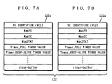
- Fig. 7 illustrates a parameter table used in the fourth embodiment. Protocol parameters for a first logical connection VC1 and protocol parameters for a second logical connection VC2 are respectively stored in a first parameter table 122a shown in Fig. 7 (a) and a second parameter table 122b shown in Fig. 7 (b).
- the fourth embodiment consider a case where a plurality of logical connections are set, and different data are transferred with the respective logical connections.
- the two logical connections are taken as first and second logical connections VC1 and VC2, and a destination of connection of the first logical connection VC1 and a destination of connection of the second logical connection VC2 are respectively taken as a first device and a second device.
- a data transfer application 14 gives the number of data packets whose transfer is required at one time to a parameter managing portion 12 for each logical channel, as in the first embodiment.
- a parameter changing portion 121 in the parameter managing portion 12 previously sets the number of data packets transferred at one time by the first logical connection VC1 in MaxPD in the first parameter table 122a, and previously sets the number of data packets transferred at one time by the second logical connection VC2 in MaxPD in the second parameter table 122b.
- Defaults values shall be set with respect to the other parameters shown in Fig. 7.
- the data transfer application 14 then requires setting of connections in which addresses of destinations of connection of the two logical connections VC1 and VC2 are specified of a connection setting portion 13 in order to connect the logical connections.
- the data transfer application 14 sets on the first logical connection VC1 a data link between the data transfer device and the first device. Similarly, the data transfer application 14 sets on the second logical connection VC2 a data link between the data transfer device and the second device. When the setting of the respective data links is completed, the data transfer application 14 starts the data transfer.
- protocol processing is separately performed for each logical connection. Consequently, different sequence numbers are assigned to the data packets for each logical connection.
- a protocol processing portion 11 produces SD to which a sequence number for the first device is added upon acceptance of a data transmission request addressed to the first device from the data transfer application 14, and transmits the SD to the first device.
- the protocol processing portion 11 increments a count value of a counter for counting the number of continuously transferred SDs in the first logical connection VC1 (provided inside the protocol processing portion 11) by one, compares the count value with the value of MaxPD set in the first parameter table 122a, and sends out POLL if the count value is not less than the value of MaxPD.
- the protocol processing portion 11 then produces SD to which a sequence number for the second device is added upon acceptance of a data request addressed to the second device from the data transfer application 14, and transmits the SD to the second device.
- the protocol processing portion 11 increments a count value of a counter for counting the number of continuously transferred SDs in the second logical connection VC2 (provided inside the protocol processing portion 11) by one, compares the count value with the value of MaxPD set in the second parameter table 122b, and sends out POLL if the count value is not less than the value of MaxPD.
- the number of logical channels to be multiplexed is taken as 2, three or more logical channels can be multiplexed by managing protocol parameters corresponding to the number of logical channels to be multiplexed by the parameter managing portion 12.
- the number of data packets transferred at one time is previously set as the value of MaxPD
- the protocol parameters are separately managed for each of the logical channels, thereby the data transfer can be made for each logical channel in the most suitable state.
Applications Claiming Priority (3)
| Application Number | Priority Date | Filing Date | Title |
|---|---|---|---|
| JP18716396 | 1996-07-17 | ||
| JP18716396A JPH1032584A (ja) | 1996-07-17 | 1996-07-17 | 再送制御機能を有するデータ転送装置 |
| JP187163/96 | 1996-07-17 |
Publications (2)
| Publication Number | Publication Date |
|---|---|
| EP0820209A2 true EP0820209A2 (fr) | 1998-01-21 |
| EP0820209A3 EP0820209A3 (fr) | 1999-12-22 |
Family
ID=16201230
Family Applications (1)
| Application Number | Title | Priority Date | Filing Date |
|---|---|---|---|
| EP97112138A Withdrawn EP0820209A3 (fr) | 1996-07-17 | 1997-07-16 | Dispositif de transfert de données ayant une fonction de commande de retransmission |
Country Status (3)
| Country | Link |
|---|---|
| US (1) | US6181700B1 (fr) |
| EP (1) | EP0820209A3 (fr) |
| JP (1) | JPH1032584A (fr) |
Cited By (2)
| Publication number | Priority date | Publication date | Assignee | Title |
|---|---|---|---|---|
| WO1999059299A1 (fr) * | 1998-05-08 | 1999-11-18 | Siemens Aktiengesellschaft | Procede de regulation du flux de donnees dans un reseau de communication |
| WO2001049062A1 (fr) * | 1999-12-23 | 2001-07-05 | Nokia Corporation | Distribution de minuteurs et de parametres a la sous-couche de convergence specifique d'un service (sscs) de la couche d'adaptation mta de signalisation (saal) sur l'interface de noeud de reseau (nni) et sur l'interface usager/reseau (uni) |
Families Citing this family (11)
| Publication number | Priority date | Publication date | Assignee | Title |
|---|---|---|---|---|
| JP3315926B2 (ja) * | 1998-05-25 | 2002-08-19 | ケイディーディーアイ株式会社 | Tcp通信高速化装置 |
| US6961749B1 (en) | 1999-08-25 | 2005-11-01 | Network Appliance, Inc. | Scalable file server with highly available pairs |
| US6883120B1 (en) * | 1999-12-03 | 2005-04-19 | Network Appliance, Inc. | Computer assisted automatic error detection and diagnosis of file servers |
| US6606321B1 (en) * | 1999-12-29 | 2003-08-12 | 3Com Corporation | Method of establishing MPOA shortcut virtual channel connections |
| CA2393502A1 (fr) * | 2002-07-15 | 2004-01-15 | Mark J. Frazer | Systeme et methode de transport fiable dans un reseau informatique |
| US20060075203A1 (en) * | 2002-12-12 | 2006-04-06 | Koninklijke Philips Electronics N.V. | Configurable memory partitioning in hardware |
| WO2007066588A1 (fr) | 2005-12-09 | 2007-06-14 | Nec Corporation | Système de communication de réseau local sans fil |
| EP1863212A2 (fr) | 2006-06-01 | 2007-12-05 | Innovative Sonic Limited | Procédé pour fenêtre de réception double et appareil pour requête de retransmission automatique |
| US7895298B1 (en) | 2008-03-14 | 2011-02-22 | Duane Allen Murray | Publicly accessible delivery confirmation system for virtual digital download items |
| JP6404129B2 (ja) * | 2015-01-19 | 2018-10-10 | 富士通株式会社 | 通信装置、通信制御プログラム、および通信制御方法 |
| US11711167B2 (en) * | 2018-11-01 | 2023-07-25 | Nokia Technologies Oy | Apparatus, method and computer program |
Citations (2)
| Publication number | Priority date | Publication date | Assignee | Title |
|---|---|---|---|---|
| EP0355797A2 (fr) * | 1988-08-26 | 1990-02-28 | Hitachi, Ltd. | Appareil de signalisation pour utilisation dans un système de commutation ATM |
| US5483526A (en) * | 1994-07-20 | 1996-01-09 | Digital Equipment Corporation | Resynchronization method and apparatus for local memory buffers management for an ATM adapter implementing credit based flow control |
Family Cites Families (4)
| Publication number | Priority date | Publication date | Assignee | Title |
|---|---|---|---|---|
| JP3136183B2 (ja) * | 1992-01-20 | 2001-02-19 | 株式会社日立製作所 | 制御方法 |
| JP3187230B2 (ja) * | 1993-09-06 | 2001-07-11 | 株式会社東芝 | ふくそう制御方法及びふくそう制御装置 |
| US5563874A (en) * | 1995-01-27 | 1996-10-08 | Bell Communications Research, Inc. | Error monitoring algorithm for broadband signaling |
| US6021263A (en) * | 1996-02-16 | 2000-02-01 | Lucent Technologies, Inc. | Management of ATM virtual circuits with resources reservation protocol |
-
1996
- 1996-07-17 JP JP18716396A patent/JPH1032584A/ja active Pending
-
1997
- 1997-07-16 EP EP97112138A patent/EP0820209A3/fr not_active Withdrawn
- 1997-07-16 US US08/895,242 patent/US6181700B1/en not_active Expired - Fee Related
Patent Citations (2)
| Publication number | Priority date | Publication date | Assignee | Title |
|---|---|---|---|---|
| EP0355797A2 (fr) * | 1988-08-26 | 1990-02-28 | Hitachi, Ltd. | Appareil de signalisation pour utilisation dans un système de commutation ATM |
| US5483526A (en) * | 1994-07-20 | 1996-01-09 | Digital Equipment Corporation | Resynchronization method and apparatus for local memory buffers management for an ATM adapter implementing credit based flow control |
Non-Patent Citations (2)
| Title |
|---|
| COHEN R: "AN IMPROVED SSCOP-LIKE SCHEME FOR AVOIDING UNNECESSARY RETRANSMISSIONS AND ACHIEVING IDEAL THROUGHPUT" PROCEEDINGS OF IEEE INFOCOM 1996. CONFERENCE ON COMPUTER COMMUNICATIONS, FIFTEENTH ANNUAL JOINT CONFERENCE OF THE IEEE COMPUTER AND COMMUNICATIONS SOCIETIES. NETWORKING THE NEXT GENERATION SAN FRANCISCO, MAR. 24 - 28, 1996, vol. 2, no. CONF. 15, 24 March 1996, INSTITUTE OF ELECTRICAL AND ELECTRONICS ENGINEERS, pages 855-862, XP000621354 * |
| KANT K: "FLOW CONTROL MECHANISMS FOR SAAL LINKS" BROADBAND COMMUNICATIONS. GLOBAL INFRASTRUCTURE FOR THE INFORMATION AGE, PROCEEDINGS OF THE INTERNATIONAL IFIP-IEEE CONFERENCE ON BROADBAND COMMUNICATIONS, CANADA, 1996, 1 April 1996, MASON L (ED ), pages 173-184, XP000702578 * |
Cited By (3)
| Publication number | Priority date | Publication date | Assignee | Title |
|---|---|---|---|---|
| WO1999059299A1 (fr) * | 1998-05-08 | 1999-11-18 | Siemens Aktiengesellschaft | Procede de regulation du flux de donnees dans un reseau de communication |
| US6745361B1 (en) | 1998-05-08 | 2004-06-01 | Siemens Ag | Method for controlling the message flow in a communication network |
| WO2001049062A1 (fr) * | 1999-12-23 | 2001-07-05 | Nokia Corporation | Distribution de minuteurs et de parametres a la sous-couche de convergence specifique d'un service (sscs) de la couche d'adaptation mta de signalisation (saal) sur l'interface de noeud de reseau (nni) et sur l'interface usager/reseau (uni) |
Also Published As
| Publication number | Publication date |
|---|---|
| JPH1032584A (ja) | 1998-02-03 |
| US6181700B1 (en) | 2001-01-30 |
| EP0820209A3 (fr) | 1999-12-22 |
Similar Documents
| Publication | Publication Date | Title |
|---|---|---|
| AU716622B2 (en) | Maintaining the composition of transferred data during handover | |
| US5729529A (en) | Timing and synchronization technique for ATM system | |
| KR100270665B1 (ko) | 에이티엠 통신망내에서 수행되는 인버스 멀티플렉싱 과정 | |
| US5600641A (en) | Voice circuit emulation system in a packet switching network | |
| EP0454364B1 (fr) | Protocole de transport à grande vitesse avec deux fenêtres | |
| US6973270B2 (en) | Reflection routing method in optical packet switching network and optical packet switch for reflection routing | |
| US6920145B2 (en) | Packet switch device and scheduling control method | |
| AU689517B2 (en) | Control of overload situations in frame relay network | |
| EP1033900B1 (fr) | Procédé de signalisation pour un réseau de paquets et système | |
| US5892761A (en) | Method and apparatus for routing data in collaborative computing system | |
| US20070008883A1 (en) | Transport layer relay method, transport layer relay device, and program | |
| EP0676879A2 (fr) | Dispositif de gestion de paquet pour un réseau rapide de paquets | |
| US6181700B1 (en) | Data transfer device having retransmission control function | |
| US5444706A (en) | Packet exchange network and method of controlling discard of packets in packet exchange network | |
| JP2001510003A (ja) | カットスルー仮想回線マージングを実行するための方法及び装置 | |
| US6587436B1 (en) | Method and apparatus for allocation of available bandwidth | |
| JPH11284640A (ja) | フレ―ムリレ――atm間のインタフェ―ス回路 | |
| JPH10190733A (ja) | Ipスイッチ、該ipスイッチに用いるインターフェース回路及びatmスイッチ、及びipスイッチネットワークシステム | |
| EP0748544B1 (fr) | Procede de detournement d'une connexion de transmission de donnees par paquets | |
| EP0562215A1 (fr) | Transmission de sequences de données avec conservation de l'ordre | |
| KR20030054545A (ko) | 티씨피 혼잡 제어 방법 | |
| EP0788259A2 (fr) | Système de routage | |
| EP0731620A2 (fr) | Transfert dans un réseau de télécommunication mobile avec commutateur ATM | |
| Bondi et al. | The influence of cell loss patterns and overheads on retransmission choices in broadband ISDN | |
| JP2001168871A (ja) | データ転送方式 |
Legal Events
| Date | Code | Title | Description |
|---|---|---|---|
| PUAI | Public reference made under article 153(3) epc to a published international application that has entered the european phase |
Free format text: ORIGINAL CODE: 0009012 |
|
| AK | Designated contracting states |
Kind code of ref document: A2 Designated state(s): AT BE CH DE DK ES FI FR GB GR IE IT LI LU MC NL PT SE |
|
| AX | Request for extension of the european patent |
Free format text: AL;LT;LV;RO;SI |
|
| PUAL | Search report despatched |
Free format text: ORIGINAL CODE: 0009013 |
|
| RIC1 | Information provided on ipc code assigned before grant |
Free format text: 6H 04Q 11/04 A, 6H 04L 29/06 B |
|
| AK | Designated contracting states |
Kind code of ref document: A3 Designated state(s): AT BE CH DE DK ES FI FR GB GR IE IT LI LU MC NL PT SE |
|
| AX | Request for extension of the european patent |
Free format text: AL;LT;LV;RO;SI |
|
| STAA | Information on the status of an ep patent application or granted ep patent |
Free format text: STATUS: THE APPLICATION HAS BEEN WITHDRAWN |
|
| 18W | Application withdrawn |
Withdrawal date: 20000228 |