BACKGROUND OF THE INVENTION
Field of the Invention
The present invention relates to a data transfer device, and more
particularly, to a data transfer device on which a retransmission control
protocol is packaged in order to ensure the loss of a data packet due to an
error on a line in establishing communication through an ATM
(Asynchronous Transfer Mode) communication network.
Description of the Background Art
On an ATM network, a data packet is transferred upon being
partitioned into cells having a fixed length of 53 bytes. When a bit error on
a line, congestion in an exchange, and the like are produced, the cells are
discarded, so that data is lost. In order to transfer data high in real time
properties such as video data, it is necessary to ensure the lost data, and
provide sufficient throughput. In order to ensure the lost data, a method to
package a protocol having a retransmission control function on ATM has
been conventionally employed. As the protocol having the retransmission
control function, a system for packaging TCP/IP has been generally
employed. However, sufficient throughput cannot be obtained (see an article
entitled "A Measurement of TCP Throughput over High-Speed and
Long-Delay Network" by Ito et al. in Technical Report of Ieice. IN95-9 issued
by The Institute of Electronics, Information and Communication Engineers).
On the other hand, International Telecommunication
Union-Telecommunication Sector (ITU-TS) recommends SSCOP (Service
Specific Connection Oriented Protocol) as a retransmission control function
of a signaling message in an ATM network. The SSCOP employs a
selective retransmission system. Even when retransmission is produced,
therefore, sufficient throughput can be maintained. Further, the arrival delay
of a data packet for the retransmission can be reduced. However, the
definition of the SSCOP in ITU - T Recommendation is unsuitable for
transfer of a large amount of data because it premises the use for signaling.
The procedure for the data transfer using the SSCOP will be described
using Fig. 8. In the SSCOP, a sequence number is added for each data
packet whose transfer is required, to produce a protocol data unit called SD
(hereinafter referred to as PDU), and the PDU is transmitted to a device
which is a destination of connection.
When the data transfer is made using the SSCOP, a data link is first
set. The data link is set by transferring PDU called BGN to the device which
is a destination of connection. A device on the receiving side which received
the BGN produces PDU called BGAK and sends out the PDU, to accept the
setting of the data link. The first value (hereinafter referred to as NMR) of
the sequence numbers of SDs which cannot be received by the device on
the receiving side is added to the BGAK. When the number of SDs which
can be received by the device on the receiving side is eight, for example,
SD(0) to SD(7), the NMR takes a value representing SD(8), i.e., 8. A device
on the transmission side can send out SDs in a range in which the number
of the SDs does not exceed the NMR. Consequently, the NMR is also
called a credit value.
When the setting of the data link is completed, it is possible to transfer
the data packet. The device on the transmission side produces SD upon
acceptance of a data transfer request, and sends out the SD to the line.
When the sequence number at this time is taken as zero, SD(0) shown in
Fig. 8 is sent out. A data region for the SD sent out is held by the device
on the transmission side. Similarly, SD(1) to SD(5) are sent out. Thereafter,
the device on the transmission side produces PDU called POLL (a delivery
confirmation packet), and sends out the PDU. The sequence number
(hereinafter referred to as NS) of SD to be subsequently transmitted, that is,
6 in this case is added to the POLL. The device on the receiving side
produces PDU called STAT after confirming whether or not there is no
omission in data to be received upon acceptance of the POLL. The
sequence number of the SD which cannot be received, the sequence
number (hereinafter referred to as NR) of SD succeeding the SDs
continuously received and the NMR are added to the STAT. In this case,
the device on the receiving side receives all the data to be received SD(0)
to SD(5), thereby only the NR = 6 and the NMR are added to the STAT.
The NMR is 14 (= 6 + 8) when the number of SDs which can be received
by the device on the receiving side at this time point is eight. The difference
between the NMR and the NR is a window size on the transmission side (a
value representing the number of SDs which may be sent). The device on
the transmission side retransmits the SD which cannot be received by the
device on the receiving side upon receipt of the STAT, while releasing a
data region for the SDs continuously received by the device on the receiving
side. In this case, a data region for SD(0) to SD(5) is released.
The followings are timings at which POLLs are sent out from the device
on the transmission side. The first timing is timing after sending out a
predetermined number of SDs. The number is defined as a protocol
parameter, and is referred to as MaxPD. The second timing is the time
when a time-out of a timer for monitoring a transmission interval of the
POLLs occurs. This timer period is referred to as Timer_POLL, and a
time-out value of the timer period is defined as a protocol parameter. At the
time point of either one of the timings, the POLL is produced, and is sent
out. At this time, a counter for counting the number of SDs continuously
transferred which is to be compared with the MaxPD is cleared, and the
Timer_POLL is also restarted.
Fig. 8 illustrates an example in a case where the MaxPD is six. When
six or more SDs are continuously transmitted, the POLL is immediately sent
out. If the SDs are sparsely transmitted, the POLL is not sent out until the
time corresponding to the timer value of the Timer_POLL has elapsed.
When the transmission of the POLL is delayed, the receiving of the STAT
is also delayed. Therefore, the updating of the window size and the
releasing of the data region held by the device on the transmission side are
delayed.
As described in the foregoing, in the SSCOP, the data transfer
performance is changed depending on the transfer interval of data packets
and the values of the protocol parameters. In ITU-T Recommendation,
however, the values of the protocol parameters are fixedly determined for
signaling.
As described in the foregoing, if the SSCOP is used, the procedure for
retransmission control is carried out on the ATM network, and a high
performance can be obtained. When a large amount of data is transferred
using the protocol parameters defined for signaling, however, a sufficient
transfer capability cannot be obtained. Further, the protocol parameters are
fixedly set, thereby various patterns for the data transfer cannot be coped
with. In order to transfer various data using the SSCOP, therefore, it is
necessary to consider construction suitable for the data transfer.
Specifically, such construction that various protocol parameters required for
SSCOP processing can be set to values suitable for the transfer of the data
packets is necessary.
SUMMARY OF THE INVENTION
An object of the present invention is to provide a data transfer device
capable of always efficiently transferring data irrespective of the type of data
when the data is transferred using protocol processing including the
procedure for selective retransmission such as SSCOP.
In order to attain the above-mentioned object, the present invention has
the following characteristics.
A first aspect of the present invention is directed to a data transfer
device for establishing data communication through an ATM network,
comprising:
As described in the foregoing, according to the first aspect, the
contents of setting of the protocol parameters are changed depending on the
communication state, thereby the most suitable parameters can be always
set in conformity to the change in a data transfer pattern. Consequently, it
is possible to also exhibit a sufficient data transfer performance with respect
to the transfer of data high in real time properties such as video data.
A second aspect is characterized in that in the first aspect,
As described in the foregoing, according to the second aspect, the
parameter MaxPD for defining the transmission interval of the delivery
confirmation packets out of the plurality of protocol parameters stored in the
parameter table is changed, thereby the protocol parameter can be set to
such a value that the delivery confirmation packet after the transmission of
data packets can be sent out at suitable timing.
A third aspect is characterized in that in the second aspect,
As described in the foregoing, according to the third aspect, the
number of data packets transferred at one time on the logical connection is
set as the value of MaxPD, thereby it is possible to send out the delivery
confirmation packets immediately after the data packets continuously sent
out, and quickly confirm the delivery of the data. As a result, the data region
held on the transmission side can be quickly released, and can be efficiently
used. Further, a window size is updated immediately after the data transfer,
thereby it is possible to avoid situations where the window size is not
updated by the impossibility of the confirmation of the delivery.
A fourth aspect is characterized by further comprising, in the second
aspect,
A fifth aspect is characterized in that in the fourth aspect,
As described in the foregoing, according to the fifth aspect, the value
of MaxPD is dynamically changed depending on the transfer interval of the
data packets, thereby the delivery confirmation packets are sent out at an
interval always shorter than an interval at which a time-out of the timer
period Timer_POLL occurs.
A sixth aspect is characterized by further comprising, in the second
aspect,
A seventh aspect is characterized in that in the sixth aspect,
As described in the foregoing, according to the seventh aspect, the
window size is calculated on the basis of the NMR and the NR reported from
the receiving side, and a value smaller than the calculated window size is
set as the value of MaxPD. Even when the window size given from a device
on the receiving side is small, the data can be transferred without stopping
the transmission of the data packets due to the window size.
An eighth aspect is characterized in that in the first aspect,
A ninth aspect is characterized in that in the eighth aspect,
As described in the foregoing, according to the ninth aspect, the
protocol parameter is managed for each logical channel. When the plurality
of transfer data exist mixedly, therefore, the most suitable data transfer can
be made for each logical channel.
The foregoing and other objects, features, aspects and advantages of
the present invention will become more apparent from the following detailed
description of the present invention when taken in conjunction with the
accompanying drawings.
BRIEF DESCRIPTION OF THE DRAWINGS
Fig. 1 is a block diagram showing the construction of a data transfer
device according to a first embodiment of the present invention;
Fig. 2 is a block diagram showing the greater detailed construction of
a parameter managing portion shown in Fig. 1;
Fig. 3 is a diagram showing the construction of a parameter table used
in first to third embodiments of the present invention;
Fig. 4 is a sequence chart showing, in a communication system using
the data transfer device according to the first embodiment of the present
invention, a data transfer sequence between data transfer devices;
Fig. 5 is a block diagram showing the construction of a data transfer
device according to a second embodiment of the present invention;
Fig. 6 is a block diagram showing the construction of a data transfer
device according to a third embodiment of the present invention;
Fig. 7 is a diagram showing the construction of a parameter table used
in a fourth embodiment of the present invention; and
Fig. 8 is a sequence chart showing, in a communication system using
a conventional data transfer device, a data transfer sequence between data
transfer devices.
DESCRIPTION OF THE PREFERRED EMBODIMENTS
Description is now made of embodiments of the present invention using
drawings.
(First Embodiment)
Fig. 1 is a block diagram showing the construction of a data transfer
device according to a first embodiment of the present invention. In Fig. 1,
a data transfer device 16 according to the present embodiment comprises
a protocol processing portion 11, a parameter managing portion 12, a
connection setting portion 13, a data transfer application 14, and a
communication control portion 15.
The protocol processing portion 11 performs SSCOP processing having
a retransmission control function while referring to protocol parameters
stored in the parameter managing portion 12. The parameter managing
portion 12 includes a parameter changing portion 121, and a parameter
table 122, as shown in Fig. 2. The protocol parameters required in
performing the SSCOP processing in the protocol processing portion 11 are
stored in the parameter table 122. The parameter changing portion 121
changes the setting of the protocol parameters in the parameter table, as
required. The connection setting portion 13 sets a logical channel between
the data transfer device and a data transfer device which is a destination of
communication through an ATM network 17, to allow data transfer. The
data transfer application 14 instructs the connection setting portion 13 to set
a logical channel between the data transfer device and a device which is a
destination of data transfer, then assembles data to be transferred into
packets, and requires the transmission of the packet data of the protocol
processing portion 11. The communication control portion 15 performs
processing for sending out to the ATM network 17 control data for setting
the logical channel given by the connection setting portion 13 or the packet
data given by the protocol processing portion 11.
Operations performed by the data transfer device according to the first
embodiment constructed as described above will be described using Figs.
1 to 4.
Fig. 3 illustrates the construction of the parameter table 122 shown in
Fig. 2. The parameter table 122 stores the protocol parameters required in
SSCOP defined in ITU-T Recommendation, including MaxPD.
Fig. 4 is a sequence chart showing, in a communication system using
the data transfer device shown in Fig. 1, a sequence in performing data
transfer between data transfer devices through the ATM network 17.
In the first embodiment, consider a case where the data transfer
application 14 collectively requires the transmission of a plurality of SDs.
As such situations, cases such as a case where the size of data handled by
the data transfer application 14 is large, so that the data is sent upon being
partitioned into some packets at the time of transfer are considered. The
number of partitions is the number of data packets whose transfer is
required at one time from the data transfer application 14. The data transfer
application 14 previously gives the number of partitions to the parameter
changing portion 121. Correspondingly, the parameter changing portion 121
sets the given number of partitions in the parameter table 122 as MaxPD in
Fig. 3. In the present embodiment, the number of partitions is taken as four
as one example. Default values shall be set with respect to the other
parameters in Fig. 3.
The data transfer application 14 then connects a logical connection
between the data transfer device and a device to which the data packets are
to be transmitted. Therefore, the data transfer application 14 requires the
setting of a connection in which an address of a destination of connection
is specified of the connection setting portion 13. Correspondingly, the
connection setting portion 13 brings the data transfer device 16 into a state
where communication with a destination of connection can be started by
performing prescribed connection setting processing. As the connection
setting processing at this time, when SVC (Switched Virtual Channel) is set,
the connection setting portion 13 performs protocol processing between the
data transfer device and an exchange using a signaling protocol, to set
assigned logical channel ID and QoS (Quality of Service) in the
communication control portion 15. Further, when PVC (Permanent Virtual
Channel) is set, the logical channel ID and QoS which are assigned
previously are set in the communication control portion 15. The details of
a logical channel setting operation are not the prime object of the present
invention and hence, the description thereof is omitted.
When the setting of the logical connection by the connection setting
portion 13 is completed, the data transfer application 14 requires the setting
of a data link with respect to a device which is a destination of connection.
The data link is set in the conventional procedure in the protocol processing
portion 11. The detailed procedure for data link processing is not the prime
object of the present invention and hence, the description thereof is omitted.
After the data link is set, the data packets are transferred. The data transfer
application 14 produces four packets at one time, and issues a transfer
request to the protocol processing portion 11 for each data packet. In the
protocol processing portion 11, SD is produced from the required packet,
and is sent out to the ATM network 17 through the communication control
portion 15. Supposing the first SD is taken as SD(0), four PDUs, that is,
SD(0), SD(1), SD(2) and SD(3) are sent out, as shown in Fig. 4. When
SD(3) is sent out, the number of transmitted SDs is four, and is not less than
the value of MaxPD stored in the parameter managing portion 12, thereby
POLL in a case where NS = 4 is produced, and is sent out. When the
POLL is received by a device on the receiving side, STAT including NR =
4 and NMR = NR + (the number of SDs which can be received) is produced,
and is sent out to a device on the transmission side. The device on the
transmission side releases a data region for SD(0) to SD(3) upon receiving
the STAT.
As described in the foregoing, according to the first embodiment, the
number of data packets whose transfer is required at one time by the data
transfer application 14 is set as the value of MaxPD, so that the POLL can
be sent out immediately after the SDs continuously sent out. Therefore, the
delivery of the data can be quickly confirmed, and the data region held by
the device on the transmission side can be quickly released. As a result,
the data region can be efficiently used. Further, the window size is updated
immediately after the data transfer, thereby it is possible to avoid situations
where the window size is not updated by the impossibility of the confirmation
of the delivery.
(Second Embodiment)
Fig. 5 is a block diagram showing the construction of a data transfer
device according to a second embodiment of the present invention. In Fig.
5, a data transfer device 43 in the present embodiment comprises a protocol
processing portion 11, a parameter managing portion 12, a connection
setting portion 13, a data transfer application 14, a communication control
portion 15, a data transfer monitoring portion 41, and a parameter
calculating portion 42.
The data transfer monitoring portion 41 monitors a transfer interval of
data packets transmitted through the communication control portion 15. The
parameter calculating portion 42 calculates the value of MaxPD on the basis
of the transfer interval of the data packets which is monitored by the data
transfer monitoring portion 41 and protocol parameters managed by the
parameter managing portion 12. The protocol processing portion 11, the
parameter managing portion 12, the connection setting portion 13, the data
transfer application 14, and the communication control portion 15 are
constructed similarly to corresponding ones shown in Fig. 1.
Operations performed by the data transfer device according to the
second embodiment constructed as described above will be described using
Figs. 2, 3 and 5.
Default values previously determined are initialized as the protocol
parameters in a parameter table 122 shown in Fig. 3. MaxPD shown in Fig.
3 is set to a sufficiently small value in order that the transmission of SDs is
not stopped due to a window size. The default value of MaxPD is taken as
1.
The data transfer application 14 connects a logical connection and sets
a data link using the same procedure as that in the first embodiment, refers
to the default values of the protocol parameters managed by the parameter
managing portion 12, and transfers data.
The data transfer monitoring portion 41 monitors SDs given to the
communication control portion 15 from the protocol processing portion 11,
and calculates the average transfer interval of the SDs. The parameter
calculating portion 42 calculates the number of SDs transferred within a
timer period Timer_POLL shown in Fig. 3 managed by the parameter
managing portion 12 on the basis of the average transfer interval calculated
by the data transfer monitoring portion 41. When the average transfer
interval is taken as 10 msec, and a timer value of the Timer_POLL is taken
as 400 msec, for example, the number of SDs transferred within the timer
period Timer_POLL is 40. The parameter calculating portion 42 outputs a
value smaller than 40, for example, 20 (a value which is one-half of 40) as
MaxPD to the parameter managing portion 12. Correspondingly, the
parameter changing portion 121 in the parameter managing portion 12
rewrites the value of MaxPD in the parameter table 122 shown in Fig. 3 from
1 to 20.
Thereafter, the value of MaxPD referred to by the protocol processing
portion 11 is changed to 20, thereby POLL is sent out every time 20 SDs are
sent out. The other operations in the second embodiment are the same as
those in the first embodiment.
Although in the second embodiment, the average transfer interval of
SDs is monitored in the data transfer monitoring portion 41, the maximum
transfer interval in a unit time may be monitored, so that the number of SDs
transferred within the timer period Timer_POLL can be also calculated by the
parameter calculating portion 42 on the basis of the maximum transfer
interval. Although in the parameter calculating portion 42, the value which
is one-half of the number of SDs transferred within the timer period
Timer_POLL is taken as MaxPD, the other value can be used, provided that
it is not more than the number of SDs transferred within the timer period
Timer_POLL.
As described in the foregoing, according to the second embodiment,
the value of MaxPD is dynamically changed depending on the transfer
interval of the SDs, the POLLs are sent out at an interval which is always
shorter than an interval at which a time-out of the Timer_POLL occurs.
Specifically, it is possible to select and set the best protocol parameters in
a case where the efficiency of the data transfer is not reduced by monitoring
the actual situations where the data is transmitted.
(Third Embodiment)
Fig. 6 is a block diagram showing the construction of a data transfer
device according to a third embodiment of the present invention. In Fig. 6,
a data transfer device 52 in the present embodiment comprises a protocol
processing portion 11, a parameter managing portion 12, a connection
setting portion 13, a data transfer application 14, a communication control
portion 15, and a parameter calculating portion 51.
The parameter calculating portion 51 calculates the value of MaxPD on
the basis of the value of NR and the value of NMR which are received by
the protocol processing portion 11. The protocol processing portion 11, the
parameter managing portion 12, the connection setting portion 13, the data
transfer application 14, and the communication control portion 15 are
constructed similarly to corresponding ones shown in Fig. 1.
Operations performed by the data transfer device according to the third
embodiment constructed as described above will be described using Figs.
3 and 6.
The data transfer application 14 connects a logical connection and sets
a data link using the same procedure as that in the first embodiment. The
protocol processing portion 11 reports the value of NMR received at this time
to the parameter calculating portion 51. When the reported NMR is eight,
for example, the parameter calculating portion 51 outputs a value smaller
than eight, for example, four (a value which is one-half of eight) as MaxPD
to the parameter managing portion 12. Correspondingly, the parameter
changing portion 121 in the parameter managing portion 12 changes the
value of MaxPD in the parameter table 122 shown in Fig. 3 to four.
Thereafter, data transfer is made using the same procedure as that in the
first embodiment.
During data transfer processing, the protocol processing portion 11
reports to the parameter calculating portion 51 the NR and the NMR
reported from a device on the receiving side at the time of receiving STAT.
When the NR and the NMR reported at this time are respectively taken as
6 and 14, the parameter calculating portion 51 calculates eight which is the
difference between them as a window size, and outputs a value which is
smaller than eight, for example, four (a value which is one-half of eight) as
MaxPD to the parameter managing portion 12. Correspondingly, the
parameter managing portion 12 sets four in the MaxPD shown in Fig. 3.
The protocol processing portion 11 hereinafter makes the data transfer while
referring to the value of MaxPD.
Although in the above-mentioned third embodiment, the parameter
calculating portion 51 takes a value which is one-hart of the window size as
MaxPD, the other values can be used, provided that it is not more than the
window size.
As described in the foregoing, according to the third embodiment, the
window size is calculated on the basis of the NR and the NMR reported from
the device on the receiving side, and a value smaller than the calculated
window size is set as MaxPD. Even when the window size given from the
device on the receiving side is small, therefore, the data transfer can be
made without stopping the transmission of SDs due to the window size.
(Fourth Embodiment)
A fourth embodiment of the present invention will be described using
Figs. 1 and 7.
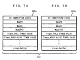
Fig. 7 illustrates a parameter table used in the fourth embodiment.
Protocol parameters for a first logical connection VC1 and protocol
parameters for a second logical connection VC2 are respectively stored in
a first parameter table 122a shown in Fig. 7 (a) and a second parameter
table 122b shown in Fig. 7 (b).
In the fourth embodiment, consider a case where a plurality of logical
connections are set, and different data are transferred with the respective
logical connections. The two logical connections are taken as first and
second logical connections VC1 and VC2, and a destination of connection
of the first logical connection VC1 and a destination of connection of the
second logical connection VC2 are respectively taken as a first device and
a second device.
A data transfer application 14 gives the number of data packets whose
transfer is required at one time to a parameter managing portion 12 for each
logical channel, as in the first embodiment. Correspondingly, a parameter
changing portion 121 in the parameter managing portion 12 previously sets
the number of data packets transferred at one time by the first logical
connection VC1 in MaxPD in the first parameter table 122a, and previously
sets the number of data packets transferred at one time by the second
logical connection VC2 in MaxPD in the second parameter table 122b.
Defaults values shall be set with respect to the other parameters shown in
Fig. 7.
The data transfer application 14 then requires setting of connections
in which addresses of destinations of connection of the two logical connections
VC1 and VC2 are specified of a connection setting portion 13 in order to
connect the logical connections.
When the setting of the logical connections by the connection setting
portion 13 is completed, the data transfer application 14 sets on the first
logical connection VC1 a data link between the data transfer device and the
first device. Similarly, the data transfer application 14 sets on the second
logical connection VC2 a data link between the data transfer device and the
second device. When the setting of the respective data links is completed,
the data transfer application 14 starts the data transfer.
In SSCOP processing, protocol processing is separately performed for
each logical connection. Consequently, different sequence numbers are
assigned to the data packets for each logical connection.
A protocol processing portion 11 produces SD to which a sequence
number for the first device is added upon acceptance of a data transmission
request addressed to the first device from the data transfer application 14,
and transmits the SD to the first device. At this time, the protocol
processing portion 11 increments a count value of a counter for counting the
number of continuously transferred SDs in the first logical connection VC1
(provided inside the protocol processing portion 11) by one, compares the
count value with the value of MaxPD set in the first parameter table 122a,
and sends out POLL if the count value is not less than the value of MaxPD.
The protocol processing portion 11 then produces SD to which a sequence
number for the second device is added upon acceptance of a data request
addressed to the second device from the data transfer application 14, and
transmits the SD to the second device. At this time, the protocol processing
portion 11 increments a count value of a counter for counting the number of
continuously transferred SDs in the second logical connection VC2 (provided
inside the protocol processing portion 11) by one, compares the count value
with the value of MaxPD set in the second parameter table 122b, and sends
out POLL if the count value is not less than the value of MaxPD.
Although in the fourth embodiment, the number of logical channels to
be multiplexed is taken as 2, three or more logical channels can be
multiplexed by managing protocol parameters corresponding to the number
of logical channels to be multiplexed by the parameter managing portion 12.
Although in the fourth embodiment, the number of data packets
transferred at one time is previously set as the value of MaxPD, a method
of setting the value of MaxPD on the basis of a transmission interval of SDs
(a second embodiment) and a method of setting the value of MaxPD on the
basis of NMR designated from a device on the receiving side (a third
embodiment) may be employed. In this case, it is necessary to perform for
each logical channel both monitoring processing in the data transfer
monitoring portion and calculating processing in the parameter calculating
portion.
As described in the foregoing, according to the fourth embodiment,
when the data transfer is made using the plurality of logical channels, the
protocol parameters are separately managed for each of the logical
channels, thereby the data transfer can be made for each logical channel
in the most suitable state.
Although the present invention has been described and illustrated in
detail, it is clearly understood that the same is by way of illustration and
example only and is not to be taken by way of limitation, the spirit and scope
of the present invention being limited only by the terms of the appended
claims.