EP0819835B1 - Umkehrbarer drehrichtungsformer und verdrängungsanlage mit einem solchen umformer - Google Patents
Umkehrbarer drehrichtungsformer und verdrängungsanlage mit einem solchen umformer Download PDFInfo
- Publication number
- EP0819835B1 EP0819835B1 EP96912389A EP96912389A EP0819835B1 EP 0819835 B1 EP0819835 B1 EP 0819835B1 EP 96912389 A EP96912389 A EP 96912389A EP 96912389 A EP96912389 A EP 96912389A EP 0819835 B1 EP0819835 B1 EP 0819835B1
- Authority
- EP
- European Patent Office
- Prior art keywords
- shaft
- guide
- housing
- piston
- converter
- Prior art date
- Legal status (The legal status is an assumption and is not a legal conclusion. Google has not performed a legal analysis and makes no representation as to the accuracy of the status listed.)
- Expired - Lifetime
Links
- 230000002441 reversible effect Effects 0.000 title claims abstract description 15
- 238000006073 displacement reaction Methods 0.000 claims abstract description 36
- 230000007246 mechanism Effects 0.000 claims description 17
- 238000005192 partition Methods 0.000 claims description 13
- 230000010355 oscillation Effects 0.000 claims description 6
- 239000012530 fluid Substances 0.000 description 10
- 239000002609 medium Substances 0.000 description 10
- 238000004519 manufacturing process Methods 0.000 description 6
- 239000007788 liquid Substances 0.000 description 5
- 241000251468 Actinopterygii Species 0.000 description 3
- 238000002347 injection Methods 0.000 description 3
- 239000007924 injection Substances 0.000 description 3
- 238000000034 method Methods 0.000 description 3
- 241000239290 Araneae Species 0.000 description 2
- 230000004308 accommodation Effects 0.000 description 2
- 230000005540 biological transmission Effects 0.000 description 2
- 239000000463 material Substances 0.000 description 2
- 239000000203 mixture Substances 0.000 description 2
- 238000005096 rolling process Methods 0.000 description 2
- 239000003831 antifriction material Substances 0.000 description 1
- 239000011248 coating agent Substances 0.000 description 1
- 238000000576 coating method Methods 0.000 description 1
- 239000002612 dispersion medium Substances 0.000 description 1
- 230000000694 effects Effects 0.000 description 1
- 238000005265 energy consumption Methods 0.000 description 1
- 238000009499 grossing Methods 0.000 description 1
- 238000009776 industrial production Methods 0.000 description 1
- 238000011031 large-scale manufacturing process Methods 0.000 description 1
- 238000005461 lubrication Methods 0.000 description 1
- 238000012856 packing Methods 0.000 description 1
- 230000002093 peripheral effect Effects 0.000 description 1
- 238000002360 preparation method Methods 0.000 description 1
- 238000007789 sealing Methods 0.000 description 1
- 239000007858 starting material Substances 0.000 description 1
- 230000001360 synchronised effect Effects 0.000 description 1
Images




Classifications
-
- F—MECHANICAL ENGINEERING; LIGHTING; HEATING; WEAPONS; BLASTING
- F01—MACHINES OR ENGINES IN GENERAL; ENGINE PLANTS IN GENERAL; STEAM ENGINES
- F01C—ROTARY-PISTON OR OSCILLATING-PISTON MACHINES OR ENGINES
- F01C9/00—Oscillating-piston machines or engines
-
- F—MECHANICAL ENGINEERING; LIGHTING; HEATING; WEAPONS; BLASTING
- F01—MACHINES OR ENGINES IN GENERAL; ENGINE PLANTS IN GENERAL; STEAM ENGINES
- F01C—ROTARY-PISTON OR OSCILLATING-PISTON MACHINES OR ENGINES
- F01C9/00—Oscillating-piston machines or engines
- F01C9/002—Oscillating-piston machines or engines the piston oscillating around a fixed axis
-
- F—MECHANICAL ENGINEERING; LIGHTING; HEATING; WEAPONS; BLASTING
- F04—POSITIVE - DISPLACEMENT MACHINES FOR LIQUIDS; PUMPS FOR LIQUIDS OR ELASTIC FLUIDS
- F04C—ROTARY-PISTON, OR OSCILLATING-PISTON, POSITIVE-DISPLACEMENT MACHINES FOR LIQUIDS; ROTARY-PISTON, OR OSCILLATING-PISTON, POSITIVE-DISPLACEMENT PUMPS
- F04C9/00—Oscillating-piston machines or pumps
Definitions
- the invention relates:
- Said converters can be used:
- Positive displacement machines are widely used in modern engineering. Many of them are products of mass or large-scale production.
- Converters of the direction of motion for positive displacement machines generally comprise a shaft and an optional working element connected (usually rigidly) to the shaft capable either of affecting a fluid (liquid or gaseous) medium during the rotation of the shaft or of taking up the pressure of such medium and converting it into the rotation of the shaft.
- a vane converter of rotary motion comprising a shaft rotatably mounted on at least one bearing and at least one vane preferably radially fixed to the shaft.
- Vane converters and positive displacement machines based thereon are sufficiently widespread and, as a rule, are rather reliable. Some of them have rather high efficiency and specific power.
- a common reversible converter of direction of motion of such type comprises a housing, a shaft rotatably mounted in the housing, a guide rigidly connected to the shaft, and at least one element operatively connected with the guide for taking up the rotation of the shaft or to transmit rotation to the shaft. Then, the geometric axes of rotation of all members cross each other at one point (Ibid. pp. 168-172, Figs. 8.3 and 8.4).
- spherical four-member assembly comprises a body in the form of a carrier ring having projections spaced at an angle of >0° to ⁇ 90°, two shafts jointed in said projections each of which being either an input or an output depending on the connection to an engine and each of which being rigidly connected with guides in the shape of forks (or yokes) articulated at the ends by means of a spider.
- This device serves only for transmission of rotation at an angle to a geometric axis of the input shaft.
- Such machine comrises: a hollow housing having openings at two ends; a transversal partition mounted in the housing and having the shape of a disk comprising a central hole and provided with four tenons being orthogonal to each other and protruding from the housing (serving therefore as a spider); and hollow shafts provided at the outside portions with forks jointly connected to said tenons, said shafts being provided inside the housing with end pistons adapted for oscillation with respect to said partition on the rotation of the shafts at a variable angle the range of variations in which is limited by the sizes of said openings in the housing.
- the open character of the housing and the input/output of the fluid medium provided through the hollow shafts with displacement thereof from one part of the space of the housing at one side of the partition to another part of the space at the other side of the partition substantially complicate the task of providing tightening and make it difficult to utilize the described device.
- the reversible converter of direction of motion in such device is based on a spherical mechanism in which the geometrical axes of rotation of all members cross each other at one central point and which comprises a housing, a shaft rotatably mounted in the housing, a spherical guide operatively connected to the shaft and provided with an annular groove the symmetry plane of which is inclined toward the rotation axis of the shaft and passes through the intersection point of the aformentioned axes, a piston mounted in the housing around the guide for oscillating motion, and at least one intermediate engaging member operatively connected to said groove of the guide and to said piston and adapted for swinging the piston upon the shaft rotation or for rotating the shaft upon oscillating motion of the piston, and a positive displacement machine (particularly a pump or a hydromotor) based on the above described converter comprises a closed hollow spherical housing provided with ports for letting in and out a fluid medium through a valve-controlled mechanism.
- Said housing encloses a piston assembly comprising two pistons.
- One of the pistons is operatively connected to the spherical guide fixed relative to the housing and the other piston encompasses the guide and is rigidly connedted to the (input or output) shaft.
- both of the pistons produce a rotating motion and simultaneously an oscillating motion relative to one another, which reduces reliability due to the intensive friction of the peripheral portions of the piston and the housing.
- said pistons mutually serve as a flywheel mass the driving and supporting rotation of which demands unproductive energy.
- a reversible converter of direction of motion based on a spherical mechanism having geometric axes of rotation of all members intersecting at one central point which comprises a housing, a shaft rotatably mounted in the housing, a spherical guide connected to the shaft and comprising an annular groove having the symmetry plane inclined toward the rotation axis of the shaft and passing through the intersection point of the aformentioned axes, a piston mounted in the housing around the guide for oscillation, and at least one intermediate engaging member operatively connected with said annular groove of the guide and with said piston and being adapted to oscillate the piston during rotation of the shaft or to rotate the shaft during oscillation of the piston,
- the guide is rigidly connected to the shaft
- the piston is formed in the shape of a blade having a central hole enclosing the guide and further operatively connected with the housing by means of two opposed half-axles having the geometric axis intersecting the geometric axis of the shaft in
- Said combination of features characterizes a reversible hydromechanical converter of direction of motion wherein only the shaft with the guide is rotated and the blade alone oscillates, which converter can serve as a unified base for positive displacement machines of various classes.
- the annular groove of the guide is provided with an annular insert moounted flush with the surface of the sphere, said insert having at least one recess adapted for mounting the intermediate engaging member. This provides for the most reliable engagement of the blade with the guide.
- the intermediate engaging member is made in the form of a ball, which reduces loss in the engagenent.
- the housing interior is confined by a cylindrical surface being symmetric about the geometric axis of the half-axles of the blade, and the blade having a central hole is made in the form of rectangular plate.
- Such converter arrangement is useful when utilized in positive displacement metering pumps or flowmeters.
- a positive displacement machine based on a converter of direction of motion in the form of a spherical mechanism having the geometric axes of rotation of all members intersecting at one central point, which comprises a hollow housing confined by the surface of a body of revolution having ports in the walls thereof for injecting and ejecting a fluid medium through a valve-controlled mechanism, a shaft rotatably mounted in the housing, a spherical guide connected to the shaft and comprising an annular groove having the symmetry plane inclined toward the rotation axis of the shaft and passing through the intersection point of the aformentioned axes, a piston mounted in the housing around the guide for oscillating motion, and at least one intermediate engaging member operatively connected with said annular groove of the guide and with said piston and being adapted to swing the piston during rotation of the shaft or to rotate the shaft during oscillating of the piston, according to the invention the guide is rigidly connected to the shaft, and the piston is formed in the shape of
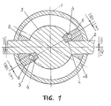
- the positive displacement machine of the invention comprises the following main parts (FIG. 1):
- the shaft 2 can have a through channel, and the guide 3 can be made hollow (as is seen in FIG .6) to facilitate the lubrication of friction surfaces.
- the ring insert 4 can be made:
- the blade 6, enclosing the spherical guide 3, for the convenience of assembly can be made in the form of two parts either butt-jointed or imposed one on another.
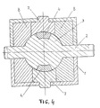
- the blade 6 When used in the housing 1 having a spherical interior, referring to FIG.3, the blade 6 has in the plan view the shape of a ring which can be provided with a suitable outer circumferential seal, and for the housing with a cylindrical interior said blade has the shape of a rectangle, preferably a square (FIG.5) with rounded corners.
- Half-axles 7 can be secured against rotation:
- Housing 1 having a spherical inerior and a ring-shaped blade 6 is preferable when the claimed converter of direction of motion is utilized in combination with such positive displacement machines as pumps and compressors or pneumatic and hydraulic motors; and housing 1 having a cylindrical interior (or a conical interior - not shown) and an appropriately shaped blade 6 is preferable for flowmeters and positive displacement metering pumps.
- the axis of symmetry for cylindrical (or conical) housing 1 in all cases is the geometric axis of the half-axles 7.
- Conical housing can be made by way which can be readily understood by those skilled in the art - in the form of two truncated cones facing each other by the large bases.
- the claimed positive displacement machine with oscillating working elements based on the described converter of direction of motion further comprises the following additional parts (FIG.6):
- said mechanism 10 comprises:
- FIG.6 also schematically illustrates sealing elements 16 and oil ducts 17.
- the distributive disk 12 of the valve-controlled mechanism 10 can be mounted in a recess made in the outer side of the wall of the housing 1 of the machine, suitable ports in the wall of this housing 1 can substitute for pipe connections 9.
- the shaft 2 As the blade 6 of an isolated positive displacement machine suffers from dead centres, it is advisable to provide the shaft 2 with a flywheel.
- the function of said flywheel can perform the very shaft 2 with the guide 3 and the distributive disk 12.
- Pneumatic or hydraulic motors based on the machine of the invention can be provided with the shaft 2 being eccentrically weighted, and in other cases of application, when the shaft 2 is connected to a rotation drive, the function of said flywheel can perform rotative parts of a particular engine.
- pneumatic or hydraulic motors can be preferably formed of at least two claimed positive displacement machines having blades 6 mounted on a common shaft 2 in phase quadrature and which are connected in parallel to a common discharge (or injection) mainline.
- the second variant is preferable as a means of overcoming the dead centres, however in the most cases it is inexpedient and consequently, being clear to the workers in the art, it is not considered here.
- the first variant that is with the housing 1 being fixed, also provides for two modes of operation, namely:
- the guide 3 forces the ring insert 4 to revolve in the annular groove constantly in same direction.
- the ring insert 4 thrusts the ball (or balls) 5 which, rolling in the sockets of the insert 4, force the blade 6 to oscillate.
- the described invention can be realized with the utilization of known in the industry materials, equipment and tools.
Landscapes
- Engineering & Computer Science (AREA)
- Mechanical Engineering (AREA)
- General Engineering & Computer Science (AREA)
- Reciprocating Pumps (AREA)
- Variable-Direction Aerials And Aerial Arrays (AREA)
- Transmission Devices (AREA)
- Analysing Materials By The Use Of Radiation (AREA)
- Transmission Systems Not Characterized By The Medium Used For Transmission (AREA)
- Structures Of Non-Positive Displacement Pumps (AREA)
- Editing Of Facsimile Originals (AREA)
- Extraction Or Liquid Replacement (AREA)
- Aiming, Guidance, Guns With A Light Source, Armor, Camouflage, And Targets (AREA)
- Details Of Reciprocating Pumps (AREA)
- Hydraulic Motors (AREA)
- Rotary Pumps (AREA)
- Control Of Position Or Direction (AREA)
- Automatic Control Of Machine Tools (AREA)
- Compressor (AREA)
- Component Parts Of Construction Machinery (AREA)
Claims (5)
- Reversierbarer Bewegungsrichtungswandler, der auf einem kugelförmigen Mechanismus basiert, bei welchem die geometrische Drehachsen aller Bauteile sich in einem zentralen Punkt schneiden, und der aufweist: ein Gehäuse, eine drehbar im Gehäuse angebrachte Welle, eine kugelförmiges Führungsstück, welches mit der Welle verbunden ist und eine ringförmige Nut aufweist, deren Symmetrieebene zur Drehachse der Welle geneigt ist und durch den Schnittpunkt der zuvor erwähnten Achsen hindurchgeht, einen Kolben, der um das Führungsstück herum im Gehäuse montiert ist, um eine Hin- und Herbewegung auszuführen, und mindestens ein dazwischenliegendes Eingriffselement, das funktionsmäßig mit der ringförmigen Nut des Führungsstücks und mit dem Kolben verbunden ist und geeignet ist, den Kolben während der Drehung der Welle zu schwenken oder die Welle während der Hin- und Herbewegung des Kolbens zu drehen, dadurch gekennzeichnet, daß das Führungsstück starr mit der Welle verbunden ist und der Kolben in Form eines Blattes ausgebildet ist, dessen Mittelloch das Führungsstück umschließt und das weiter mit dem Gehäuse mittels zwei gegenüberliegenden Halbachsen funktionmäßig verbunden ist, deren geometrische Achsen die geometrische Achse der Welle in dem zentralen Punkt schneiden.
- Reversierbarer Wandler nach Anspruch 1, dadurch gekennzeichnet, daß ein ringförmiges Einsatzstück in der ringförmigen Nut des Führungsstücks angebracht ist, und zwar bündig mit der Kugeloberfläche, wobei das Einsatzstück mindestens eine Aussparung zum Anbringen des dazwischenliegenden Eingriffselements besitzt.
- Reversierbarer Wandler nach Anspruch 2, dadurch gekennzeichnet, daß das dazwischenliegende Eingriffselement in Form einer Kugel ausgebildet ist.
- Reversierbarer Wandler nach Anspruch 3, dadurch gekennzeichnet, daß das Gehäuseinnere durch eine zylindrische Fläche begrenzt ist, die symmetrisch um die geometrische Achse der gegenüberliegenden Halbachsen des Blattes ist, und das Blatt, welches ein Mittelloch besitzt, in Form einer Platte von rechteckigem Umfang ausgebildet ist.
- Verdrängermaschine, die auf einem Bewegungsrichtungswandler in Form eines kugelförmigen Mechanismus basiert, bei welchem die geometrische Drehachsen aller Bauteile sich in einem zentralen Punkt schneiden, und die aufweist: ein hohles Gehäuse, welches durch die Oberfläche eines Rotationskörpers begrenzt ist, welcher in seinen Wänden Öffnungen zum Eintritt und Austritt eines Fluidmediums über einen ventilgesteuerten Mechanismus besitzt, eine drehbar im Körper angebrachte Welle, eine kugelförmiges Führungsstück, welches mit der Welle verbunden ist und eine ringförmige Nut aufweist, deren Symmetrieebene zur Drehachse der Welle geneigt ist und durch den Schnittpunkt der zuvor erwähnten Achsen hindurchgeht, einen Kolben, der um das Führungsstück herum im Gehäuse montiert ist, um eine Hin- und Herbewegung auszuführen, und mindestens ein dazwischenliegendes Eingriffselement, das funktionsmäßig mit der ringförmigen Nut des Führungsstücks und mit dem Kolben verbunden ist und geeignet ist, den Kolben während der Drehung der Welle zu schwenken oder die Welle während der Hin- und Herbewegung des Kolbens zu drehen, dadurch gekennzeichnet, daß das Führungsstück starr mit der Welle verbunden ist und der Kolben in Form eines Blattes ausgebildet ist, dessen Mittelloch das Führungsstück eng umschließt und das weiter mit dem Gehäuse mittels zwei gegenüberliegenden Halbachsen fimktionmäßig verbunden ist, deren geometrische Achsen die geometrische Achse der Welle in dem zentralen Punkt schneiden, und ein starres Trennelement im Inneren des Gehäuses angebracht ist, wobei das Trennelement eine Symmetrieebene besitzt, welche die geometrischen Achsen der Welle und der Halbachsen enthält, und mit Aussparungen zur Unterbringung des Führungsstücks und der Halbachsen versehen ist.
Applications Claiming Priority (3)
| Application Number | Priority Date | Filing Date | Title |
|---|---|---|---|
| UA95041532A UA9616C2 (uk) | 1995-04-04 | 1995-04-04 | Силовий агрегат |
| UA95041532 | 1995-04-04 | ||
| PCT/UA1996/000005 WO1996031684A1 (en) | 1995-04-04 | 1996-03-07 | Reversible converter of direction of movement and device for displacing volumes using said converter |
Publications (3)
| Publication Number | Publication Date |
|---|---|
| EP0819835A1 EP0819835A1 (de) | 1998-01-21 |
| EP0819835A4 EP0819835A4 (de) | 1999-11-10 |
| EP0819835B1 true EP0819835B1 (de) | 2003-06-04 |
Family
ID=21689053
Family Applications (1)
| Application Number | Title | Priority Date | Filing Date |
|---|---|---|---|
| EP96912389A Expired - Lifetime EP0819835B1 (de) | 1995-04-04 | 1996-03-07 | Umkehrbarer drehrichtungsformer und verdrängungsanlage mit einem solchen umformer |
Country Status (15)
| Country | Link |
|---|---|
| US (1) | US5993182A (de) |
| EP (1) | EP0819835B1 (de) |
| JP (1) | JP3677660B2 (de) |
| KR (1) | KR19980703581A (de) |
| CN (1) | CN1081723C (de) |
| AT (1) | ATE242421T1 (de) |
| AU (1) | AU694026B2 (de) |
| BR (1) | BR9604810A (de) |
| CA (1) | CA2217219A1 (de) |
| DE (2) | DE69628557T2 (de) |
| ES (1) | ES2113839T1 (de) |
| GR (1) | GR980300030T1 (de) |
| RU (1) | RU2133833C1 (de) |
| UA (1) | UA9616C2 (de) |
| WO (1) | WO1996031684A1 (de) |
Families Citing this family (8)
| Publication number | Priority date | Publication date | Assignee | Title |
|---|---|---|---|---|
| US6325038B1 (en) * | 2000-01-18 | 2001-12-04 | Spherical Propulsion, Llc | Spherical internal combustion engine |
| RU2244163C2 (ru) * | 2002-12-25 | 2005-01-10 | Михаил Михайлович Притула | Сферический кривошипно-ползунный механизм (варианты) |
| ES2307149T3 (es) * | 2004-04-06 | 2008-11-16 | Peraves Aktiengesellschaft | Maquina de piston oscilante y vehiculo con una maquina de piston oscilante de este tipo. |
| CN102345505B (zh) * | 2011-10-15 | 2014-09-17 | 金坛市飞达柴油机配件厂 | 单缸柴油机废气摆扇增压装置 |
| GB201520830D0 (en) | 2015-11-25 | 2016-01-06 | Fenton Jonathan P | Fluid compression apparatus |
| US10323517B2 (en) * | 2016-11-08 | 2019-06-18 | Thomas F. Welker | Multiple axis rotary engine |
| GB2571354B (en) | 2018-02-27 | 2020-04-15 | Fetu Ltd | Roticulating thermodynamic apparatus |
| CN111306586A (zh) * | 2020-02-18 | 2020-06-19 | 广州市绿森环保设备有限公司 | 一种高效曝气装置和采用该曝气装置的气体除味装置 |
Family Cites Families (18)
| Publication number | Priority date | Publication date | Assignee | Title |
|---|---|---|---|---|
| US826985A (en) * | 1905-05-15 | 1906-07-24 | Daniel Appel | Rotary machine. |
| US1952260A (en) * | 1928-12-05 | 1934-03-27 | James L Kempthorne | Rotary engine |
| US1904373A (en) * | 1930-08-20 | 1933-04-18 | James L Kempthorne | Engine |
| US2043544A (en) * | 1933-10-07 | 1936-06-09 | James L Kempthorne | Rotary engine |
| GB1178399A (en) * | 1966-10-03 | 1970-01-21 | Nat Res Dev | Rotary Piston Machines. |
| US3492974A (en) * | 1968-01-30 | 1970-02-03 | Heinrich Kreimeyer | Rotary nutating power device |
| US3730145A (en) * | 1971-04-19 | 1973-05-01 | H Bennetto | Rotary engine |
| SU666286A1 (ru) * | 1974-07-29 | 1979-06-05 | Prochko Evgenij | Аксиально-поршнева гидромашина |
| US3985473A (en) | 1975-07-10 | 1976-10-12 | Copeland Corporation | Rotary pump |
| SU600323A1 (ru) | 1976-01-12 | 1978-03-30 | Предприятие П/Я А-1923 | Объемный двигатель |
| SU1236209A1 (ru) * | 1984-08-08 | 1986-06-07 | Ордена Трудового Красного Знамени Институт Сверхтвердых Материалов Ан Усср | Неполноповоротный гидродвигатель |
| US4631011A (en) | 1985-03-07 | 1986-12-23 | Whitfield Roger R | Fluid handling device useful as a pump, compressor or rotary engine |
| NO160540C (no) * | 1986-11-24 | 1989-04-26 | 3 D Int As | Kraftomsetningsmaskin med stempler som beveges i en dreiebevegelse i et sfaerisk hus. |
| SU1583668A1 (ru) * | 1987-07-03 | 1990-08-07 | Проектно-Конструкторско-Технологическое Бюро По Вагонам | Неполноповоротный пневмодвигатель |
| NO169672C (no) * | 1989-01-09 | 1992-07-22 | 3 D Int As | Kraftomsetningsmaskin med stempler som beveges parvis i forhold til hverandre i et sfaerisk hus. |
| US5074253A (en) * | 1990-02-14 | 1991-12-24 | Georges Dettwiler | Volumetric displacement machine with double-action oscillating pistons |
| US5199864A (en) * | 1990-09-28 | 1993-04-06 | Southwest Research Institute | Spherical fluid pump or motor with spherical ball comprising two parts |
| US5251594A (en) * | 1991-12-31 | 1993-10-12 | Leonard Meyer | Nutating internal combustion engine |
-
1995
- 1995-04-04 UA UA95041532A patent/UA9616C2/uk unknown
-
1996
- 1996-03-07 DE DE69628557T patent/DE69628557T2/de not_active Expired - Fee Related
- 1996-03-07 AU AU55216/96A patent/AU694026B2/en not_active Ceased
- 1996-03-07 AT AT96912389T patent/ATE242421T1/de not_active IP Right Cessation
- 1996-03-07 JP JP53025896A patent/JP3677660B2/ja not_active Expired - Fee Related
- 1996-03-07 CA CA002217219A patent/CA2217219A1/en not_active Abandoned
- 1996-03-07 ES ES96912389T patent/ES2113839T1/es active Pending
- 1996-03-07 CN CN96193685A patent/CN1081723C/zh not_active Expired - Fee Related
- 1996-03-07 KR KR1019970706985A patent/KR19980703581A/ko not_active Withdrawn
- 1996-03-07 BR BR9604810A patent/BR9604810A/pt not_active Application Discontinuation
- 1996-03-07 RU RU97117892A patent/RU2133833C1/ru active
- 1996-03-07 WO PCT/UA1996/000005 patent/WO1996031684A1/ru not_active Ceased
- 1996-03-07 EP EP96912389A patent/EP0819835B1/de not_active Expired - Lifetime
- 1996-03-07 DE DE0819835T patent/DE819835T1/de active Pending
- 1996-03-07 US US08/930,899 patent/US5993182A/en not_active Expired - Fee Related
-
1998
- 1998-05-29 GR GR980300030T patent/GR980300030T1/el unknown
Also Published As
| Publication number | Publication date |
|---|---|
| WO1996031684A1 (en) | 1996-10-10 |
| CN1183132A (zh) | 1998-05-27 |
| ATE242421T1 (de) | 2003-06-15 |
| DE819835T1 (de) | 1998-07-16 |
| MX9707619A (es) | 1998-06-28 |
| RU2133833C1 (ru) | 1999-07-27 |
| EP0819835A1 (de) | 1998-01-21 |
| KR19980703581A (ko) | 1998-11-05 |
| CN1081723C (zh) | 2002-03-27 |
| ES2113839T1 (es) | 1998-05-16 |
| CA2217219A1 (en) | 1996-10-10 |
| UA9616C2 (uk) | 1996-09-30 |
| DE69628557T2 (de) | 2004-04-29 |
| GR980300030T1 (en) | 1998-05-29 |
| US5993182A (en) | 1999-11-30 |
| AU5521696A (en) | 1996-10-23 |
| JP3677660B2 (ja) | 2005-08-03 |
| JPH11503214A (ja) | 1999-03-23 |
| EP0819835A4 (de) | 1999-11-10 |
| BR9604810A (pt) | 1998-06-09 |
| DE69628557D1 (de) | 2003-07-10 |
| AU694026B2 (en) | 1998-07-09 |
Similar Documents
| Publication | Publication Date | Title |
|---|---|---|
| US6659744B1 (en) | Rotary two axis expansible chamber pump with pivotal link | |
| US4844708A (en) | Elliptical-drive oscillating compressor and pump | |
| US4191032A (en) | Rotary energy-transmitting mechanism | |
| US5199864A (en) | Spherical fluid pump or motor with spherical ball comprising two parts | |
| US5171142A (en) | Rotary displacement machine with cylindrical pretension on disc-shaped partition | |
| EP0819835B1 (de) | Umkehrbarer drehrichtungsformer und verdrängungsanlage mit einem solchen umformer | |
| WO1992014036A1 (en) | Pressurized vapor driven rotary engine | |
| EP0210229A1 (de) | Drehkolbenpumpe oder -motor mit schwannkenden flügeln | |
| US7185625B1 (en) | Rotary piston power system | |
| CN101115909A (zh) | 由外部压力源提供的压力介质驱动的马达 | |
| JPS63198701A (ja) | 流体動力トランスファー装置 | |
| US4826402A (en) | High-capacity centrifugal pump | |
| US5219271A (en) | High capacity, high efficiency pump | |
| US5069606A (en) | Rotary fluid displacement apparatus | |
| US2426361A (en) | Variable delivery alternating piston pump | |
| US3924980A (en) | Low friction, controlled leakage rotary engine | |
| MXPA97007619A (en) | Reversible converter of the direction of movement and positive displacement machine based on the mi | |
| KR101488060B1 (ko) | 압축성 매체용 로터리 모터 | |
| US6799955B1 (en) | Two-lobe rotary machine | |
| US11492907B2 (en) | Cartiodal rotary machine with two-lobe rotor | |
| SU1751407A1 (ru) | Роторна машина | |
| RU2100653C1 (ru) | Роторно-лопастная машина | |
| US6212994B1 (en) | Positive displacement rotary machine | |
| RU2130122C1 (ru) | Мотор пневмогидравлический, поршневой, кривошипно-кулисный, роторный, реверсируемый | |
| US1557434A (en) | Compressor |
Legal Events
| Date | Code | Title | Description |
|---|---|---|---|
| PUAI | Public reference made under article 153(3) epc to a published international application that has entered the european phase |
Free format text: ORIGINAL CODE: 0009012 |
|
| 17P | Request for examination filed |
Effective date: 19970929 |
|
| AK | Designated contracting states |
Kind code of ref document: A1 Designated state(s): AT BE CH DE DK ES FI FR GB GR IE IT LI NL PT SE |
|
| ITCL | It: translation for ep claims filed |
Representative=s name: ING. C. GREGORJ S.P.A. |
|
| EL | Fr: translation of claims filed | ||
| TCNL | Nl: translation of patent claims filed | ||
| TCAT | At: translation of patent claims filed | ||
| REG | Reference to a national code |
Ref country code: ES Ref legal event code: BA2A Ref document number: 2113839 Country of ref document: ES Kind code of ref document: T1 |
|
| DET | De: translation of patent claims | ||
| A4 | Supplementary search report drawn up and despatched |
Effective date: 19990924 |
|
| AK | Designated contracting states |
Kind code of ref document: A4 Designated state(s): AT BE CH DE DK ES FI FR GB GR IE IT LI NL PT SE |
|
| GRAH | Despatch of communication of intention to grant a patent |
Free format text: ORIGINAL CODE: EPIDOS IGRA |
|
| GRAH | Despatch of communication of intention to grant a patent |
Free format text: ORIGINAL CODE: EPIDOS IGRA |
|
| GRAA | (expected) grant |
Free format text: ORIGINAL CODE: 0009210 |
|
| AK | Designated contracting states |
Designated state(s): AT BE CH DE DK ES FI FR GB GR IE IT LI NL PT SE |
|
| PG25 | Lapsed in a contracting state [announced via postgrant information from national office to epo] |
Ref country code: NL Free format text: LAPSE BECAUSE OF FAILURE TO SUBMIT A TRANSLATION OF THE DESCRIPTION OR TO PAY THE FEE WITHIN THE PRESCRIBED TIME-LIMIT Effective date: 20030604 Ref country code: FI Free format text: LAPSE BECAUSE OF FAILURE TO SUBMIT A TRANSLATION OF THE DESCRIPTION OR TO PAY THE FEE WITHIN THE PRESCRIBED TIME-LIMIT Effective date: 20030604 Ref country code: BE Free format text: LAPSE BECAUSE OF FAILURE TO SUBMIT A TRANSLATION OF THE DESCRIPTION OR TO PAY THE FEE WITHIN THE PRESCRIBED TIME-LIMIT Effective date: 20030604 Ref country code: AT Free format text: LAPSE BECAUSE OF FAILURE TO SUBMIT A TRANSLATION OF THE DESCRIPTION OR TO PAY THE FEE WITHIN THE PRESCRIBED TIME-LIMIT Effective date: 20030604 |
|
| REG | Reference to a national code |
Ref country code: GB Ref legal event code: FG4D |
|
| REG | Reference to a national code |
Ref country code: CH Ref legal event code: EP |
|
| REG | Reference to a national code |
Ref country code: SE Ref legal event code: TRGR |
|
| REG | Reference to a national code |
Ref country code: IE Ref legal event code: FG4D |
|
| REF | Corresponds to: |
Ref document number: 69628557 Country of ref document: DE Date of ref document: 20030710 Kind code of ref document: P |
|
| REG | Reference to a national code |
Ref country code: CH Ref legal event code: NV Representative=s name: FREI PATENTANWALTSBUERO AG |
|
| PG25 | Lapsed in a contracting state [announced via postgrant information from national office to epo] |
Ref country code: PT Free format text: LAPSE BECAUSE OF FAILURE TO SUBMIT A TRANSLATION OF THE DESCRIPTION OR TO PAY THE FEE WITHIN THE PRESCRIBED TIME-LIMIT Effective date: 20030904 Ref country code: GR Free format text: LAPSE BECAUSE OF FAILURE TO SUBMIT A TRANSLATION OF THE DESCRIPTION OR TO PAY THE FEE WITHIN THE PRESCRIBED TIME-LIMIT Effective date: 20030904 Ref country code: DK Free format text: LAPSE BECAUSE OF FAILURE TO SUBMIT A TRANSLATION OF THE DESCRIPTION OR TO PAY THE FEE WITHIN THE PRESCRIBED TIME-LIMIT Effective date: 20030904 |
|
| PG25 | Lapsed in a contracting state [announced via postgrant information from national office to epo] |
Ref country code: ES Free format text: LAPSE BECAUSE OF FAILURE TO SUBMIT A TRANSLATION OF THE DESCRIPTION OR TO PAY THE FEE WITHIN THE PRESCRIBED TIME-LIMIT Effective date: 20030915 |
|
| NLV1 | Nl: lapsed or annulled due to failure to fulfill the requirements of art. 29p and 29m of the patents act | ||
| PG25 | Lapsed in a contracting state [announced via postgrant information from national office to epo] |
Ref country code: IE Free format text: LAPSE BECAUSE OF NON-PAYMENT OF DUE FEES Effective date: 20040308 |
|
| ET | Fr: translation filed | ||
| PLBE | No opposition filed within time limit |
Free format text: ORIGINAL CODE: 0009261 |
|
| STAA | Information on the status of an ep patent application or granted ep patent |
Free format text: STATUS: NO OPPOSITION FILED WITHIN TIME LIMIT |
|
| 26N | No opposition filed |
Effective date: 20040305 |
|
| REG | Reference to a national code |
Ref country code: IE Ref legal event code: MM4A |
|
| PGFP | Annual fee paid to national office [announced via postgrant information from national office to epo] |
Ref country code: SE Payment date: 20050331 Year of fee payment: 10 |
|
| PGFP | Annual fee paid to national office [announced via postgrant information from national office to epo] |
Ref country code: CH Payment date: 20050405 Year of fee payment: 10 |
|
| PGFP | Annual fee paid to national office [announced via postgrant information from national office to epo] |
Ref country code: DE Payment date: 20050530 Year of fee payment: 10 |
|
| PGFP | Annual fee paid to national office [announced via postgrant information from national office to epo] |
Ref country code: GB Payment date: 20050907 Year of fee payment: 10 |
|
| PGFP | Annual fee paid to national office [announced via postgrant information from national office to epo] |
Ref country code: FR Payment date: 20051003 Year of fee payment: 10 |
|
| PG25 | Lapsed in a contracting state [announced via postgrant information from national office to epo] |
Ref country code: GB Free format text: LAPSE BECAUSE OF NON-PAYMENT OF DUE FEES Effective date: 20060307 |
|
| PG25 | Lapsed in a contracting state [announced via postgrant information from national office to epo] |
Ref country code: SE Free format text: LAPSE BECAUSE OF NON-PAYMENT OF DUE FEES Effective date: 20060308 |
|
| PG25 | Lapsed in a contracting state [announced via postgrant information from national office to epo] |
Ref country code: LI Free format text: LAPSE BECAUSE OF NON-PAYMENT OF DUE FEES Effective date: 20060331 Ref country code: CH Free format text: LAPSE BECAUSE OF NON-PAYMENT OF DUE FEES Effective date: 20060331 |
|
| PGFP | Annual fee paid to national office [announced via postgrant information from national office to epo] |
Ref country code: IT Payment date: 20060331 Year of fee payment: 11 |
|
| PG25 | Lapsed in a contracting state [announced via postgrant information from national office to epo] |
Ref country code: DE Free format text: LAPSE BECAUSE OF NON-PAYMENT OF DUE FEES Effective date: 20061003 |
|
| REG | Reference to a national code |
Ref country code: CH Ref legal event code: PL |
|
| EUG | Se: european patent has lapsed | ||
| GBPC | Gb: european patent ceased through non-payment of renewal fee |
Effective date: 20060307 |
|
| REG | Reference to a national code |
Ref country code: FR Ref legal event code: ST Effective date: 20061130 |
|
| PG25 | Lapsed in a contracting state [announced via postgrant information from national office to epo] |
Ref country code: FR Free format text: LAPSE BECAUSE OF NON-PAYMENT OF DUE FEES Effective date: 20060331 |
|
| PG25 | Lapsed in a contracting state [announced via postgrant information from national office to epo] |
Ref country code: IT Free format text: LAPSE BECAUSE OF NON-PAYMENT OF DUE FEES Effective date: 20070307 |