EP0819197B1 - A drainage installation for roads - Google Patents
A drainage installation for roads Download PDFInfo
- Publication number
- EP0819197B1 EP0819197B1 EP96909322A EP96909322A EP0819197B1 EP 0819197 B1 EP0819197 B1 EP 0819197B1 EP 96909322 A EP96909322 A EP 96909322A EP 96909322 A EP96909322 A EP 96909322A EP 0819197 B1 EP0819197 B1 EP 0819197B1
- Authority
- EP
- European Patent Office
- Prior art keywords
- kerb
- conduit
- roadway
- drainage
- water
- Prior art date
- Legal status (The legal status is an assumption and is not a legal conclusion. Google has not performed a legal analysis and makes no representation as to the accuracy of the status listed.)
- Expired - Lifetime
Links
- 238000009434 installation Methods 0.000 title claims description 13
- XLYOFNOQVPJJNP-UHFFFAOYSA-N water Substances O XLYOFNOQVPJJNP-UHFFFAOYSA-N 0.000 claims abstract description 34
- 239000004567 concrete Substances 0.000 claims abstract description 16
- 239000002352 surface water Substances 0.000 claims abstract description 8
- 230000007704 transition Effects 0.000 claims description 11
- 239000000463 material Substances 0.000 claims description 6
- 238000000465 moulding Methods 0.000 claims description 5
- 239000004033 plastic Substances 0.000 claims description 5
- 229920003023 plastic Polymers 0.000 claims description 5
- 239000004575 stone Substances 0.000 claims description 5
- 238000011065 in-situ storage Methods 0.000 claims description 3
- 239000002184 metal Substances 0.000 claims description 3
- 229910052751 metal Inorganic materials 0.000 claims description 3
- 239000002245 particle Substances 0.000 claims description 3
- 238000000034 method Methods 0.000 claims description 2
- 239000010410 layer Substances 0.000 description 27
- 239000010426 asphalt Substances 0.000 description 8
- 239000002344 surface layer Substances 0.000 description 8
- 238000010276 construction Methods 0.000 description 6
- 239000003351 stiffener Substances 0.000 description 4
- 229910001209 Low-carbon steel Inorganic materials 0.000 description 3
- 230000000295 complement effect Effects 0.000 description 2
- 239000003657 drainage water Substances 0.000 description 2
- 238000004519 manufacturing process Methods 0.000 description 2
- 239000011178 precast concrete Substances 0.000 description 2
- 241000251468 Actinopterygii Species 0.000 description 1
- 229910001018 Cast iron Inorganic materials 0.000 description 1
- 239000002131 composite material Substances 0.000 description 1
- 238000007688 edging Methods 0.000 description 1
- 239000011152 fibreglass Substances 0.000 description 1
- 239000011440 grout Substances 0.000 description 1
- 239000007788 liquid Substances 0.000 description 1
- 229910001092 metal group alloy Inorganic materials 0.000 description 1
- 230000037361 pathway Effects 0.000 description 1
- 239000011148 porous material Substances 0.000 description 1
- 230000000717 retained effect Effects 0.000 description 1
- 125000006850 spacer group Chemical group 0.000 description 1
- 238000005728 strengthening Methods 0.000 description 1
Images






Classifications
-
- E—FIXED CONSTRUCTIONS
- E01—CONSTRUCTION OF ROADS, RAILWAYS, OR BRIDGES
- E01C—CONSTRUCTION OF, OR SURFACES FOR, ROADS, SPORTS GROUNDS, OR THE LIKE; MACHINES OR AUXILIARY TOOLS FOR CONSTRUCTION OR REPAIR
- E01C11/00—Details of pavings
- E01C11/22—Gutters; Kerbs ; Surface drainage of streets, roads or like traffic areas
- E01C11/221—Kerbs or like edging members, e.g. flush kerbs, shoulder retaining means ; Joint members, connecting or load-transfer means specially for kerbs
- E01C11/223—Kerb-and-gutter structures; Kerbs with drainage openings channel or conduits, e.g. with out- or inlets, with integral gutter or with channel formed into the kerb ; Kerbs adapted to house cables or pipes, or to form conduits
-
- E—FIXED CONSTRUCTIONS
- E01—CONSTRUCTION OF ROADS, RAILWAYS, OR BRIDGES
- E01C—CONSTRUCTION OF, OR SURFACES FOR, ROADS, SPORTS GROUNDS, OR THE LIKE; MACHINES OR AUXILIARY TOOLS FOR CONSTRUCTION OR REPAIR
- E01C11/00—Details of pavings
- E01C11/22—Gutters; Kerbs ; Surface drainage of streets, roads or like traffic areas
- E01C11/224—Surface drainage of streets
- E01C11/227—Gutters; Channels ; Roof drainage discharge ducts set in sidewalks
- E01C11/228—Gutters for porous pavings
Definitions
- the invention relates to a drainage installation for roads, and in particular to a kerb drain and gulley system.
- roads as used throughout the specification is intended to include roadways, highways, carriage-ways, bridges, runways and the like.
- a roadway kerb For example, it is known from UK 1591332 to provide a drainage channel formed by a plurality of pre-cast concrete sections laid end to end along the roadway.
- the concrete sections are in the form of blocks having a drainage channel moulded in the center of the block and a cover portion containing a water inlet communicating between the top of the road surface and the channel whereby water may flow from the road surface into the drainage channel.
- the known pre-cast concrete kerb blocks containing an integral drainage channel are difficult and expensive to mould. Also, they are not suitable for draining road surfaces containing a top layer of porous asphalt.
- DE-A-3210222 discloses a kerbstone for edging a roadway, or other surface. It has an edge piece protruding above the roadway and a base piece lying in the ground.
- the base piece contains a duct, extending over the kerbstone's length, with at least one lateral water inflow pipe opening out at road or surface level.
- the base piece can have a plinth, with a water gutter at the level of the road surface or inflow opening.
- Two ducts, such as plastic pipes, can be provided, each with a protrusion and a recess.
- NL-A-9101642 discloses a kerbstone extending along the side of a road surface, having apertures at intervals leading to rainwater collecting chambers.
- the apertures are connected to the chambers by a gutter parallel to the edge of the road surface and close below it.
- the apertures can be less than 5 and preferably less than 2 metres apart, there being on at least in each individual kerbstone.
- the surface has a top layer permeable to liquid with an impermeable one below it, the top one partly making the apertures.
- the kerbstone is of concrete, with the apertures curving through 90 degrees.
- the roadway comprises a road base containing layers of hard core or the like. Above, the road base is laid a dense layer of bitumen macadam, which is largely water impervious.
- the top surface of the roadway is comprised of a layer of porous asphalt laid over the dense layer. With this arrangement rain water percolates through the upper porous asphalt surface of the roadway through to the underlying dense bitumen macadam layer. It is necessary to provide means to remove the percolating water from between the two layers.
- a kerb drain comprises a longitudinal kerb section moulded from concrete or other similar material, the kerb having a top surface, a rear wall, and a front wall, wherein the front wall has formed therein a slot which extends longitudinally of the kerb and in which is located a pre-formed drainage channel which is keyed into the slot during moulding of the kerb, the drainage channel having in a front wall thereof a plurality of apertures through which water may enter a hollow interior of the drainage channel.
- slot is complementary to the shape of the drainage channel such that the drainage channel fits snugly within the slot.
- slot is intended to embrace any longitudinal opening in the kerb suitable to receive the drainage channel preferably with an outer face of the drainage channel substantially flush with the face of the kerb section.
- the slot may be a rabbet, channel-shaped opening or the like.
- the drainage channel comprises a conduit pre-fabricated from metal, plastics, concrete or other suitable material and the kerb is moulded from concrete or the like with the pre-formed conduit located in situ during the moulding process.
- the conduit may be of substantially polygonal shape in cross-section and fits into a complementary shaped rabbet formed in the front wall of the kerb section.
- the conduit may be of rectangular cross section, open at both ends.
- the invention also provides a drainage installation for roadways and the like comprising a road surface, a pavement or verge extending along one or both sides of the roadway, and a kerb located between the roadway and the pavement or verge, wherein the roadway comprises an upper porous layer which is water permeable and an underlayer which is substantially impervious to water, and the kerb is a kerb as described above and wherein the front wall of the conduit containing the apertures is located adjacent to the porous layer such that surface water percolating through the porous layer flows through the apertures and into the hollow interior of the conduit.
- the kerb drains are connected at intervals to junction boxes, which contain a sump, and from which accumulated water may be diverted to a main drainage system.
- a kerb drain of the invention comprises a kerb 1 moulded from concrete or other suitable material.
- the kerb drain 1 is a longitudinal section comprising a top surface 2, a bevelled upper front wall portion 3, a lower wall portion 4 and a rear wall 5.
- the lower wall portion 4 is formed with a longitudinal rabbet 6, which is in the form of a step-shaped rectangular channel.
- the rabbet 6 extends for the full length of the kerb 1 and extends inwardly of the kerb to a depth which is approximately half the width of the kerb 1. For example, if the kerb, when viewed from the end, has a width of 130 mm, the rabbet 6 has a width of 60 mm.
- the rabbet 6 is adapted to receive an enclosed drainage channel in the form of a conduit 7.
- the conduit 7 is substantially rectangular, in cross-section, and comprises a top wall 8, a bottom wall 9, a rear wall 10 and a front wall 11. It will be appreciated that the rearwall 10 and/or the bottom wall 9 of the conduit 7 could be omitted in which case the conduit 7 would be of open-channel shape or L-shape in cross-section. In that event, the top and side walls defining the rabbet 6 would co-operate with the walls of the conduit 7 to form a drainage channel.
- the front wall 11 of the conduit 7 is formed with a plurality of slots 12 at spaced intervals along the length of the wall.
- the slots 12 form apertures through the wall through which water may flow into a hollow interior of the conduit 7.
- the conduit 7 is keyed into the rabbet 6 by means of ties 13 which are fixed to and project from the rear wall 10 of the conduit 7 and extend into the concrete of the kerb 1.
- the ties 13 are in the shape of fish tails.
- the conduit 7 is fabricated from galvanised mild steel from which it is pressed, and slotted to form the slots 12.
- the conduit 7 may be made from 4-6 mm mild steel.
- channel 7 can be made from metal alloy, cast-iron, plastics, concrete or other suitable material.
- the conduit 7 is of a rectangular cross-section, but it could be of square, circular, c-shaped or other cross-section.
- the ties 13 are welded to the rear wall 10 of the conduit 7 at spaced intervals.
- the conduit 7 is placed into a mould having the shape of the kerb 1. Concrete, for example 25 newtons, air-entrained concrete, is poured into the mould in well known manner and allowed to cure. In this way, the kerb 1 is cast with the conduit 7 located in situ.
- the roadway 14 comprises an upper porous surface layer 16 of asphalt, which is laid on an underlying dense layer 17 which is substantially impervious to water.
- the dense layer 17 is supported on a road base 18 formed from hard core or the like.
- the pavement or verge 15 extends along one or both sides of the roadway 14, and has a surface which is elevated relative to the surface of the road.
- the kerb 1 extends upwardly from the road surface 14 and abuts the edge of the pavement 15.
- the rear wall 5 of the kerb 1 abuts the pavement 15, and the upper wall portion 3 and the lower wall portion 4 face the roadway.
- the conduit 7 is located substantially below the road surface.
- the upper portion of the front wall 11 of the conduit 7, which contains the slots 12, is located adjacent to the porous surface layer 16 of the roadway.
- a lower, closed, portion of the wall 11 is located adjacent to the intermediate dense layer 17 of the roadway.
- the number, spacing and size of the slots 12 is of importance. Thus, it is of importance that the slots 12 communicate with the porous asphalt layer 16 and also communicate with the joint between the layer 16 and the intermediate dense layer 17 so that all water percolating through the upper porous layer 16 is collected in the conduit 7. If desired, an upper portion of the slotted part of the wall 11 may be positioned above the surface of the roadway 14 to facilitate collection of surface water. It is important that the width of the slots 12 is less than the average diameter (particle size) of the stone chips which are used in forming the porous asphalt surface layer 16. In a typical arrangement, the chips used in forming the surface layer 16 have a minimum size of 20 mm.
- the slots 12 are 10 mm in width and 52 mm in height.
- the slots are spaced apart at 10 mm intervals. Thus, should the stone chips forming the upper surface layer 16 of the roadway become loose, they cannot enter through the slots 12.
- the kerbs 1 are laid end to end along the side of the roadway.
- the conduit 7 projects a short distance, typically 6 mm, from each end of the concrete kerb 1 as shown in Figure 1.
- the projecting portions 19 of the conduit 7 act as spacers to create a gap between adjoining kerbs 1.
- These gaps are filled with grout to seal the joint between the kerb sections.
- a seating plate 20 is attached to one end of the bottom wall 9 of the conduit 7 and projects laterally therefrom. The seating plate 20 facilitates levelling of adjoining kerbs 1.
- junction boxes 21 are connected to the kerb 1 at intervals, which may vary from about 10 meter intervals to 30 meter intervals depending on the expected water flow.
- the junction box 21 has, in an upper corner thereof, an inlet section 22 which, in cross-section, is of substantially the same shape as the kerb 1.
- the junction box 21 is buried in the ground to a depth such that inlet section 22 abuts adjoining kerbs 1.
- the inlet section 22 suitably is made from metal.
- the remainder of the junction box may be moulded from concrete, plastics or the like. It could also be fabricated from glass reinforced plastics.
- the inlet section 22 includes an inlet 23 which corresponds in size and shape to the conduit 7 and connects with the conduit 7. Thus, water from the conduit 7 flows into the inlet 23 and from there into the interior of the junction box 21.
- the junction box 21 has a hollow interior 24 including a lower sump 25.
- the junction box 21 is provided with an outlet 26, a lower portion of which is positioned just below the level of the inlet 23.
- the outlet 26 is adapted to receive a connector pipe (not shown) which is connected to the main drainage system.
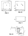
- the junction box 21 is formed with a cover 27.
- the cover 27 is fabricated from 4 mm galvanised mild steel with an anti-slip top surface.
- the cover has a flat top portion 28 which is aligned with the surface of the pavement 15.
- a front portion 29 of the cover 27 is bent to a profile which corresponds with the front profile of the kerb 1.
- the cover 27 is shown in more detail in Figures 10 to 12.
- the top 28 is provided with two locks 30.
- the construction of the lock 30 is illustrated in Figure 12.
- Each lock 30 comprises a rotatable bolt 31 which is journaled in upper and lower bearings 32 contained in a frame 33 welded to the underside of the top 28 of the cover 27.
- the bolt 31 has a bolt head 34 by means of which the bolt 31 may be rotated by a suitable key or wrench, for example an allen key.
- the bolt head 34 is recessed within the top 28.
- the bolt has, at its lower end, a foot 35 which projects at right angles from the bolt. When the bolt is in the closed position the foot 35 engages in a slot 36 formed in the side wall at the junction box 21. To open the lock the bolt 31 is rotated to disengage the foot 35 from the slot 36, whereupon the cover 27 may be lifted off the junction box 21.
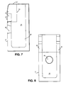
- the junction box illustrated in Figures 7 to 9 is substantially the same in construction as that of Figures 4 to 6, and like numerals denote like parts.
- the main difference is that in the embodiment of Figures 4 to 6, the outlet 26 is located in the rear wall of the junction box, whereas in the embodiment of Figures 7 to 9, the outlet 26 is located in the front wall of the junction box.
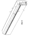
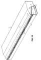
- the kerb shown and described in Figures 13 to 15 is generally similar in construction to the kerb 1 described with reference to Figures 1 to 3, except that the slots 12 are positioned at a higher location in the kerb, such that in use the slots are adjacent the surface layer of the roadway, and are thus suitable for removing surface water from a roadway 14. Many roadways do not have a semi-permeable top layer and thus water is retained on the surface layer 16 of the road.
- the kerb 1 of this embodiment has a top surface 2 and a bevelled upper front wall portion 3.
- the conduit 7 is substantially rectangular, in cross section and again comprises a top wall 8, a bottom wall 9, a rear wall 10 and a front wall 11.
- the rear wall 10 and the front wall 11 are substantially longer than the side walls 8 and 9 thus giving the conduit 7 an overall elongate rectangular shape.
- the conduit 7 extends vertically close to the top surface 2 of the kerb 1.
- the conduit 7 also has attached a toe plate 37.
- the toe-plate 37 is an extended part of the conduit which extends above the top wall 8 of the conduit 7 and follows the profile of the bevelled upper front wall portion 3 of the kerb.
- the toe plate 37 extends laterally along the entire length of the conduit 7 and the kerb 1.
- the toe plate protects the front wall 3 from chipping and other damage. It also serves in locating the conduit accurately in the rabbet 6 during moulding of the kerb 1, and helps in strengthening the construction.
- top corner portion of the front wall 11 of the conduit 7 is bevelled to conform to the shape of the bevelled front wall 3 of the kerb.
- the corner between top wall 8 and front wall 11 is thus defined by an angled portion 38.
- the slots 12 are formed in the bevelled portion of the front wall 11 of the conduit 7. The result is that ribs 39 between the slots 12 also have an angled profile, and the slots 12 lie in the bevelled plane.
- the kerb 1 is fitted between a roadway 14 and a path or verge 15.
- the roadway 14 is composed of three layers. Firstly there is the road base 18, an intermediate dense layer 17 and an upper impervious layer 40. The kerb is fitted in place so that the angled portion 38 of the conduit 7 and begins just above the upper impervious layer 40. Therefore the slots 12 are above the surface of the impervious layer 40 and surface water runs off the upper layer 40 through the slots 12 and into the conduit 7 as described previously.
- the toe plate 37 is provided with a stiffener 41 which strengthens the toe plate 37.
- the stiffener 41 does not extend laterally along the toe plate 37 but instead a number of stiffeners 41 are provided at intervals along toe plate 37.
- the rabbet 6 in the kerb 1 is suitably shaped at the top thereof to accommodate the bevelled shape of the toe plate 37, such that it is flush with the wall 3.
- a junction box 21 suitable for use with the kerb 1 of Figure 13 is now described with reference to Figures 16 to 18.
- the junction box 21 has, in an upper corner thereof, an inlet section 22 which, in cross section is of substantially the same shape as the kerb 1 of Figure 13.
- the junction box 21 functions in exactly the same way as described for the previous embodiment.
- Figures 16(a) and 16(b) show two alternate arrangements whereby the outlet 26 is provided in the rear wall and front wall of the junction box respectively.
- the junction box 21 has a cover 27 which has a flat top portion 28 and a
- a cover 27 for the junction box is comprised of a flat top portion 28 and a front plate 29.
- the top 28 is provided with a locking arrangement 30 which functions as described previously with reference of Figure 12.
- the top 28 is provided with a lip 42 which extends over the front plate 29 when the junction box is assembled.
- the kerb 1 shown in Figure 19 is a low profile kerb being of substantially shorter vertical height than the kerbs of the two embodiments described previously.
- the conduit 7 again is of a different cross-sectional shape.
- the vertical, front wall 11 and rear wall 10 of the conduit are shorter than the transverse walls 8 and 9.
- front wall 11 is higher than rear wall 10.
- Top wall 8 thus slopes downwardly from where it meets front wall 11 to where it joins rear wall 10.
- the cross-section of the conduit 7 thus retains its volume capacity for water while being substantially reduced in height.
- the conduit 7 is fitted with a toe plate 37 which is similar in construction, and serves the same function as that described above in relation to Figures 13 to 15. Similarly, slots 12 are provided in the conduit 7 on the front wall 11.
- the kerb 1 of this embodiment is particularly designed to be used where a reduced height difference between a roadway and a elevated surface is required for instance between a roadway and a roundabout, or an island, or a path.
- the kerb 1 may also be used where the kerb is positioned in front of gateways, at pedestrian crossings and the like.
- the strength of the kerb is not affected as the sloping of the top wall 8 allows sufficient amount of the composite material of kerb 1 above the conduit 7 to give the kerb 1 sufficient strength.
- This third embodiment of the kerb may be used either where the slots 12 are located at a level beneath the surface level of a roadway where the roadway has an upper porous surface. Alternatively it may be used where the slots 12 are located at a level above the level of a roadway where the upper surface is comprised of a non-porous material and the surface water runs off the top surface of the roadway.
- Figure 21 shows the third embodiment in place between a roadway and a pathway. Stiffeners 41 are provided on the toe plate 37. As can be seen from Figure 21 the toe plate 37 follows the profile of the kerb 1 and the outer surface of the toe plate 37 is flush with the surface of the kerb.
- FIGS 22(a) and 22(b) show alternate junction boxes 21 suitable for use with the kerb 1 of the third embodiment.
- Each junction box 21 has a similar cross-sectional shape to the kerb 1 and function in a manner exactly analagous to the junction boxes described previously.
- the cover 27 again comprises a front portion 29 and a top portion 28.
- the cover portion 28 and the front portion 29 fit onto the junction box 21 again as described previously.
- the locking arrangement 30 is as described previously and is used to hold the cover 27 in place.
- transition piece or kerb 41 as shown in Figures 25 may be used.
- transition refers to a kerb which is adapted at its opposite ends to accommodate different types of kerb. This transition kerb may be used to connect a taller kerb of the embodiment of Figure 1 to a low profile kerb of the embodiment of Figure 19.
- the transition kerb may also be used where for instance the top surface layer of the roadway changes from being permeable to being non-permeable or vice versa and where different versions of the kerb are used.
- the transition kerb contains a conduit 42 which interconnects with the conduits 7 of the adjacent kerbs and thus ensures a continuous channel for drainage water.
- the top surface 43 of the transition kerb is sloped so as to be flush with the top surface of each of the adjacent kerbs 1.
- An alternative version of the transition kerb 41 joins a low profile kerb to a higher one, the slope of top surface 43 being reversed.
- the conduit 42 may optionally contain slots to collect drainage water.
- the top surface 43 of the transition kerb is sloped so as to be flush with the top surface of each of the adjcacent kerbs 1.
- kerb drains of the invention are shown as straight sections. It will be appreciated however, that the kerb drains may be curved and/or mitred for use with roundabouts and other curved or circular roadway verges. Also the kerb drain sections may vary in length.
Landscapes
- Engineering & Computer Science (AREA)
- Architecture (AREA)
- Civil Engineering (AREA)
- Structural Engineering (AREA)
- Road Paving Structures (AREA)
- Bridges Or Land Bridges (AREA)
- Sewage (AREA)
- Road Signs Or Road Markings (AREA)
- Cyclones (AREA)
- Treatment Of Sludge (AREA)
- Prostheses (AREA)
Abstract
Description
Claims (11)
- A kerb drain comprising a longitudinal kerb section (1) moulded from concrete or similar material, the kerb (1) having a top surface (2), a rear wall (5), and a front wall portion (4), wherein the front wall portion (4) has formed therein a slot (6) which extends longitudinally of the kerb (1) and in which is located a pre-formed drainage channel (7) which is keyed into the slot (6) during moulding of the kerb (1), the drainage channel (7) having in a front portion (11) thereof a plurality of apertures (12) through which water may enter a hollow interior of the drainage channel (7).
- A kerb drain as claimed in Claim 1 characterised in that the drainage channel comprises a conduit (7) pre-fabricated from metal, plastics, concrete or other suitable material and the kerb (1) is moulded from concrete or the like with the pre-formed conduit (7) located in situ during the moulding process.
- A kerb drain as claimed in any of the preceding claims characterised in that the conduit (7) is of substantially polygonal shape in cross-section and fits into a rabbet (6) formed in the front wall of the kerb section (1).
- A kerb drain as claimed in any of the preceding claims characterised in that the kerb section (1) has a bevelled front wall portion (3).
- A kerb drain as claimed in Claim 4 characterised in that the pre-formed drainage channel (7) has an upwardly extending plate (37) which is shaped to conform to the bevelled shape of the front wall portion (3) of the kerb section (1) and is moulded into said wall portion so as to be flush therewith.
- A drainage installation for roadways and the like comprising a roadway (14), a pavement or verge (15) extending along one or both sides of the roadway, and a kerb (1) located between the roadway (14) and the pavement or verge (15) wherein the roadway comprises an upper porous layer (16) which is water permeable and an underlay (17) which is substantially impervious to water, characterised in that the kerb (1) is a kerb drain as claimed in any of the preceding claims.
- A drainage installation as claimed in Claim 6, characterised in that the apertures (12) are located adjacent to the porous layer (16) such that surface water percolating through the porous layer flows through the apertures (12) and into the hollow interior of the channel (7).
- A drainage installation as claimed in Claim 6 or Claim 7 characterised in that a plurality of kerb drains (1) are laid end to end along the roadway and are connected at intervals to junction boxes (21), which contain a sump (25), and from which accumulated water may be diverted to a main drainage system.
- A drainage installation as claimed in any of Claims 6 to 8 characterised in that the porous layer (16) contains stone chips and the size of the apertures (12) is less than the average particle size of the stone chips such that the stone chips may not pass through the apertures (12).
- A drainage installation as claimed in Claim 8, characterised in that the junction boxes have an inlet (23) which corresponds substantially in size and shape to the conduit (7) and connects with the conduit (7).
- A drainage installation as claimed in any of Claims 6 to 10, characterised in that the kerb drains (1) in one section of the roadway (14) are of a different height to those in another section, and a transition kerb (41) is provided to join the two sections of kerb, the transition kerb (41) having a conduit (42) which connects to the conduits (7) of adjacent kerbs.
Applications Claiming Priority (3)
| Application Number | Priority Date | Filing Date | Title |
|---|---|---|---|
| IE950251 IES67878B2 (en) | 1995-04-06 | 1995-04-06 | A drainage installation for roads |
| IE950251 | 1995-04-06 | ||
| PCT/IE1996/000020 WO1996031657A1 (en) | 1995-04-06 | 1996-04-04 | A drainage installation for roads |
Publications (2)
| Publication Number | Publication Date |
|---|---|
| EP0819197A1 EP0819197A1 (en) | 1998-01-21 |
| EP0819197B1 true EP0819197B1 (en) | 1999-01-07 |
Family
ID=11040711
Family Applications (1)
| Application Number | Title | Priority Date | Filing Date |
|---|---|---|---|
| EP96909322A Expired - Lifetime EP0819197B1 (en) | 1995-04-06 | 1996-04-04 | A drainage installation for roads |
Country Status (7)
| Country | Link |
|---|---|
| EP (1) | EP0819197B1 (en) |
| AT (1) | ATE175457T1 (en) |
| AU (1) | AU5286996A (en) |
| DE (1) | DE69601306T2 (en) |
| GB (1) | GB2299605B (en) |
| IE (1) | IES67878B2 (en) |
| WO (1) | WO1996031657A1 (en) |
Families Citing this family (8)
| Publication number | Priority date | Publication date | Assignee | Title |
|---|---|---|---|---|
| AU706169B3 (en) * | 1999-03-09 | 1999-06-10 | Larence Edwin Anderson | A screen assembly for a road gutter |
| AU2008201960B2 (en) * | 2007-05-03 | 2014-09-11 | Phillip Anthony Thomas | Green gully |
| CN102587253B (en) * | 2012-02-01 | 2014-07-02 | 北京林大林业科技股份有限公司 | Method for paving highway sideway curb |
| CN106758673A (en) * | 2017-01-24 | 2017-05-31 | 苏交科集团股份有限公司 | A kind of Prefabricated block and Prefabricated block group for roadside drainage |
| WO2018226083A1 (en) | 2017-06-06 | 2018-12-13 | ANTEVSKA, Aneta | Kerb |
| JP2019167723A (en) * | 2018-03-23 | 2019-10-03 | 日鉄建材株式会社 | Curb-integrated steel drain gutter |
| WO2024099532A1 (en) | 2022-11-07 | 2024-05-16 | Pierburg Gmbh | Kerb charging device for charging an energy store of an electrically driven vehicle |
| CN116536998B (en) * | 2023-05-17 | 2025-07-29 | 福建诚铄建设工程有限公司 | Prefabricated assembled road structure |
Family Cites Families (5)
| Publication number | Priority date | Publication date | Assignee | Title |
|---|---|---|---|---|
| GB436398A (en) * | 1934-04-18 | 1935-10-10 | Steven Norris | An improved system of road construction |
| GB1591332A (en) * | 1978-03-03 | 1981-06-17 | Althon Contracting Ltd | Drainage of roads and highways |
| CH652776A5 (en) * | 1981-03-23 | 1985-11-29 | Alex Strub | Curb. |
| DE9103590U1 (en) * | 1991-03-23 | 1991-06-27 | Birco Baustoffwerk GmbH, 7570 Baden-Baden | Drainage channel with top cover |
| NL9101642A (en) * | 1991-09-27 | 1993-04-16 | Struyk Holding B V | Element which is suitable for a road or the like |
-
1995
- 1995-04-06 IE IE950251 patent/IES67878B2/en not_active IP Right Cessation
- 1995-10-09 GB GB9520590A patent/GB2299605B/en not_active Expired - Fee Related
-
1996
- 1996-04-04 DE DE69601306T patent/DE69601306T2/en not_active Expired - Lifetime
- 1996-04-04 EP EP96909322A patent/EP0819197B1/en not_active Expired - Lifetime
- 1996-04-04 AU AU52869/96A patent/AU5286996A/en not_active Abandoned
- 1996-04-04 AT AT96909322T patent/ATE175457T1/en not_active IP Right Cessation
- 1996-04-04 WO PCT/IE1996/000020 patent/WO1996031657A1/en not_active Ceased
Also Published As
| Publication number | Publication date |
|---|---|
| IES950251A2 (en) | 1996-05-01 |
| WO1996031657A1 (en) | 1996-10-10 |
| GB2299605B (en) | 1997-04-02 |
| DE69601306D1 (en) | 1999-02-18 |
| GB9520590D0 (en) | 1995-12-13 |
| IES67878B2 (en) | 1996-05-01 |
| ATE175457T1 (en) | 1999-01-15 |
| GB2299605A (en) | 1996-10-09 |
| DE69601306T2 (en) | 1999-07-15 |
| EP0819197A1 (en) | 1998-01-21 |
| AU5286996A (en) | 1996-10-23 |
Similar Documents
| Publication | Publication Date | Title |
|---|---|---|
| JP2007138707A (en) | Boundary block between sidewalk and roadway for water permeable pavement and drainage structure of water permeable pavement | |
| KR101282914B1 (en) | Drainage system of pavement | |
| EP0819197A1 (en) | A drainage installation for roads | |
| JP2007100506A (en) | Drainage basin and drainage structure of paved road using this | |
| JPH0786247B2 (en) | Multifunctional gutter | |
| JP4125834B2 (en) | Gutter, gutter lid member, and boundary block | |
| IE960277A1 (en) | A drainage installation for roads | |
| JP2001279607A (en) | Boundary block and drain treatment structure of road | |
| JPH10183729A (en) | Drainage channel for draining pavement | |
| JP4250719B2 (en) | Boundary water channel block | |
| JP2011047107A (en) | Sidewalk roadway boundary block, and sidewalk roadway boundary drainage structure | |
| JP2000328641A (en) | Side drain with lid slab having curb | |
| JP3876155B2 (en) | Pedestrian road boundary gutter block | |
| JPH05339978A (en) | Composite function type gutter | |
| JP3334947B2 (en) | Structure of permeable pavement culvert and culvert block | |
| JP2000045212A (en) | Boundary block | |
| KR100647210B1 (en) | Side mouth integrated with boundary stone | |
| JP4587430B2 (en) | Road gutter installation structure | |
| NL2039966B1 (en) | Infrastructural gutter module | |
| JP2000345508A (en) | Sidewalk and roadway boundary block for water permeable paving and drainage structure of water permeable pavement | |
| NL9101642A (en) | Element which is suitable for a road or the like | |
| JP2559319Y2 (en) | Road side gutter block body | |
| JPH08199504A (en) | Side ditch | |
| JPS6131044Y2 (en) | ||
| JP3049872U (en) | Easy-to-plant sidewalk block |
Legal Events
| Date | Code | Title | Description |
|---|---|---|---|
| PUAI | Public reference made under article 153(3) epc to a published international application that has entered the european phase |
Free format text: ORIGINAL CODE: 0009012 |
|
| 17P | Request for examination filed |
Effective date: 19971021 |
|
| AK | Designated contracting states |
Kind code of ref document: A1 Designated state(s): AT BE CH DE DK ES FI FR GB GR IE IT LI LU MC NL PT SE |
|
| GRAG | Despatch of communication of intention to grant |
Free format text: ORIGINAL CODE: EPIDOS AGRA |
|
| 17Q | First examination report despatched |
Effective date: 19980212 |
|
| GRAG | Despatch of communication of intention to grant |
Free format text: ORIGINAL CODE: EPIDOS AGRA |
|
| GRAH | Despatch of communication of intention to grant a patent |
Free format text: ORIGINAL CODE: EPIDOS IGRA |
|
| GRAH | Despatch of communication of intention to grant a patent |
Free format text: ORIGINAL CODE: EPIDOS IGRA |
|
| GRAA | (expected) grant |
Free format text: ORIGINAL CODE: 0009210 |
|
| AK | Designated contracting states |
Kind code of ref document: B1 Designated state(s): AT BE CH DE DK ES FI FR GB GR IE IT LI LU MC NL PT SE |
|
| PG25 | Lapsed in a contracting state [announced via postgrant information from national office to epo] |
Ref country code: SE Free format text: THE PATENT HAS BEEN ANNULLED BY A DECISION OF A NATIONAL AUTHORITY Effective date: 19990107 Ref country code: NL Free format text: LAPSE BECAUSE OF FAILURE TO SUBMIT A TRANSLATION OF THE DESCRIPTION OR TO PAY THE FEE WITHIN THE PRESCRIBED TIME-LIMIT Effective date: 19990107 Ref country code: LI Free format text: LAPSE BECAUSE OF FAILURE TO SUBMIT A TRANSLATION OF THE DESCRIPTION OR TO PAY THE FEE WITHIN THE PRESCRIBED TIME-LIMIT Effective date: 19990107 Ref country code: IT Free format text: LAPSE BECAUSE OF FAILURE TO SUBMIT A TRANSLATION OF THE DESCRIPTION OR TO PAY THE FEE WITHIN THE PRESCRIBED TIME-LIMIT;WARNING: LAPSES OF ITALIAN PATENTS WITH EFFECTIVE DATE BEFORE 2007 MAY HAVE OCCURRED AT ANY TIME BEFORE 2007. THE CORRECT EFFECTIVE DATE MAY BE DIFFERENT FROM THE ONE RECORDED. Effective date: 19990107 Ref country code: GR Free format text: LAPSE BECAUSE OF NON-PAYMENT OF DUE FEES Effective date: 19990107 Ref country code: FI Free format text: LAPSE BECAUSE OF NON-PAYMENT OF DUE FEES Effective date: 19990107 Ref country code: ES Free format text: THE PATENT HAS BEEN ANNULLED BY A DECISION OF A NATIONAL AUTHORITY Effective date: 19990107 Ref country code: CH Free format text: LAPSE BECAUSE OF FAILURE TO SUBMIT A TRANSLATION OF THE DESCRIPTION OR TO PAY THE FEE WITHIN THE PRESCRIBED TIME-LIMIT Effective date: 19990107 Ref country code: BE Free format text: LAPSE BECAUSE OF FAILURE TO SUBMIT A TRANSLATION OF THE DESCRIPTION OR TO PAY THE FEE WITHIN THE PRESCRIBED TIME-LIMIT Effective date: 19990107 Ref country code: AT Free format text: LAPSE BECAUSE OF FAILURE TO SUBMIT A TRANSLATION OF THE DESCRIPTION OR TO PAY THE FEE WITHIN THE PRESCRIBED TIME-LIMIT Effective date: 19990107 |
|
| REF | Corresponds to: |
Ref document number: 175457 Country of ref document: AT Date of ref document: 19990115 Kind code of ref document: T |
|
| REG | Reference to a national code |
Ref country code: CH Ref legal event code: EP |
|
| REF | Corresponds to: |
Ref document number: 69601306 Country of ref document: DE Date of ref document: 19990218 |
|
| REG | Reference to a national code |
Ref country code: IE Ref legal event code: FG4D |
|
| ET | Fr: translation filed | ||
| PG25 | Lapsed in a contracting state [announced via postgrant information from national office to epo] |
Ref country code: LU Free format text: LAPSE BECAUSE OF NON-PAYMENT OF DUE FEES Effective date: 19990404 |
|
| PG25 | Lapsed in a contracting state [announced via postgrant information from national office to epo] |
Ref country code: PT Free format text: LAPSE BECAUSE OF FAILURE TO SUBMIT A TRANSLATION OF THE DESCRIPTION OR TO PAY THE FEE WITHIN THE PRESCRIBED TIME-LIMIT Effective date: 19990407 Ref country code: DK Free format text: LAPSE BECAUSE OF FAILURE TO SUBMIT A TRANSLATION OF THE DESCRIPTION OR TO PAY THE FEE WITHIN THE PRESCRIBED TIME-LIMIT Effective date: 19990407 |
|
| NLV1 | Nl: lapsed or annulled due to failure to fulfill the requirements of art. 29p and 29m of the patents act | ||
| REG | Reference to a national code |
Ref country code: CH Ref legal event code: PL |
|
| PG25 | Lapsed in a contracting state [announced via postgrant information from national office to epo] |
Ref country code: MC Free format text: LAPSE BECAUSE OF NON-PAYMENT OF DUE FEES Effective date: 19991031 |
|
| PLBE | No opposition filed within time limit |
Free format text: ORIGINAL CODE: 0009261 |
|
| STAA | Information on the status of an ep patent application or granted ep patent |
Free format text: STATUS: NO OPPOSITION FILED WITHIN TIME LIMIT |
|
| 26N | No opposition filed | ||
| REG | Reference to a national code |
Ref country code: GB Ref legal event code: IF02 |
|
| PGFP | Annual fee paid to national office [announced via postgrant information from national office to epo] |
Ref country code: IE Payment date: 20110321 Year of fee payment: 16 |
|
| PGFP | Annual fee paid to national office [announced via postgrant information from national office to epo] |
Ref country code: FR Payment date: 20110419 Year of fee payment: 16 Ref country code: GB Payment date: 20110325 Year of fee payment: 16 |
|
| PGFP | Annual fee paid to national office [announced via postgrant information from national office to epo] |
Ref country code: DE Payment date: 20110629 Year of fee payment: 16 |
|
| GBPC | Gb: european patent ceased through non-payment of renewal fee |
Effective date: 20120404 |
|
| REG | Reference to a national code |
Ref country code: IE Ref legal event code: MM4A |
|
| REG | Reference to a national code |
Ref country code: FR Ref legal event code: ST Effective date: 20121228 |
|
| PG25 | Lapsed in a contracting state [announced via postgrant information from national office to epo] |
Ref country code: GB Free format text: LAPSE BECAUSE OF NON-PAYMENT OF DUE FEES Effective date: 20120404 Ref country code: IE Free format text: LAPSE BECAUSE OF NON-PAYMENT OF DUE FEES Effective date: 20120404 |
|
| REG | Reference to a national code |
Ref country code: DE Ref legal event code: R119 Ref document number: 69601306 Country of ref document: DE Effective date: 20121101 |
|
| PG25 | Lapsed in a contracting state [announced via postgrant information from national office to epo] |
Ref country code: FR Free format text: LAPSE BECAUSE OF NON-PAYMENT OF DUE FEES Effective date: 20120430 |
|
| PG25 | Lapsed in a contracting state [announced via postgrant information from national office to epo] |
Ref country code: DE Free format text: LAPSE BECAUSE OF NON-PAYMENT OF DUE FEES Effective date: 20121101 |