EP0817697B1 - Rotierender faseroptischer koppler für die anpassungen des hochleistungslaserschweissens - Google Patents
Rotierender faseroptischer koppler für die anpassungen des hochleistungslaserschweissens Download PDFInfo
- Publication number
- EP0817697B1 EP0817697B1 EP96910684A EP96910684A EP0817697B1 EP 0817697 B1 EP0817697 B1 EP 0817697B1 EP 96910684 A EP96910684 A EP 96910684A EP 96910684 A EP96910684 A EP 96910684A EP 0817697 B1 EP0817697 B1 EP 0817697B1
- Authority
- EP
- European Patent Office
- Prior art keywords
- rotating
- tube
- fiber optic
- sleeve
- laser
- Prior art date
- Legal status (The legal status is an assumption and is not a legal conclusion. Google has not performed a legal analysis and makes no representation as to the accuracy of the status listed.)
- Expired - Lifetime
Links
Images






Classifications
-
- B—PERFORMING OPERATIONS; TRANSPORTING
- B23—MACHINE TOOLS; METAL-WORKING NOT OTHERWISE PROVIDED FOR
- B23K—SOLDERING OR UNSOLDERING; WELDING; CLADDING OR PLATING BY SOLDERING OR WELDING; CUTTING BY APPLYING HEAT LOCALLY, e.g. FLAME CUTTING; WORKING BY LASER BEAM
- B23K26/00—Working by laser beam, e.g. welding, cutting or boring
- B23K26/02—Positioning or observing the workpiece, e.g. with respect to the point of impact; Aligning, aiming or focusing the laser beam
- B23K26/06—Shaping the laser beam, e.g. by masks or multi-focusing
- B23K26/062—Shaping the laser beam, e.g. by masks or multi-focusing by direct control of the laser beam
-
- F—MECHANICAL ENGINEERING; LIGHTING; HEATING; WEAPONS; BLASTING
- F22—STEAM GENERATION
- F22B—METHODS OF STEAM GENERATION; STEAM BOILERS
- F22B37/00—Component parts or details of steam boilers
- F22B37/002—Component parts or details of steam boilers specially adapted for nuclear steam generators, e.g. maintenance, repairing or inspecting equipment not otherwise provided for
- F22B37/003—Maintenance, repairing or inspecting equipment positioned in or via the headers
-
- B—PERFORMING OPERATIONS; TRANSPORTING
- B23—MACHINE TOOLS; METAL-WORKING NOT OTHERWISE PROVIDED FOR
- B23K—SOLDERING OR UNSOLDERING; WELDING; CLADDING OR PLATING BY SOLDERING OR WELDING; CUTTING BY APPLYING HEAT LOCALLY, e.g. FLAME CUTTING; WORKING BY LASER BEAM
- B23K26/00—Working by laser beam, e.g. welding, cutting or boring
- B23K26/08—Devices involving relative movement between laser beam and workpiece
- B23K26/10—Devices involving relative movement between laser beam and workpiece using a fixed support, i.e. involving moving the laser beam
- B23K26/103—Devices involving relative movement between laser beam and workpiece using a fixed support, i.e. involving moving the laser beam the laser beam rotating around the fixed workpiece
- B23K26/106—Devices involving relative movement between laser beam and workpiece using a fixed support, i.e. involving moving the laser beam the laser beam rotating around the fixed workpiece inside the workpiece
-
- B—PERFORMING OPERATIONS; TRANSPORTING
- B23—MACHINE TOOLS; METAL-WORKING NOT OTHERWISE PROVIDED FOR
- B23K—SOLDERING OR UNSOLDERING; WELDING; CLADDING OR PLATING BY SOLDERING OR WELDING; CUTTING BY APPLYING HEAT LOCALLY, e.g. FLAME CUTTING; WORKING BY LASER BEAM
- B23K26/00—Working by laser beam, e.g. welding, cutting or boring
- B23K26/14—Working by laser beam, e.g. welding, cutting or boring using a fluid stream, e.g. a jet of gas, in conjunction with the laser beam; Nozzles therefor
- B23K26/1462—Nozzles; Features related to nozzles
- B23K26/1464—Supply to, or discharge from, nozzles of media, e.g. gas, powder, wire
-
- B—PERFORMING OPERATIONS; TRANSPORTING
- B23—MACHINE TOOLS; METAL-WORKING NOT OTHERWISE PROVIDED FOR
- B23K—SOLDERING OR UNSOLDERING; WELDING; CLADDING OR PLATING BY SOLDERING OR WELDING; CUTTING BY APPLYING HEAT LOCALLY, e.g. FLAME CUTTING; WORKING BY LASER BEAM
- B23K26/00—Working by laser beam, e.g. welding, cutting or boring
- B23K26/20—Bonding
- B23K26/21—Bonding by welding
- B23K26/211—Bonding by welding with interposition of special material to facilitate connection of the parts
-
- B—PERFORMING OPERATIONS; TRANSPORTING
- B23—MACHINE TOOLS; METAL-WORKING NOT OTHERWISE PROVIDED FOR
- B23K—SOLDERING OR UNSOLDERING; WELDING; CLADDING OR PLATING BY SOLDERING OR WELDING; CUTTING BY APPLYING HEAT LOCALLY, e.g. FLAME CUTTING; WORKING BY LASER BEAM
- B23K26/00—Working by laser beam, e.g. welding, cutting or boring
- B23K26/20—Bonding
- B23K26/21—Bonding by welding
- B23K26/24—Seam welding
- B23K26/28—Seam welding of curved planar seams
-
- B—PERFORMING OPERATIONS; TRANSPORTING
- B23—MACHINE TOOLS; METAL-WORKING NOT OTHERWISE PROVIDED FOR
- B23K—SOLDERING OR UNSOLDERING; WELDING; CLADDING OR PLATING BY SOLDERING OR WELDING; CUTTING BY APPLYING HEAT LOCALLY, e.g. FLAME CUTTING; WORKING BY LASER BEAM
- B23K26/00—Working by laser beam, e.g. welding, cutting or boring
- B23K26/20—Bonding
- B23K26/32—Bonding taking account of the properties of the material involved
-
- B—PERFORMING OPERATIONS; TRANSPORTING
- B23—MACHINE TOOLS; METAL-WORKING NOT OTHERWISE PROVIDED FOR
- B23K—SOLDERING OR UNSOLDERING; WELDING; CLADDING OR PLATING BY SOLDERING OR WELDING; CUTTING BY APPLYING HEAT LOCALLY, e.g. FLAME CUTTING; WORKING BY LASER BEAM
- B23K26/00—Working by laser beam, e.g. welding, cutting or boring
- B23K26/34—Laser welding for purposes other than joining
-
- B—PERFORMING OPERATIONS; TRANSPORTING
- B23—MACHINE TOOLS; METAL-WORKING NOT OTHERWISE PROVIDED FOR
- B23K—SOLDERING OR UNSOLDERING; WELDING; CLADDING OR PLATING BY SOLDERING OR WELDING; CUTTING BY APPLYING HEAT LOCALLY, e.g. FLAME CUTTING; WORKING BY LASER BEAM
- B23K26/00—Working by laser beam, e.g. welding, cutting or boring
- B23K26/34—Laser welding for purposes other than joining
- B23K26/342—Build-up welding
-
- B—PERFORMING OPERATIONS; TRANSPORTING
- B23—MACHINE TOOLS; METAL-WORKING NOT OTHERWISE PROVIDED FOR
- B23K—SOLDERING OR UNSOLDERING; WELDING; CLADDING OR PLATING BY SOLDERING OR WELDING; CUTTING BY APPLYING HEAT LOCALLY, e.g. FLAME CUTTING; WORKING BY LASER BEAM
- B23K26/00—Working by laser beam, e.g. welding, cutting or boring
- B23K26/50—Working by transmitting the laser beam through or within the workpiece
-
- B—PERFORMING OPERATIONS; TRANSPORTING
- B23—MACHINE TOOLS; METAL-WORKING NOT OTHERWISE PROVIDED FOR
- B23K—SOLDERING OR UNSOLDERING; WELDING; CLADDING OR PLATING BY SOLDERING OR WELDING; CUTTING BY APPLYING HEAT LOCALLY, e.g. FLAME CUTTING; WORKING BY LASER BEAM
- B23K2103/00—Materials to be soldered, welded or cut
- B23K2103/50—Inorganic materials other than metals or composite materials
Definitions
- This invention relates to laser welding apparatus especially for the repair of heat exchanger tubes, such as steam generator tubes in a pressurized water reactor (PWR) nuclear power plant. More particularly, this invention relates to such apparatus which includes a rotating fiber optic coupler that is used to facilitate high power laser welding of heat exchanger tubes.
- PWR pressurized water reactor
- reactor coolant In nuclear power plants utilizing the pressurized water reactor cycle, heat is released in the reactor from the fission of nuclear fuel.
- the heat is removed from the reactor by continuously circulating fluid called reactor coolant.
- the coolant After being heated in the reactor, the coolant flows to a heat exchanger, commonly referred to as the steam generator, where it gives up heat and then returns to the reactor for further heating.
- the nuclear reactor coolant heats a secondary water which is then used to drive a steam turbine. After exiting the steam turbine, the steam is condensed and returned to the steam generator for further heating by the reactor coolant.
- the reactor-steam generator coolant loop is normally referred to as the primary loop and the steam generator-turbine loop is usually referred to as the secondary loop.
- the steam generator is typically a shell and tube type heat exchanger with the primary coolant passing through the inside of the heat exchanger tubes and the secondary water passing over the outside surface of the tubes and contained by the shell of the heat exchanger. Heat transfer from the reactor coolant to the secondary water occurs over most of the length of the tubes.
- the ends of the tubes are connected to a tube sheet comprising a flat plate with apertures therethrough for receiving the ends of the tubes.
- the ends of the tubes are either seal welded to the tube sheet or expanded in the apertures to effect a sealed joint.
- the peripheral edges of the tube sheet are sealed to the shell of the steam generator and to a reactor coolant water box.
- Steam generators are usually oriented such that the tubes generally run in a vertical direction and can be of the straight through or return flow type.
- the tubes are straight and connected to tube sheets at both ends.
- the reactor coolant enters a water box at the top of the steam generator, flows through the tubes and is collected in a water box at the bottom of the steam generator.
- More common is the return flow type steam generator in which the tubes are an inverted "U" shape having both ends connected to the same tube sheet at the bottom of the steam generator.
- the water box below the tube sheet contains a division plate oriented to effectively seal that portion of the tube sheet containing tube inlets from that portion containing outlets.
- reactor coolant flows into the inlet portion of the water box, through the inverted "U” tubes and into the outlet portion of the water box.
- the tubes are very long and require support along their length. This is accomplished by positioning support plates within the shell of the heat exchanger at various positions along the length of the tubes. The support plates contain apertures through which the tubes pass and have their peripheral edges connected to the shell of the steam generator.
- the apertures in the support plates are oversized to allow sliding of the tube relative to the support plate.
- the apertures in the plate must be small enough to provide adequate horizontal support for the tubes and to prevent excessive tube vibration during operation.
- crevices are formed between the support plates and the tubes. These crevices collect debris and corrosion products during operation of the steam generator, thereby promoting crevice corrosion.
- the joints between the tubes and the tube sheet previously described contain crevices which lead to crevice corrosion.
- Steam generator tubes are susceptible to several types of corrosion mechanisms that can ultimately lead to leakage or significant wall thinning. These include primary water stress corrosion cracking, secondary side intergranular attack , secondary intergranular stress corrosion cracking and secondary side wastage.
- Primary side degradation typically occurs at locations of high tensile residual stress such as expansion transition areas, inner row U-bends, and tube support locations.
- Secondary side degradation occurs at locations where impurities can concentrate, providing corrosion sites, such as tube-to-tube sheet crevices, tube support plate-to-tube interfaces, anti-vibration bars interfaces, and sludge pile regions.
- Current mitigation techniques for these corrosion-induced problems include: steam generator replacement, plugging degraded tubes, electroplating tube interior surfaces, and sleeving degraded tubes.
- Electroplating the steam generator tubes with nickel allows the tube to remain in service. Furthermore, nickel plating will seal small leaks and prevent further degradation, but does not restore the structural integrity of the tube. Therefore, a major limitation of electroplating is that it is effective only on small cracks that are detected early so that repair can be accomplished before the strength of the tube is seriously degraded.
- Sleeving is a more expensive mitigation technique, but allows the tube to remain in service. Sleeving is accomplished by inserting in the damaged portion of the steam generator tube a short, tubular sleeve having an external diameter slightly less than the internal diameter of the steam generator tube and welding the sleeve to the tube.
- the sleeve is generally made of the same material as the tube and, in effect, replaces the damaged section of tubing. Therefore, the structural integrity of the tube is restored by this method of repair. Sleeving is generally performed when the steam generator "plugging margin" is approached.
- the sleeve necessarily decreases the internal diameter of the tube passage, adding increased pressure drop to the flow of coolant through the tube when the steam generator is placed in service. Also, if the repair is located in the lower portion of a tube, such as at the tube sheet, subsequent repair of tube degradation above the location of the first sleeve is prevented because another sleeve cannot be inserted past the already installed sleeve.
- the fixed optical assembly includes axial and concentric alignment devices.
- the rotating cable interface assembly includes concentric alignment means and a monitoring cavity to provide optical feedback regarding the alignment between the fixed optical assembly and the rotating cable interface assembly.
- the rotating cable interface assembly may be constructed to include a safety fiber optic with an accompanying safety fiber optic photocell which is used to assess whether excessive light energy from the laser is being used. of the tubes) have been installed to permit continued operation, tube degradation eventually leads to a decision to replace the steam generator, de-rate the plant, or decommission the facility.
- Alternative repair technology is needed that can provide extended tube service to the end of plant life, at an economical cost.
- the present invention provides a laser welding apparatus for welding the interior surface of a tube, comprising a stationary laser to generate light energy; a rotating sleeve enclosing a fiber optic cable; and an optical coupler positioned between said stationary laser and said rotating sleeve, said optical coupler including a fixed optical assembly to receive said light energy from said stationary laser and to produce collimated and focused light energy and a rotating cable interface assembly to receive said collimated and focused light energy and apply it to said fiber optic cable of said rotating sleeve, said rotating cable interface assembly including a photocell to measure the alignment between said fixed optical assembly and said rotating cable interface assembly.
- a fixed optical assembly of the optical coupler receives light energy from the stationary laser and produces collimated and focused light energy.
- a rotating cable interface assembly of the optical coupler receives the collimated and focused light energy from the fixed optical assembly and applies it to the fiber optic cable of the rotating sleeve, which delivers the light energy to the interior surface of a tube so that it may be used to produce a clad weld.
- the fixed optical assembly includes axial and concentric alignment devices.
- the rotating cable interface assembly includes concentric alignment means and a monitoring cavity to provide optical feedback regarding the alignment between the fixed optical assembly and the rotating cable interface assembly.
- the rotating cable interface assembly may be constructed to include a safety fiber optic with an accompanying safety fiber optic photocell which is used to assess whether excessive light energy from the laser is being used.
- the tubes 20 are connected to tube sheet 16 by seal welding or by expanding the tube within the tube aperture in the tube sheet 16.
- tube support plates 50 Located at various heights in the shell 12 are tube support plates 50 containing apertures therethrough for passage of tubes 20.
- the apertures in tube support plates 50 are slightly larger in diameter than the outside diameter of tubes 20 so that the tubes can slide vertically within the support plates. This relative sliding capability is necessary to accommodate differential thermal expansion which occurs when the steam generator 10 is brought on line and slowly heated to operating temperature.
- the crevices formed between the support plates 50 and the tubes 20 as well as the crevices located at the attachment of tubes 20 to tube sheet 16 are susceptible to corrosion which degrades the tubes 20, ultimately leading to tube rupture or failure.
- filler wire 240 is coiled so that the outside diameter of the coil approximately matches the internal diameter of tube 20.
- the lower end of wire 240 is bent to the center of the coil and then bent downward so that the end will lie on the centerline of the tube 20 after the coil is inserted in the tube.
- the coil of filler wire is then inserted into the tube 20 and pushed to a position slightly above the intended weld repair.
- the coil can be moved in the tube without deforming its shape by using a flexible hollow hose of outside diameter slightly less than the internal diameter of tube 20.
- the weld head 200 is inserted into the tube 20, wire feed motor 230 first. Insertion of the weld head 200 is accomplished by compressing shoes 224 radially inward and then inserting the weld head 200 into tube 20. The weld head 200 is then pushed within the tube by feeding cable 214 into the tube 20 until weld head 200 is positioned at the location of the repair. When weld head 200 reaches the proper location, the end of filler wire 240 coil which was previously positioned, will feed into the center of wire feed motor 230 and be engaged by friction wheels 232. The coil of filler wire may also be located in a cylinder mounted on top of the weld head so that both the weld head and filler wire may be inserted into the tube at the same time.
- weld head body 202 To commence welding, power, either electric or pneumatic, is applied to drive motor 212 which rotates weld head body 202. Rotation of the weld head body 202 causes wire feed motor 230 to feed wire 240 through wire guide 234 to the interior wall of tube 20. At the same time, the laser source 100 is turned on and laser energy is transmitted to the internal wall of tube 20 via optical fiber 102 and mirror 204.
- Weld head 200 can be moved axially within tube 20 by pulling on cable 214. Alternately, a precision thread connection, well known to those skilled in the art, between weld body 202 and ring bearing 220 can accomplish uniform axial advance of the weld head body 202 during the welding operation.
- the base metal of tube 20 is melted, while filler wire is fed to the location of the weld.
- the filler wire is melted to produce a clad weld.
- FIG. 3 a simplified cross-sectional view of another laser clad welding apparatus is depicted.
- a thin sheet 250 of weld filler material is used in lieu of the filler wire 240 previously described.
- the weld filler material used in the sheet can have deoxidizing and viscosity control agents as previously described for the filler wire 240.
- the sheet 250 of filler metal is approximately 0.64 mm [0.025 inches] thick and is bent into the form of a hollow cylinder having a length to coincide with the length of the tube section to be repaired. (The thickness of the filler metal is determined by the desired build up or clad thickness).
- the external diameter of the cylinder thus formed is approximately equal to the internal diameter of tube 20 and therefore the cylinder can be pre-positioned in a manner similar to that previously described for the wire coil.
- the weld head 200 is inserted in the tube and the weld is accomplished in the same manner.
- the resulting weld yields a uniform cladding which decreases the internal diameter of the tube by only 1.28 mm [0.050 inches].
- Penetration depth of the weld is approximately 0.56 mm [0.22 inches] resulting in a clad thickness of 1.20 mm [0.047 inches] and an excellent bond is effected between the thin sheet 250 and the tube 20.
- a clad thickness of 1.20 mm [0.047 inches] fully restores the original wall thickness and structural integrity of the tube, which has a nominal thickness of 1.07 mm [0.042 inches]. It will be appreciated that the penetration and clad thickness is governed by selected welding parameters (laser output, travel speed, pitch, foil thickness, etc.).
- Fig. 4 shows a simplified cross-sectional view of an alternate laser clad welding repair apparatus positioned within a stream generator tube and using a pre-positioned coil of fill metal wire directly over the area to be clad welded.
- weld head 200 consists of a hollow, threaded rod 300 with mirror 204 mounted on top at a predetermined angle, say a forty-five (45) degree angle.
- Rod 300 screws into circular and internally threaded upper end plate 302.
- the lower end of rod 300 serves as the armature 304 for drive motor 212.
- Upper end plate 302 is connected to a washer shaped lower end plate 306 by guide rods 310.
- Lower and upper end plates 306, 302 are held in position within tube 20 by leaf springs 222 and shoes 224.
- Guide rods 310 are "T" shaped in cross section and are positioned parallel to the axis of rod 300 with center flanges facing radially inward toward the center of the weld head apparatus 200.
- the stator 312 of motor 212 has longitudinal grooves 314 on each side which accept the edges of guide rods 310.
- the bottom of motor armature 304 is attached to rotary joint 206 which in turn is attached to cable 214.
- a tightly wound coil of filler wire 240 is prepositioned within tube 20 directly over the area to be clad welded.
- Weld head 200 is then inserted in the tube so that mirror 204 is slightly above the top of wire 240.
- rod 300 and mirror 204 rotate directing laser energy onto the coil of wire 240.
- rod 300 threads into upper plate 302 causing the weld beam to travel axially downward through coiled wire 240 at a rate which is synchronized with its rotary motion.
- motor stator 312 slides along guide rods 310 but is prevented from rotating by grooves 314 which are engaged with the edges of guide rods 310.
- the laser beam rotates and travels axially within the tube, fusing wire 240 to the interior surface of tube 20, producing a uniform clad weld.
- FIG 5 illustrates a rotating apparatus 320 used to repair damaged tubes 20.
- the rotating head drive motor 212 and the accompanying rotary joint 206 utilized in Figures 2-4 is substituted with a number of rotating elements.
- a rotating welding head 322 is positioned at the end of a rotating sleeve 324.
- a rotating drive mechanism 325 rotates the sleeve 324.
- the rotating drive mechanism 325 simultaneously rotates a filler assembly 326 that includes a filler metal receptacle 328 and a filler metal delivery system 330.
- the filler metal receptacle 328 holds the filler metal to be welded.
- the filler metal receptacle 328 will be in the form of a reel of filler metal wire.
- the filler metal delivery system 330 receives the filler metal and delivers it to a filler passage within the rotating sleeve 324. Since the rotating sleeve 324 and the filler assembly 326 rotate synchronously, the filler metal does not become tangled.
- the filler metal delivery system 330 is powered through filler assembly slip rings 332.
- the speed of the wire feed motor can be varied to permit different wire feed speeds, providing control of clad thickness and to allow adjustment for variations in laser output levels, travel speed, rotational pitch, and other factors.
- the rotating apparatus 320 also includes a gas coupler 336 that is connected to a gas supply 338.
- the rotating sleeve 324 includes a rotating fiber optic cable 340.
- a laser 334 supplies energy to a fixed fiber optic cable 343. The laser energy is transferred from the fixed fiber optic cable 343 to the rotating fiber optic cable 340 through an optical coupler 342.
- the rotating apparatus 320 is moved along its longitudinal axis by an axial drive system 350 mounted on shaft 351.
- Guide rolls 349 may be used to guide the rotating sleeve 324 into position.
- a computer controller 353 is used to control the operation of the rotating apparatus drive mechanism 325, the axial drive system 350, and the filler metal delivery system 330. In particular, the computer controller 353 is used to set the speed of the rotating apparatus drive mechanism 325, the position for the axial drive system 350; and the filler delivery rate for the filler metal delivery system 330.
- the rotating apparatus 320 includes a body 380 which defines a filler passage 386.
- the filler passage 386 also called the "wire conduit" runs the length of the rotating sleeve 324.
- Filler 388 is forced from the filler metal delivery system 330 through the filler passage 386 to a body aperture 394.
- the laser energy is delivered through the body aperture 394 and welds the filler 388.
- Gas conduit 389 delivers a shielding gas to the welding head 322.
- the gas conduit 389 terminates in distribution channels (not shown) that distribute the gas to the aperture 394 at a number of locations.
- Figure 6 also depicts the rotating fiber optic cable 340 positioned within the body 380 of the rotating welding head 322.
- the rotating fiber optic cable 340 runs the length of the rotating sleeve 324 and is affixed thereto.
- the rotating fiber optic cable 340 terminates at a laser energy directional modification assembly 392.
- the laser energy directional modification assembly 392 was disclosed in the form of a mirror 204.
- the assembly 392 may also be formed as an optical assembly.
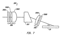
- Figure 7 discloses an alternate laser energy directional modification assembly 392 that includes an input lens assembly 396, a wedge prism 397, and an output lens assembly 398.
- the wedge prism 397 serves to change the direction of the laser energy.
- the wedge prism 397 provides higher laser energy throughput than is available from a mirror 204.
- the laser energy is directed toward the receiving surface at a non-orthogonal angle.
- Prior art devices use a mirror to direct the laser energy to the surface in such a manner that the laser energy impinges upon the surface in an orthogonal manner. In this configuration, reflective laser energy disrupts the incoming laser energy. In addition, a plume and spatter is produced which must be removed by conventional techniques to prevent damage to the optics.
- the laser energy is impinged upon the surface 20 to be welded at an angle of say 45°, as shown in Figure 7, then reflective laser energy does not disrupt the incoming laser energy.
- Figure 9 illustrates a rotating welding head 322A that may be used with the apparatus of Figure 8.
- the figure illustrates a fixed fiber optic cable 343 positioned within a fixed interior tube 402.
- the rotating sleeve 324A rotates about the fixed interior tube 402.
- the rotating sleeve 324A includes a gas conduit 389.
- the rotating sleeve 324A includes a machined groove 386A (shown in phantom) that serves as the filler passage.
- the filler passage 386A runs the length of the rotating sleeve 324A.
- the filler passage may also be formed as a small tube running the length of the rotating sleeve 324A.
- the laser energy directional modification assembly 392 rotates with the rotating sleeve 324A and receives the laser energy from the stationary fiber optic cable 343.
- the examples of Figures 5-11 have been implemented using a Hobart 2400 Watt laser with a 1064 nanometer wavelength, from Hobart Laser Products, Inc., Livermore, California.
- the optical cable used is preferably formed of fused silica fiber encased in a metallic, flexible sheath.
- the fiber is coated with a reflective coating to prevent surface absorption of the laser beam and to enhance transmission.
- the optical cable may have a 600-800 micron spot size.
- the rotating sleeve 324 may be formed of stainless steel or a flexible metallic tubing.
- the rotating sleeve 324 has been implemented with a circular sleeve with an outer diameter of 1.27 cm [0.5 inches] and an inner diameter of 9.40 mm [0.370 inches].
- the filler passage 386 size is governed by the filler wire size.
- the filler passage 386 size is preferably several hundredths of a millimeter [a few thousandth of an inch] greater than the diameter of the wire. Wire diameters commonly utilized include 0.5 mm [0.20 inches], 0.6 mm [.025 inches], 0.75 mm [.030 inches], and 0.89 mm [.035 inches].
- the rotating apparatus drive mechanism 25 is preferably a stepper motor.
- the drive mechanism 325 is coupled to the rotating sleeve 324 and the filler assembly 326 by conventional techniques, such as gears or belts.
- the axial drive system 350 has been implemented using a stepper motor mounted on a shaft 351. Horizontal or planar motion may be obtained by manually positioning the shaft 351. In the alternative, the shaft 351 may be positioned in a motorized planar movement device (not shown), that allows the rotating apparatus 320 to be positioned at any selected tube 20.
- the filler metal delivery system 330 may be of the type used in existing welders.
- the invention has been implemented using an ASTRO ARC wire feeder, from ASTRO ARC, Inc., Sun Valley, California.
- the laser energy directional modification assembly 392 of Figure 7 has been implemented using standard lenses.
- the input lens assembly 396 collimates the laser light beam to form a collimated beam.
- the input lens assembly 396 includes a window lens 396A, a -20mm f.l. lens 396B, and a +10 mm f.l. lens 396C.
- the wedge prism 397 bends the collimated beam (from 10 to 60 degrees, preferably from 20 to 45 degrees, and most preferably approximately 30 degrees) to form a bent and collimated beam.
- the bent and collimated beam is conveyed to the output lens assembly 398, which includes a +20mm f.l. lens 398A and a window lens 398B.
- the output lens assembly 398 forms a focused and collimated beam of a small diameter with very high energy density.
- the beam provides maximum thermal energy at the point of welding, thereby melting the filler material and a portion of the base material in a controlled manner.
- the laser energy directional modification assembly 392 has been used at 2400 Watts continuous output, without failure. Prior art devices using mirrors have generally been limited to laser energies of 1000 Watts.
- the fixed interior tube 402 of Figure 9 is preferably formed of stainless steel.
- the rotating tube 324A of Figure 9 is preferably formed of stainless steel. Commercially available Nylon or Teflon® bearings are used between the fixed interior tube 402 and the rotating tube 324A.
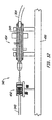
- Figures 12 to 16 illustrate an optical coupler 342 that may be used in a laser welding apparatus in accordance with the invention.
- Figure 15 illustrates an embodiment of one feature of the optical coupler 342.
- the optical coupler 342 provides an interface between the fixed fiber optic cable 343 and the rotating sleeve 324, which encases a rotating fiber optic cable 340.
- the optical coupler 342 includes a base plate 450 that supports a fixed optical assembly 452 and a rotating cable interface assembly 454.
- the optical assembly 452 preferably includes positioning devices to provide independent axial and concentric alignment.
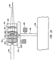
- Figure 13 illustrates an axial mounting stage 474 for the optical socket assembly 460.
- the axial mounting stage 474 can be positioned with an axial alignment device 476 along the axis defined by the rotating fiber optic cable 340 and the fixed fiber optic cable 343.
- the axial alignment device 476 may be implemented as a threaded screw that adjusts an axial gear, or an analogous structure, many of which are known to those skilled in the art.
- Figure 13 also illustrates a transverse support 478 that can be positioned along an axis that is transverse to the axis defined by the rotating fiber optic cable 340 and the fixed fiber optic cable 343.
- a transverse alignment device 480 may be used to reposition the axial mounting stage 474 in the specified transverse (or concentric) direction.
- the transverse alignment device 480 may be implemented as a threaded screw that adjusts an axial gear, or an equivalent structure.
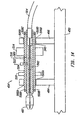
- the rotating cable interface assembly 454 of apparatus is illustrated.
- the focused and collimated laser beam 482 produced by the fixed fiber optical assembly 452 is received by an interface receiving structure 487.
- a rotating fiber optic cable 340 Positioned within the interface receiving structure 487 and along the axis of the rotating cable interface assembly 454 is a rotating fiber optic cable 340.
- the rotating fiber optic cable 340 consists of a fused silica glass monofilament fiber with a silica glass cladding.
- the rotating sleeve may 324 include a polymer coating, buffer layers, and a protective metallic sheath including a polyethylene cover.
- the rotating cable interface assembly 454 includes a first interface support 484 and a second interface support 486, both of which are connected to base plate 450.
- the first interface support 484 and the second interface support 486 are used to support a mounting sleeve 500, which is surrounded by an alignment tube 504.
- the alignment tube 504 rotates in a set of bearings 506A and 506B respectively positioned in the interface supports 484 and 486.
- the alignment tube 504 may be driven by a gear 510.
- the position of the alignment tube 504 may be adjusted with a set of alignment screws 508A, 508B, 508C, and 508D. In one embodiment of the invention, four alignment screws 508 are provided at each end of the alignment tube 504.
- the alignment tube 504 is used to align the position of the optic fiber 340 with the incoming laser beam 482.
- the accuracy of the alignment is measured through the use of a monitor cavity 502 positioned within the mounting sleeve 500.
- a photocell 512 is optically connected to the monitor cavity 502.
- the photocell generates a voltage proportional to the amount of light in the cavity 502.
- the voltage (output) signal is conveyed to a slip ring 514 over a conductor 516.
- the slip ring is connected to a stationary piece of equipment (not shown), such as a digital volt meter, which provides a signal corresponding to the output of the photocell 512.
- the alignment screws 508 are adjusted to achieve this result.
- the axial alignment device 476 and transverse alignment device 480 may be used for course adjustments.
- FIG. 15 illustrates an alternate embodiment of a rotating cable interface assembly 454A which may be used in a laser welding apparatus in accordance with the invention.
- This embodiment of the invention includes a safety fiber optic 520.
- a safety fiber optic 520 monitors reflected light at a welding point. The reflected light is transmitted through the safety fiber 520 to a photocell detector, where it is analyzed. If the monitored light level is inconsistent with normal operation, the laser energy is discontinued. The use of this monitoring device is important to minimize optical damage due to reflected light energy within the optical components.
- Figure 15 illustrates that the rotating sleeve 324 may be encased in a non-rotating protective sheath 530.
- Bearings 532 may be positioned between the rotating sleeve 324 and the non-rotating protective sheath 530.
- the sheath 530 provides a protective cover to prevent damage and abrasion to the rotating sleeve 324 and the rotating fiber optic cable 340 positioned therein.
- the sheath 530 also permits an axial drive mechanism to directly grip the sheath 530 so that the rotating fiber optic cable 340 can be positioned at a desired axial location.
- Figure 16 illustrates a rotating welding head 322 encased within a non-rotating protective sheath 530.
- Bearings 532 are preferably positioned between the rotating welding head body 380 and the non-rotating protective sheath 530.
- the device provides for precision alignment between the fixed fiber optic cable 343 and the rotating fiber optic cable 340.
- This feature is extremely important in view of the fact that optical fibers are never identical, and therefore have an inherent optical misalignment.
- the invention accommodates this problem.
- the invention is also advantageous in that it incorporates a safety fiber optic 520 in a rotating apparatus.
- the apparatus of the invention has been used at rotational speeds in excess of 100 RPMs.
Landscapes
- Physics & Mathematics (AREA)
- Optics & Photonics (AREA)
- Engineering & Computer Science (AREA)
- Mechanical Engineering (AREA)
- Plasma & Fusion (AREA)
- High Energy & Nuclear Physics (AREA)
- Thermal Sciences (AREA)
- General Engineering & Computer Science (AREA)
- Chemical & Material Sciences (AREA)
- Chemical Kinetics & Catalysis (AREA)
- General Chemical & Material Sciences (AREA)
- Oil, Petroleum & Natural Gas (AREA)
- Laser Beam Processing (AREA)
- Mechanical Coupling Of Light Guides (AREA)
- Optical Couplings Of Light Guides (AREA)
- Lining Or Joining Of Plastics Or The Like (AREA)
- Manufacture Of Macromolecular Shaped Articles (AREA)
- Pressure Welding/Diffusion-Bonding (AREA)
- Optical Fibers, Optical Fiber Cores, And Optical Fiber Bundles (AREA)
Claims (12)
- Laserschweißvorrichtung zum Schweißen der Innenfläche eines Rohres, umfassend:einen stationären Laser (334) zum Erzeugen von Lichtenergie; eine rotierende Hülse (324), die ein Lichtleitfaserkabel (340) umschließt;einen optischen Koppler (342), der zwischen dem stationären Laser (334) und der rotierenden Hülse (324) angeordnet ist; dadurch gekennzeichnet, daßder optische Koppler eine unbewegliche optische Baugruppe, um Lichtenergie vom stationaren Laser zu empfangen und gerichtete und fokussierte Lichtenergie zu erzeugen, und eine rotierende Kabelschnittstellenbaugruppe (454) enthält, um die gerichtete und fokussierte Lichtenergie zu empfangen und mit dieser das Lichtleitfaserkabel der rotierenden Hülse (324) zu beaufschlagen, wobei die rotierende Kabelschnittstellenbaugruppe (454) eine Photozelle (512) zum Messen der Ausrichtung zwischen der unbeweglichen optischen Baugruppe und der rotierenden Kabelschnittstellenbaugruppe (454) enthält.
- Laserschweißvorrichtung nach Anspruch 1, bei der die rotierende Kabelschnittstellenbaugruppe (454) ein Positionseinstellungsmittel enthält, um die gerichtete and fokussierte Lichtenergie auf das Lichtleitfaserkabel auszurichten.
- Laserschweißvorrichtung nach Anspruch 1 oder 2, bei der die rotierende Kabelschnittstellenbaugruppe (454) eine Kammer enthält, die einen Monitorhohlraum (502) definiert.
- Laserschweißvorrichtung nach Anspruch 3, bei der die Photozelle (512) mit dem Monitorhohlraum (502) optisch verbunden ist, um das von einem Signal emittierte Licht zu empfangen, das die Ausrichtung zwischen der unbeweglichen optischen Baugruppe und dem Lichtleitfaserkabel (340) der rotierenden Hülse (324) anzeigt.
- Laserschweißvorrichtung nach Anspruch 4, die einen Gleitring (516) enthält, der mit der Photozelle (512) elektrisch verbunden ist, um das Ausgangssignal zu empfangen.
- Laserschweißvorrichtung nach Anspruch 3 oder 4, die ferner enthält:eine Sicherheitsfaseroptik (520), die innerhalb der Monitorhülse angeordnet ist; undeine Sicherheitsfaseroptik-Photozelle (522), die mit der Sicherheitsfaseroptik (520) optisch verbunden ist.
- Laserschweißvorrichtung nach irgendeinem der vorangehenden Ansprüche, die ferner einen nicht-rotierenden Schutzmantel (530) enthält, der um die rotierende Hülse (324) angeordnet ist.
- Laserschweißvorrichtung nach irgendeinem der Ansprüche 1 bis 7, bei der die rotierende Kabelschnittstellenbaugruppe (454) ferner umfaßt:Positionierungsvorrichtungen zum Ändern des Ortes, an dem die fokussierte Lichtenergie von der unbeweglichen optischen Baugruppe die rotierende Kabelschnittstellenbaugruppe kreuzt.
- Laserschweißvorrichtung nach Anspruch 8, bei der die Positionierungsvorrichtungen enthalten:eine axiale Montagebühne (474) zum Halten der unbeweglichen optische Baugruppe; undeine axiale Ausrichtungsvorrichtung (476) zum axialen Positionieren der axialen Montagebühne.
- Laserschweißvorrichtung nach Anspruch 9, bei der die Positionierungsvorrichtungen enthalten:einen Querträger (478) für die axiale Montagebühne; undeine Querausrichtungsvorrichtung (480), um eine konzentrische Positionierung der axialen Montagebühne zu bewerkstelligen.
- Laserschweißvorrichtung nach irgendeinem der Ansprüche 8 bis 10, bei der die rotierende Kabelschnittstellenbaugruppe enthält:einen ersten Schnittstellenträger (484) zum Montieren eines ersten Lagers (506A);einen zweiten Schnittstellenträger (486) zum Montieren eines zweiten Lagers (506B);ein Ausrichtungsrohr (504), das innerhalb des ersten Lagers und des zweiten Lagers angeordnet ist, undeine Monitorhülse (500), die innerhalb des Ausrichtungsrohres angeordnet ist, wobei die Monitorhülse das Lichtleitfaserkabel der rotierenden Hülse unterstützt.
- Laserschweißvorrichtung nach irgendeinem der Ansprüche 8 bis 11, bei der die Positionierungsvorrichtungen einen Satz Ausrichtungsschrauben (508A-508D) enthalten, die innerhalb des Ausrichtungsrohres angeordnet sind, um die konzentrische Position der Monitorhülse (500) einzustellen.
Applications Claiming Priority (3)
| Application Number | Priority Date | Filing Date | Title |
|---|---|---|---|
| US410714 | 1995-03-27 | ||
| US08/410,714 US5653897A (en) | 1993-02-17 | 1995-03-27 | Rotating fiber optic coupler for high power laser welding applications |
| PCT/US1996/004429 WO1996030156A1 (en) | 1995-03-27 | 1996-03-27 | Rotating fiber optic coupler for high power laser welding applications |
Publications (3)
| Publication Number | Publication Date |
|---|---|
| EP0817697A1 EP0817697A1 (de) | 1998-01-14 |
| EP0817697A4 EP0817697A4 (de) | 1998-09-30 |
| EP0817697B1 true EP0817697B1 (de) | 2003-08-06 |
Family
ID=23625927
Family Applications (1)
| Application Number | Title | Priority Date | Filing Date |
|---|---|---|---|
| EP96910684A Expired - Lifetime EP0817697B1 (de) | 1995-03-27 | 1996-03-27 | Rotierender faseroptischer koppler für die anpassungen des hochleistungslaserschweissens |
Country Status (12)
| Country | Link |
|---|---|
| US (1) | US5653897A (de) |
| EP (1) | EP0817697B1 (de) |
| JP (1) | JP3862239B2 (de) |
| KR (1) | KR100407041B1 (de) |
| AT (1) | ATE246566T1 (de) |
| AU (1) | AU5381496A (de) |
| CA (1) | CA2213412A1 (de) |
| DE (1) | DE69629362T2 (de) |
| DK (1) | DK0817697T3 (de) |
| ES (1) | ES2202434T3 (de) |
| PT (1) | PT817697E (de) |
| WO (1) | WO1996030156A1 (de) |
Cited By (2)
| Publication number | Priority date | Publication date | Assignee | Title |
|---|---|---|---|---|
| US11285563B2 (en) | 2017-10-20 | 2022-03-29 | Branson Ultrasonics Corporation | Fiber feedback |
| US11305380B2 (en) | 2018-01-22 | 2022-04-19 | Branson Ultrasonics Corporation | Method of determining intensity of laser light delivered to a weld area by laser delivery bundles |
Families Citing this family (28)
| Publication number | Priority date | Publication date | Assignee | Title |
|---|---|---|---|---|
| EP2263822A3 (de) * | 1997-03-28 | 2014-10-01 | Nippon Steel & Sumitomo Metal Corporation | Verfahren und Vorrichtung zum Stumpfschweißen von warmgewalzten Blöcken mit einem Laserstrahl |
| JP2002525649A (ja) * | 1998-09-11 | 2002-08-13 | コーニング インコーポレイテッド | ファイバ結合可変光減衰器 |
| EP1137896B1 (de) | 1998-12-09 | 2003-07-23 | Steris Inc. | Faseroptische zusatzlampe für deckenoperationsleuchte mit optischem gelenk und handobjektivlinse |
| US6486432B1 (en) * | 1999-11-23 | 2002-11-26 | Spirex | Method and laser cladding of plasticating barrels |
| EP1215033A1 (de) * | 2000-12-12 | 2002-06-19 | Paul N. Colby | Verfahren zur Laserplattierung von Plastifizierzylindern |
| US7088880B1 (en) * | 2003-12-24 | 2006-08-08 | Lockheed Martin Corporation | Optical fiber coupling and inline fault monitor device and method |
| US7728967B2 (en) * | 2005-07-07 | 2010-06-01 | Kabushiki Kaisha Toshiba | Laser-based maintenance apparatus |
| US20070056939A1 (en) * | 2005-09-09 | 2007-03-15 | Colby Paul T | Method for laser cladding of tubes |
| KR100777649B1 (ko) | 2007-03-12 | 2007-11-21 | 주식회사 쿠키혼 | 가공 대상물의 내면에 패턴을 형성하는 레이저 장치 |
| KR100777652B1 (ko) | 2007-03-19 | 2007-11-21 | 주식회사 쿠키혼 | 가공 대상물의 내면에 패턴을 형성하는 레이저 장치 |
| JP5011072B2 (ja) * | 2007-11-21 | 2012-08-29 | 株式会社ディスコ | レーザー加工装置 |
| US20090291197A1 (en) | 2008-05-21 | 2009-11-26 | Fraunhofer Usa | Laser cladding of tubes |
| JP5632924B2 (ja) * | 2009-11-03 | 2014-11-26 | ザ セクレタリー,デパートメント オブ アトミック エナジー,ガヴァメント,オブ インディア | レーザ溶接によって結合されたニオブ部品を備えるニオブベース超伝導無線周波(scrf)キャビティおよびその製造方法並びに製造装置 |
| US9168613B2 (en) | 2010-10-22 | 2015-10-27 | Paul T. Colby | Vertical laser cladding system |
| US8927897B2 (en) | 2010-11-17 | 2015-01-06 | Rolls-Royce Corporation | Laser maintenance tool |
| WO2012116155A1 (en) * | 2011-02-24 | 2012-08-30 | Foro Energy, Inc. | Electric motor for laser-mechanical drilling |
| JP5710407B2 (ja) * | 2011-07-15 | 2015-04-30 | 株式会社東芝 | レーザ溶接装置 |
| US9573215B2 (en) | 2012-02-10 | 2017-02-21 | Illinois Tool Works Inc. | Sound-based weld travel speed sensing system and method |
| WO2014151927A1 (en) * | 2013-03-14 | 2014-09-25 | Ipg Photonics Corporation | Universal fiber optic connector |
| US10328513B2 (en) | 2013-05-31 | 2019-06-25 | General Electric Company | Welding process, welding system, and welded article |
| GB2543355B (en) * | 2015-10-16 | 2020-06-24 | Rolls Royce Power Eng Plc | Pressure vessel |
| CN108772627B (zh) * | 2018-06-07 | 2022-01-28 | 深圳市华天世纪激光科技有限公司 | 一种用于汽车上电机铜环端子的激光焊接设备 |
| CN109913916B (zh) * | 2019-02-21 | 2021-05-25 | 江苏大学 | 一种制备管道内壁超疏水结构的装置及方法 |
| DE202019103788U1 (de) | 2019-07-10 | 2019-10-24 | Bios S.R.L. | Rotierbares Verbindungsstück für eine Glasfaser |
| DE102020128145A1 (de) * | 2020-10-26 | 2022-04-28 | Inprocoat Holding Gmbh | Rohrabschnitt und verfahren zur herstellung einer innenbeschichtung für einen solchen |
| CN112899679A (zh) * | 2021-03-19 | 2021-06-04 | 西安科技大学 | 一种旋转激光熔覆系统及其熔覆方法 |
| US20240308000A1 (en) * | 2023-03-14 | 2024-09-19 | Saudi Arabian Oil Company | Cladding process for in-situ pipes integrity |
| CN119501298A (zh) * | 2025-01-20 | 2025-02-25 | 常州市蓝托金属制品有限公司 | 一种航空铝合金滑轨套筒的激光焊接系统及焊接方法 |
Citations (1)
| Publication number | Priority date | Publication date | Assignee | Title |
|---|---|---|---|---|
| WO1994019141A1 (en) * | 1993-02-17 | 1994-09-01 | Electric Power Research Institute, Inc. | Method and apparatus for repairing damaged tubes |
Family Cites Families (45)
| Publication number | Priority date | Publication date | Assignee | Title |
|---|---|---|---|---|
| US3463591A (en) * | 1962-10-10 | 1969-08-26 | Lear Siegler Inc | Laser spectroscopy |
| US3310423A (en) * | 1963-08-27 | 1967-03-21 | Metco Inc | Flame spraying employing laser heating |
| US3265584A (en) * | 1963-11-13 | 1966-08-09 | Richard C Cooper | Nuclear reactor viewing system |
| US3943324A (en) * | 1970-12-14 | 1976-03-09 | Arthur D. Little, Inc. | Apparatus for forming refractory tubing |
| US3762938A (en) * | 1971-03-29 | 1973-10-02 | Dow Chemical Co | Deposition of thin metal films |
| US3772496A (en) * | 1971-10-26 | 1973-11-13 | Western Electric Co | Methods of forming a conductive path using an oxygen plasma to reduce reflectivity prior to laser machining |
| US3947653A (en) * | 1973-10-24 | 1976-03-30 | Sirius Corporation | Method of spray coating using laser-energy beam |
| US4117302A (en) * | 1974-03-04 | 1978-09-26 | Caterpillar Tractor Co. | Method for fusibly bonding a coating material to a metal article |
| GB1500964A (en) * | 1974-04-11 | 1978-02-15 | Saipem Spa | Apparatus for welding pipelines |
| GB1507204A (en) * | 1974-07-12 | 1978-04-12 | Caterpillar Tractor Co | Apparatus for heat treating an internal bore in a workpiece |
| US3952180A (en) * | 1974-12-04 | 1976-04-20 | Avco Everett Research Laboratory, Inc. | Cladding |
| US4029932A (en) * | 1975-05-05 | 1977-06-14 | Holobeam, Inc. | Lined pipe, and method and apparatus for making same |
| CA1095387A (en) * | 1976-02-17 | 1981-02-10 | Conrad M. Banas | Skin melting |
| US4072147A (en) * | 1976-03-04 | 1978-02-07 | American Cystoscope Makers Inc. | Radiation endoscope |
| FR2348486A1 (fr) * | 1976-04-15 | 1977-11-10 | Commissariat Energie Atomique | Procede et dispositif d'analyse d'echantillon par spectrographie d'emission utilisant un faisceau laser |
| US4157923A (en) * | 1976-09-13 | 1979-06-12 | Ford Motor Company | Surface alloying and heat treating processes |
| US4207874A (en) * | 1978-03-27 | 1980-06-17 | Choy Daniel S J | Laser tunnelling device |
| IT1172891B (it) * | 1978-07-04 | 1987-06-18 | Fiat Spa | Procedimento per rivestire con materiale antiusura una superficie metallica |
| US4178512A (en) * | 1978-07-21 | 1979-12-11 | Impulsphysik Gmbh | Deepwater in-situ fluorometer |
| US4212900A (en) * | 1978-08-14 | 1980-07-15 | Serlin Richard A | Surface alloying method and apparatus using high energy beam |
| GB2052566B (en) * | 1979-03-30 | 1982-12-15 | Rolls Royce | Laser aplication of hard surface alloy |
| US4242981A (en) * | 1979-05-25 | 1981-01-06 | Bernard Philippe G | Apparatus for rebuilding cylindrical objects |
| US4323756A (en) * | 1979-10-29 | 1982-04-06 | United Technologies Corporation | Method for fabricating articles by sequential layer deposition |
| IT1130474B (it) * | 1980-05-28 | 1986-06-11 | Fiat Auto Spa | Procedimento e dispositivo per l ispezione ed il controllo della superficie interna di un pezzo cilindrico cavo che ha subito una lavorazione meccanica |
| US4495255A (en) * | 1980-10-30 | 1985-01-22 | At&T Technologies, Inc. | Laser surface alloying |
| US4365136A (en) * | 1981-02-23 | 1982-12-21 | Hydril Company | Zone refinement of inertia welded tubulars to impart improved corrosion resistance |
| DE3224810A1 (de) * | 1982-07-02 | 1984-01-05 | Siemens AG, 1000 Berlin und 8000 München | Verfahren zur erzeugung harter, verschleissfester randschichten auf einem metallischen werkstoff |
| US4543270A (en) * | 1984-06-20 | 1985-09-24 | Gould Inc. | Method for depositing a micron-size metallic film on a transparent substrate utilizing a visible laser |
| US4737011A (en) * | 1984-07-13 | 1988-04-12 | Dainichi-Nippon Cables Ltd. | Connector for high energy beam |
| US4743733A (en) * | 1984-10-01 | 1988-05-10 | General Electric Company | Method and apparatus for repairing metal in an article |
| US4746540A (en) * | 1985-08-13 | 1988-05-24 | Toyota Jidosha Kabushiki Kaisha | Method for forming alloy layer upon aluminum alloy substrate by irradiating with a CO2 laser, on substrate surface, alloy powder containing substance for alloying and silicon or bismuth |
| US4827098A (en) * | 1987-07-06 | 1989-05-02 | Westinghouse Electric Corp. | Flexible laser welding head for sleeve-to-tube welding |
| JPS6462290A (en) * | 1987-08-31 | 1989-03-08 | Mitsubishi Heavy Ind Ltd | Repairing device for pipe inner peripheral face |
| US5177808A (en) * | 1989-11-02 | 1993-01-05 | Mitsubishi Jukogyo Kabushiki Kaisha | Optical energy beam transmission path structure |
| FR2662507B1 (fr) * | 1990-05-22 | 1992-07-24 | Thomson Csf | Joint tournant mixte hyperfrequence et optique. |
| US5196671A (en) * | 1990-08-17 | 1993-03-23 | Siemens Aktiengesellschaft | Device and process for the laser welding of a tube |
| US5151962A (en) * | 1991-05-20 | 1992-09-29 | Fiber Delivery Concepts, Inc. | Fiber optic cable assemblies for laser delivery systems |
| US5315684A (en) * | 1991-06-12 | 1994-05-24 | John Mezzalingua Assoc. Inc. | Fiber optic cable end connector |
| US5170452A (en) * | 1991-09-09 | 1992-12-08 | Porta Systems Corp. | Fiber optic plug connector and adapter therefor |
| US5157745A (en) * | 1991-09-16 | 1992-10-20 | The United States Of America As Represented By The Secretary Of The Navy | Multi-channel fiber optic rotary joint for single-mode fiber |
| US5271076A (en) * | 1992-10-05 | 1993-12-14 | The United States Of America As Represented By The Secretary Of The Navy | Method providing optimum optical trains alignment in a passive multi-channel fiber optic rotary joint |
| US5359172A (en) * | 1992-12-30 | 1994-10-25 | Westinghouse Electric Corporation | Direct tube repair by laser welding |
| US5514849A (en) * | 1993-02-17 | 1996-05-07 | Electric Power Research Institute, Inc. | Rotating apparatus for repairing damaged tubes |
| US5491317A (en) * | 1993-09-13 | 1996-02-13 | Westinghouse Electric Corporation | System and method for laser welding an inner surface of a tubular member |
| US5371767A (en) * | 1994-02-01 | 1994-12-06 | Westinghouse Electric Corporation | System and method for laser welding an inner surface of a small diameter tubular member |
-
1995
- 1995-03-27 US US08/410,714 patent/US5653897A/en not_active Expired - Lifetime
-
1996
- 1996-03-27 EP EP96910684A patent/EP0817697B1/de not_active Expired - Lifetime
- 1996-03-27 CA CA002213412A patent/CA2213412A1/en not_active Abandoned
- 1996-03-27 DK DK96910684T patent/DK0817697T3/da active
- 1996-03-27 JP JP52973296A patent/JP3862239B2/ja not_active Expired - Fee Related
- 1996-03-27 WO PCT/US1996/004429 patent/WO1996030156A1/en not_active Ceased
- 1996-03-27 ES ES96910684T patent/ES2202434T3/es not_active Expired - Lifetime
- 1996-03-27 DE DE69629362T patent/DE69629362T2/de not_active Expired - Fee Related
- 1996-03-27 PT PT96910684T patent/PT817697E/pt unknown
- 1996-03-27 AT AT96910684T patent/ATE246566T1/de not_active IP Right Cessation
- 1996-03-27 AU AU53814/96A patent/AU5381496A/en not_active Abandoned
- 1996-03-27 KR KR1019970706714A patent/KR100407041B1/ko not_active Expired - Fee Related
Patent Citations (1)
| Publication number | Priority date | Publication date | Assignee | Title |
|---|---|---|---|---|
| WO1994019141A1 (en) * | 1993-02-17 | 1994-09-01 | Electric Power Research Institute, Inc. | Method and apparatus for repairing damaged tubes |
Cited By (2)
| Publication number | Priority date | Publication date | Assignee | Title |
|---|---|---|---|---|
| US11285563B2 (en) | 2017-10-20 | 2022-03-29 | Branson Ultrasonics Corporation | Fiber feedback |
| US11305380B2 (en) | 2018-01-22 | 2022-04-19 | Branson Ultrasonics Corporation | Method of determining intensity of laser light delivered to a weld area by laser delivery bundles |
Also Published As
| Publication number | Publication date |
|---|---|
| DE69629362D1 (de) | 2003-09-11 |
| EP0817697A1 (de) | 1998-01-14 |
| DK0817697T3 (da) | 2003-11-24 |
| KR19980703310A (ko) | 1998-10-15 |
| AU5381496A (en) | 1996-10-16 |
| CA2213412A1 (en) | 1996-10-03 |
| KR100407041B1 (ko) | 2004-02-18 |
| PT817697E (pt) | 2003-12-31 |
| DE69629362T2 (de) | 2004-02-19 |
| ES2202434T3 (es) | 2004-04-01 |
| US5653897A (en) | 1997-08-05 |
| WO1996030156A1 (en) | 1996-10-03 |
| ATE246566T1 (de) | 2003-08-15 |
| EP0817697A4 (de) | 1998-09-30 |
| JPH11502774A (ja) | 1999-03-09 |
| JP3862239B2 (ja) | 2006-12-27 |
Similar Documents
| Publication | Publication Date | Title |
|---|---|---|
| EP0817697B1 (de) | Rotierender faseroptischer koppler für die anpassungen des hochleistungslaserschweissens | |
| EP0684887B1 (de) | Verfahren und vorrichtung zum reparieren beschädigter rohre | |
| US5514849A (en) | Rotating apparatus for repairing damaged tubes | |
| US5977513A (en) | Apparatus and method for centering a laser welding probe within a tube using gas pressure | |
| US5667706A (en) | Apparatus and method for laser welding the inner surface of a tube | |
| US5593605A (en) | Internal laser welder for pipeline | |
| EP1691949B1 (de) | Orbitalschweissvorrichtung für den rohrleitungsbau | |
| DE68904049T2 (de) | Schweissverfahren und schweissvorrichtung, um aus der entfernung eine muffe in ein rohr, insbesondere innerhalb eines dampferzeugers eines kernkraftwerkes, einzuschweissen. | |
| US5491317A (en) | System and method for laser welding an inner surface of a tubular member | |
| EP0665080B1 (de) | Anordnung und Verfahren zum Laserschweissen an der Innenwandung von Rohren kleinen Durchmessers | |
| EP0465106B1 (de) | System und Verfahren zum Laserschweissen der Innenoberfläche einer Leitung | |
| DE69003043T2 (de) | Vorrichtung zum Laserschweissen im Inneren eines Rohrelementes. | |
| EP0515173B1 (de) | System und Verfahren zum Einsatzschweissen der inneren Oberfläche eines Rohres | |
| WO1997009149A1 (en) | Method for in-situ component upgrade |
Legal Events
| Date | Code | Title | Description |
|---|---|---|---|
| PUAI | Public reference made under article 153(3) epc to a published international application that has entered the european phase |
Free format text: ORIGINAL CODE: 0009012 |
|
| 17P | Request for examination filed |
Effective date: 19971016 |
|
| AK | Designated contracting states |
Kind code of ref document: A1 Designated state(s): AT BE CH DE DK ES FI FR GB GR IE IT LI LU MC NL PT SE |
|
| A4 | Supplementary search report drawn up and despatched |
Effective date: 19980810 |
|
| AK | Designated contracting states |
Kind code of ref document: A4 Designated state(s): AT BE CH DE DK ES FI FR GB GR IE IT LI LU MC NL PT SE |
|
| 17Q | First examination report despatched |
Effective date: 20020425 |
|
| GRAH | Despatch of communication of intention to grant a patent |
Free format text: ORIGINAL CODE: EPIDOS IGRA |
|
| GRAH | Despatch of communication of intention to grant a patent |
Free format text: ORIGINAL CODE: EPIDOS IGRA |
|
| GRAA | (expected) grant |
Free format text: ORIGINAL CODE: 0009210 |
|
| AK | Designated contracting states |
Designated state(s): AT BE CH DE DK ES FI FR GB GR IE IT LI LU MC NL PT SE |
|
| REG | Reference to a national code |
Ref country code: GB Ref legal event code: FG4D |
|
| REG | Reference to a national code |
Ref country code: CH Ref legal event code: EP |
|
| REG | Reference to a national code |
Ref country code: IE Ref legal event code: FG4D |
|
| REF | Corresponds to: |
Ref document number: 69629362 Country of ref document: DE Date of ref document: 20030911 Kind code of ref document: P |
|
| REG | Reference to a national code |
Ref country code: CH Ref legal event code: NV Representative=s name: ARNOLD & SIEDSMA AG |
|
| REG | Reference to a national code |
Ref country code: GR Ref legal event code: EP Ref document number: 20030404143 Country of ref document: GR |
|
| REG | Reference to a national code |
Ref country code: DK Ref legal event code: T3 |
|
| REG | Reference to a national code |
Ref country code: SE Ref legal event code: TRGR |
|
| PG25 | Lapsed in a contracting state [announced via postgrant information from national office to epo] |
Ref country code: LU Free format text: LAPSE BECAUSE OF NON-PAYMENT OF DUE FEES Effective date: 20040327 Ref country code: GB Free format text: LAPSE BECAUSE OF NON-PAYMENT OF DUE FEES Effective date: 20040327 Ref country code: FI Free format text: LAPSE BECAUSE OF NON-PAYMENT OF DUE FEES Effective date: 20040327 Ref country code: AT Free format text: LAPSE BECAUSE OF NON-PAYMENT OF DUE FEES Effective date: 20040327 |
|
| PG25 | Lapsed in a contracting state [announced via postgrant information from national office to epo] |
Ref country code: SE Free format text: LAPSE BECAUSE OF NON-PAYMENT OF DUE FEES Effective date: 20040328 |
|
| PG25 | Lapsed in a contracting state [announced via postgrant information from national office to epo] |
Ref country code: IE Free format text: LAPSE BECAUSE OF NON-PAYMENT OF DUE FEES Effective date: 20040329 Ref country code: ES Free format text: LAPSE BECAUSE OF NON-PAYMENT OF DUE FEES Effective date: 20040329 |
|
| PG25 | Lapsed in a contracting state [announced via postgrant information from national office to epo] |
Ref country code: MC Free format text: LAPSE BECAUSE OF NON-PAYMENT OF DUE FEES Effective date: 20040331 Ref country code: LI Free format text: LAPSE BECAUSE OF NON-PAYMENT OF DUE FEES Effective date: 20040331 Ref country code: DK Free format text: LAPSE BECAUSE OF NON-PAYMENT OF DUE FEES Effective date: 20040331 Ref country code: CH Free format text: LAPSE BECAUSE OF NON-PAYMENT OF DUE FEES Effective date: 20040331 Ref country code: BE Free format text: LAPSE BECAUSE OF NON-PAYMENT OF DUE FEES Effective date: 20040331 |
|
| REG | Reference to a national code |
Ref country code: ES Ref legal event code: FG2A Ref document number: 2202434 Country of ref document: ES Kind code of ref document: T3 |
|
| ET | Fr: translation filed | ||
| PLBE | No opposition filed within time limit |
Free format text: ORIGINAL CODE: 0009261 |
|
| STAA | Information on the status of an ep patent application or granted ep patent |
Free format text: STATUS: NO OPPOSITION FILED WITHIN TIME LIMIT |
|
| 26N | No opposition filed |
Effective date: 20040507 |
|
| BERE | Be: lapsed |
Owner name: *ELECTRIC POWER RESEARCH INSTITUTE INC. Effective date: 20040331 |
|
| PG25 | Lapsed in a contracting state [announced via postgrant information from national office to epo] |
Ref country code: NL Free format text: LAPSE BECAUSE OF NON-PAYMENT OF DUE FEES Effective date: 20041001 Ref country code: DE Free format text: LAPSE BECAUSE OF NON-PAYMENT OF DUE FEES Effective date: 20041001 |
|
| PG25 | Lapsed in a contracting state [announced via postgrant information from national office to epo] |
Ref country code: GR Free format text: LAPSE BECAUSE OF NON-PAYMENT OF DUE FEES Effective date: 20041006 |
|
| EUG | Se: european patent has lapsed | ||
| REG | Reference to a national code |
Ref country code: CH Ref legal event code: PL |
|
| GBPC | Gb: european patent ceased through non-payment of renewal fee |
Effective date: 20040327 |
|
| PG25 | Lapsed in a contracting state [announced via postgrant information from national office to epo] |
Ref country code: FR Free format text: LAPSE BECAUSE OF NON-PAYMENT OF DUE FEES Effective date: 20041130 |
|
| NLV4 | Nl: lapsed or anulled due to non-payment of the annual fee |
Effective date: 20041001 |
|
| PG25 | Lapsed in a contracting state [announced via postgrant information from national office to epo] |
Ref country code: PT Free format text: LAPSE BECAUSE OF NON-PAYMENT OF DUE FEES Effective date: 20041227 |
|
| REG | Reference to a national code |
Ref country code: FR Ref legal event code: ST |
|
| REG | Reference to a national code |
Ref country code: IE Ref legal event code: MM4A |
|
| PG25 | Lapsed in a contracting state [announced via postgrant information from national office to epo] |
Ref country code: IT Free format text: LAPSE BECAUSE OF NON-PAYMENT OF DUE FEES;WARNING: LAPSES OF ITALIAN PATENTS WITH EFFECTIVE DATE BEFORE 2007 MAY HAVE OCCURRED AT ANY TIME BEFORE 2007. THE CORRECT EFFECTIVE DATE MAY BE DIFFERENT FROM THE ONE RECORDED. Effective date: 20050327 |
|
| REG | Reference to a national code |
Ref country code: ES Ref legal event code: FD2A Effective date: 20040329 |
|
| REG | Reference to a national code |
Ref country code: PT Ref legal event code: MM4A Effective date: 20041227 |
|
| PG25 | Lapsed in a contracting state [announced via postgrant information from national office to epo] |
Ref country code: PT Free format text: LAPSE BECAUSE OF NON-PAYMENT OF DUE FEES Effective date: 20040327 |