EP0817352A2 - Improvements in battery operated electric machines - Google Patents
Improvements in battery operated electric machines Download PDFInfo
- Publication number
- EP0817352A2 EP0817352A2 EP97111886A EP97111886A EP0817352A2 EP 0817352 A2 EP0817352 A2 EP 0817352A2 EP 97111886 A EP97111886 A EP 97111886A EP 97111886 A EP97111886 A EP 97111886A EP 0817352 A2 EP0817352 A2 EP 0817352A2
- Authority
- EP
- European Patent Office
- Prior art keywords
- battery
- mower
- level
- voltage level
- control apparatus
- Prior art date
- Legal status (The legal status is an assumption and is not a legal conclusion. Google has not performed a legal analysis and makes no representation as to the accuracy of the status listed.)
- Pending
Links
Images


Classifications
-
- H—ELECTRICITY
- H02—GENERATION; CONVERSION OR DISTRIBUTION OF ELECTRIC POWER
- H02J—ELECTRIC POWER NETWORKS; CIRCUIT ARRANGEMENTS OR SYSTEMS FOR SUPPLYING OR DISTRIBUTING ELECTRIC POWER; SYSTEMS FOR STORING ELECTRIC ENERGY
- H02J7/00—Circuit arrangements for charging or discharging batteries or for supplying loads from batteries
- H02J7/60—Circuit arrangements for charging or discharging batteries or for supplying loads from batteries including safety or protection arrangements
- H02J7/663—Circuit arrangements for charging or discharging batteries or for supplying loads from batteries including safety or protection arrangements using battery or load disconnect circuits
-
- A—HUMAN NECESSITIES
- A01—AGRICULTURE; FORESTRY; ANIMAL HUSBANDRY; HUNTING; TRAPPING; FISHING
- A01D—HARVESTING; MOWING
- A01D34/00—Mowers; Mowing apparatus of harvesters
- A01D34/01—Mowers; Mowing apparatus of harvesters characterised by features relating to the type of cutting apparatus
- A01D34/412—Mowers; Mowing apparatus of harvesters characterised by features relating to the type of cutting apparatus having rotating cutters
- A01D34/63—Mowers; Mowing apparatus of harvesters characterised by features relating to the type of cutting apparatus having rotating cutters having cutters rotating about a vertical axis
- A01D34/76—Driving mechanisms for the cutters
- A01D34/78—Driving mechanisms for the cutters electric
-
- A—HUMAN NECESSITIES
- A01—AGRICULTURE; FORESTRY; ANIMAL HUSBANDRY; HUNTING; TRAPPING; FISHING
- A01D—HARVESTING; MOWING
- A01D69/00—Driving mechanisms or parts thereof for harvesters or mowers
- A01D69/02—Driving mechanisms or parts thereof for harvesters or mowers electric
-
- Y—GENERAL TAGGING OF NEW TECHNOLOGICAL DEVELOPMENTS; GENERAL TAGGING OF CROSS-SECTIONAL TECHNOLOGIES SPANNING OVER SEVERAL SECTIONS OF THE IPC; TECHNICAL SUBJECTS COVERED BY FORMER USPC CROSS-REFERENCE ART COLLECTIONS [XRACs] AND DIGESTS
- Y10—TECHNICAL SUBJECTS COVERED BY FORMER USPC
- Y10S—TECHNICAL SUBJECTS COVERED BY FORMER USPC CROSS-REFERENCE ART COLLECTIONS [XRACs] AND DIGESTS
- Y10S56/00—Harvesters
- Y10S56/15—Condition responsive
Definitions
- the present invention relates to improvements in battery operated electric machines and in particular to battery operated mowers.
- sealed lead acid batteries may be used as a suitable power source for lawn mowers or the like.
- Such batteries have the required performance characteristics to operate satisfactorily as a power source for an electric motor driving cutting blades of lawn or grass cutting machine and they are capable of repeatedly being recharged. They do, however, have the disadvantage that if they are used in conditions in which their discharge voltage drops too rapidly then the normal life expectancy of the battery is drastically reduced.
- battery or “battery means” is used hereinafter, it is intended to identify a battery or group of batteries that have this characteristic.
- the present invention therefore aims to provide a means for disabling the machine to prevent battery damage upon an obstruction to the work implement being recognised without affecting the operation of the machine under normal start up conditions.
- the present invention provides control apparatus for a rechargeable battery means of a battery powered lawn or grass mower, said control apparatus including monitoring means to monitor during use of the lawn or grass mower voltage discharge levels of the battery means and disabling means to disable said battery means from said mower, characterised in that the control apparatus includes means for establishing a predetermined reference voltage level and for recognising a rapid drop in discharge voltage level of the battery means at a rate higher than normal operational voltage level drop, said disabling means being arranged to disable said battery means from said mower if the voltage discharge level of said battery means as monitored by said monitoring means does not return to a voltage level greater than a control level being a preset differential below said reference voltage level within a predetermined period of time.
- the aforesaid predetermined period of time is determined from commencement of said rapid drop in voltage level.
- the predetermined reference voltage level may be the voltage level sensed prior to said rapid drop in voltage level.
- the reference voltage level may be the voltage level sensed at each point in time that operation of the machine commences.
- the first reference voltage level would be the battery voltage level first sensed when the handle operating switch is first moved to an operational position. Thereafter, if the mower is stopped, for example to empty the grass catcher, then the reference voltage is the voltage level sensed when the handle operating switch is reactivated to restart the mower.
- the control apparatus is preferably also arranged to disable said battery from the machine upon the monitored discharge voltage of the battery dropping below a preset minimum regardless of the circumstances.
- Battery means also have the disadvantage that if they are used to a stage where their discharge voltage drops below a certain limit then they cannot be recharged or the normal life expectancy of the battery is drastically reduced. The point at which this occurs does, however, depend to some extent on the rate of discharge of the battery which also depends on the conditions of use. In a lawn mower situation, it is conceivable that a user of the mower might wish to over extend the battery simply to finish a particular area prior to being forced to wait for a reasonably extended period necessary for recharging the battery. However, if this is done, the battery life will either be substantially shortened or immediately ended requiring the acquisition of a new battery for future operation of the mower. Clearly this is an undesirable circumstance which should be avoided if at all possible.
- the disabling means is arranged to disable the battery means from said mower upon said voltage discharge level dropping below a predetermined minimum level for the battery means, said disabling means preventing reuse of the machine until the battery means has been recharged, preferably through a complete recharging regime.
- the battery powered machine includes a motor adapted to drive a work implement such as cutting blades in the case of a mower.
- the monitoring means includes a microprocessor controller adapted repeatedly to sample the voltage discharge level of the battery during functional use of the battery powered machine with said disabling means being activated immediately the voltage level drops below said predetermined minimum level.
- a safety mechanism for an electrically powered mower adapted to prevent inadvertent operation of the motor of the mower.
- European Patent Application No.466,306 there is disclosed a similar safety system incorporating a key member adapted to be inserted to actuate a switch mechanism from a normal circuit open position, preventing mower operation, to a circuit closed position when inserted allowing mower operation.
- the key member is in fact only an external actuator requiring a switch mechanism within the mower housing which adds certain costs to the overall assembly.
- only partial removal of the key member could result in the switch mechanism being opened allowing the key member to remain in position for possible inadvertent reactivation in undesirable circumstances.
- the present invention also provides a control means for a mower comprising an electric motor adapted to drive a cutter mechanism and electrical connection means between a power source and said motor, said control means including switch means being opened upon removing a switch operating member from said mower and being closed by operationally inserting said switch operating member into said mower, said control means being characterised by said switch operating member forming a part of the electrical connection means when operationally inserted to close said switch means.
- said operating member comprises an electrically conductive blade element adapted to be inserted between a pair of plate contact members whereby when the switch means is closed, electrical contact is established between the two plate contact members via said blade element.
- the operating member needs to be removed completely to open the switch means.
- Each of the plate contact members may be mounted for at least limited movement relative to said blade element to increase the degree of electrical contact between each contact member and the blade element.
- the source of power comprises a rechargeable battery
- a lawn or grass mower including an electric motor driving a cutting means and a rechargeable battery means for powering said electric motor, said mower further including recharging means adapted for connection to an external power source and when so connected, said recharging means is adapted to pass said battery through a defined recharging regime prior to allowing reuse of said mower.
- the defined recharging regime preferably comprises a first trickle charging stage from a nominally flat condition of said battery means until the battery means achieves a first predetermined voltage level, a second charging stage where the battery means is charged at close to or at a maximum charge rate possible for said battery means until a second predetermined over charge voltage level for the battery means is achieved, thereafter maintaining charging of said battery means for a predetermined period of time while ensuring battery voltage does not exceed an upper limit for said battery means greater than said second predetermined over charge voltage level.
- a mower deck comprising a one piece moulded or otherwise formed deck housing member having a mowing cavity with an inner facing wall extending upwardly and outwardly from a lower zone of the deck around at least a part of the periphery of the mowing cavity, and a false wall forming member adapted to be mounted in said cavity to extend the peripheral length of said part of the deck having said upwardly and outwardly inclined inner facing wall.
- the separate false wall forming member is located adjacent to an outlet opening from said deck adapted in use to lead to a mower catcher.
- a preferred embodiment of the present invention comprising a motor (10) adapted to operate mower cutting blades of any configuration (not illustrated).
- the motor (10) is powered by a rechargeable battery (11) such as a sealed lead acid battery nominally of 12 volts.
- a slider switch (12) is provided on the mower handle which must be activated by the mower user for power to be supplied from the battery (11) to the motor (10). If the operator removes his closing grip on the handle bar switch (12), then the switch automatically moves to an open condition preventing the battery (11) from supplying power to the motor (10).
- the circuit arrangement further includes a controller (13) in the form of a printed circuit board (PCB) and a motor disabling relay (14) controlled by the controller (13).
- the controller (13) senses loaded and unloaded battery terminal voltage and the status of the handle switch (12).
- the controller (13) further calculates rate of battery discharge during a discharge regime, i.e. during normal mower operation, and acts to operate the motor disabling relay (14) should the battery terminal voltage drop below a preset minimum voltage or should the control recognise a rapid drop in voltage (at a rate far greater than a normal use discharge rate) which is not recovered to a level greater than a preset differential ⁇ V (typically 1.6 volt differential) below a predetermined reference voltage within a predetermined time period ⁇ t .
- This reference voltage may be the voltage level sensed at the time of operating the handle bar switch (12), or immediately prior to the abnormal rapid drop.
- Figure 3A illustrates normal and abnormal voltage discharge situations during use of a mower wherein the reference voltage level set is the voltage level sensed immediately before the abnormal rapid voltage drop.
- the voltage level at start up with a fully charged battery may be nominally at 12 volts.
- the voltage recovery curve might follow the broken line (23) and (24), i.e. after the expiry of the interval ⁇ t; the battery would be immediately disabled, that is electrically disconnected from its load, the motor (10).
- Figure 3B illustrates a possible alternative to that of Figure 3A.
- the predetermined reference voltage is the voltage level sensed at each point the mower is restarted. For example, if the mower has been used for a period of time and then stopped (for any reason), the battery level will have dropped through this use to point A. If the mower is reactivated, the sensed voltage level at this point of activation becomes the reference voltage Vref until such time as the mower is stopped and again reactivated. If there is a sudden drop in voltage (as discussed above with reference to Figure 3A) then so long as the voltage level is recovered to a level greater than ⁇ V below Vref, then normal operation continues. If this recovery does not occur within the period ⁇ t then the battery is disabled immediately.
- the control system conveniently includes two visual displays comprising a power on LED (15) and charge required LED (16).
- the power on LED (15) illuminated when the charger (17) is connected to a power source (commonly a conventional 240V alternating supply) via a suitable transformer (18) and plug (19).
- the charge required LED (16) commences to flash and a warning buzzer or beeper sounds when the relay (14) has been activated indicating recharging of the battery is required.
- the power on LED (15) is activated indicating the battery has been connected to a power source via the charger (17)
- the charge required LED (16) remains continuously illuminated until the charging regime is completed.
- V X might be set at nominally one volt below V L .
- FIG. 4 of the accompanying drawings illustrates a typical preferred charge, charge regime for the control apparatus of the present invention. If the battery is in a nominally flat condition, it cannot accept a high charge rate. Therefore it is a trickle charged until voltage V T is reached. The circuit then switches to a bulk charge regime where the battery can be charged at close to or at the maximum charge rate possible. As the battery voltage builds up to V 23 , the circuit changes to stage 3, the "overcharge" stage (point C on the charge voltage curve). When the battery reaches point D on the voltage curve, the charging current begins to taper off (charge current curve). Upon reaching point E, the battery voltage is equal to V oc (overcharge voltage) and the circuit switches abruptly to stage 4.
- V oc overcharge voltage
- a timer (say 3 hours) is started and the current is modulated to ensure that the battery voltage does not exceed say 15.2 volts. This ensures that the battery receives sufficient overcharge to ensure 100% discharge capacity.
- all current is stopped.
- the battery terminal voltage will drop quickly to say 13.2 volts, the "natural" voltage of the cell stack. Prom this point, the battery will 'self-discharge' at a very low rate until a predetermined voltage of say 12 volts.
- the charger will reinitiate the charge regime. Of course, because the battery is only slightly discharged, the charger will cycle through the first stages quite quickly until the timer is again initiated. A full predetermined (say three hours) time will be imposed again.
- the charge required LED (16) is deactivated with the power LED (15) still activated and the relay (14) is enabled to allow the motor to be reconnected to the battery for further use as may be required.
- a second option would be to charge until point E on the voltage curve and then leave the charger on at say 13.8 volts for continuous 'float' charging. In this mode, after a predetermined time in 'float', the "charge-required" LED (16) would be deactivated to signal that the unit is ready for use, and the relay (14) would be enabled to allow further use.
- FIG. 5 illustrates in block diagram form the control functions of the controller 13 during differing modes and conditions sensed by the control system. The functions are further indicated by the following table:
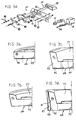
- FIGs 6 and 6A illustrate a physical construction of a mower (40) including aspects of the present invention.
- the mower itself comprises a mower deck (41) supported on wheels (42) with a suitable height adjustment mechanism (not shown).
- a catcher assembly (43) is provided adapted to receive cut grass from the mower deck (41).
- the mower deck and catcher are conveniently moulded from suitable plastics material to achieve a desired light weight and strength although other materials might also be usable.
- the cutter blade assembly (44) is relatively conventional and is not shown in Figures 7, 7A but can be seen in Figures 8A to 8D.
- the assembly comprises a disc (45) with two or more blades (46) pivotally mounted thereto. Other known forms of cutter assemblies could also be employed.
- the disc (45) is driven by an electric motor (10) which is electrically connected to the battery (11). Electrical connecting leads (46) to (51) are shown in Figures 1 and 6.
- the leads (47), (48) are interconnected by a safety switch (20) which comprises a pair of plate contacts (62) which are permitted to have limited pivotal movement about pivot points (53) by providing slightly oversized holes (54) through which fasteners (68) pass.
- An actuating key (52) is provided having a flat electrically conductive blade (71) and an electrically insulating handle (72). By insertion of the blade (71) through the receiving slot in the insulating housing (66), the blade (71) is then forced between the two contact plates (62) to establish an electrical path there between.
- the pivot arrangement of the contact plates (62) enables full edge contact between these plates and the blade (71) rather than a point contact that might result in the case of minor misalignment of the parts during assembly, thereby improving the electrical connection between leads (47) and (48).
- the safety switch (20) is provided to ensure that the battery is totally disabled or isolated when the mower is not in use.
- the key (52) has to be first inserted to make the primary connection between the leads (47), (48).
- the socket (55) for receiving the charging contact (56) of the transferer (18) is also provided adjacent to the safety switch (20).
- the hand (72) of the key (52) is advantageously enlarged so that when it is operationally inserted, it covers the charging socket (55) so that the socket is protected against ingress of dust, dirt or the like during use and also prevents the socket (55) from being inadvertently connected to an external power source while the mower is actually in a use mode.
- the motor (10) and the battery (11) are generally mounted within the upper cavity (57) in the deck (41). These are covered by cover members (58), (59) and a handle (60) is provided to which switch (12) is mounted.
- the deck (41) is constructed with an internal cavity design based on principles disclosed in Australian Patent No. 610546, that is, it is desirable that as the blades (45) approach the outlet chute into the catcher (43), there should be increasingly upward and outward space into which the cut grass can be thrown.
- This is generally illustrated in Figures 7A to 7C. This not only improves mowing efficiency but assists in depositing the cut grass in the rear of the catcher (43), rather than causing an obstruction in the front of the catcher.
- This arrangement has been found to work well but to produce a one piece moulded or formed deck with this negative outer skirt angle, over a sufficient circumferential length, has proved to be very difficult without the use of very expensive forming machinery.
- This difficulty has been solved by one aspect of the present invention wherein a separate false wall forming member (80) is provided adjacent the outlet chute to the catcher (43).
- This member (80) may conveniently be formed from metal sheet material and includes an inclined wall part (81) which is adapted to maintain the inclination of the outer skirt wall (for example as shown at (85) in Figure 7C) of the moulded deck cavity (86).
- the member (80) may also include a lower vertical section (82) and floor section (83) adapted to engage against the bottom edge zone of the deck skirt (87).
- the member (80) may also include a bridging transverse floor part (84) to overlie the connection between the catcher (43) and the deck (41).
Landscapes
- Life Sciences & Earth Sciences (AREA)
- Environmental Sciences (AREA)
- Engineering & Computer Science (AREA)
- Power Engineering (AREA)
- Harvester Elements (AREA)
Abstract
There is disclosed a lawn or grass mower having a
cutting mechanism (14) driven by an electric motor (10), the
electric motor (10) being powered by a rechargeable lead
acid batter (11), the battery (11) being protected against
damage caused as a result of over rapid discharge by control
means (13). The control means (13) is able to sequentially
sample battery voltage discharge levels and to determine
when the sampled battery voltage discharge level drops
rapidly at a rate higher than normal operational voltage
level drop. A disabling means (14) is arranged to disable
said battery means (11) from said mower (40) if the voltage
discharge level of said battery means (11) does not return
to a voltage level greater than a control level being a
preset differential (ΔV) below said reference voltage level
(V ref) within a predetermined period of time (ΔT).
Description
The present invention relates to improvements in
battery operated electric machines and in particular to
battery operated mowers.
It has been found that sealed lead acid batteries may
be used as a suitable power source for lawn mowers or the
like. Such batteries have the required performance
characteristics to operate satisfactorily as a power source
for an electric motor driving cutting blades of lawn or
grass cutting machine and they are capable of repeatedly
being recharged. They do, however, have the disadvantage
that if they are used in conditions in which their discharge
voltage drops too rapidly then the normal life expectancy of
the battery is drastically reduced.
When the term "battery" or "battery means" is used
hereinafter, it is intended to identify a battery or group
of batteries that have this characteristic.
It is therefore an object of the present invention to
provide control apparatus in the power supply system for
battery powered machines, particularly lawn or grass mowers,
which will prevent the battery from being rapidly discharged
to the extent that the discharge capacity or life of the
battery is substantially minimised (or ended).
Under certain possible adverse (to the battery)
conditions, it is desirable to be able automatically to
prevent use of the machine and thereby further discharge of
the battery voltage levels. Typically, such situations
arise where the work implement (cutting blades in the case
of a mower) are obstructed for some reason. In the case of a
mower this can occur as a result of the blades engaging an
immovable object such as a rock or by excessively heavy
grass conditions. In such circumstances, because of high
current loading, the discharge voltage level drops rapidly
but is also quickly recovered (if the obstruction exists
only momentarily) to a level below but close to the level
prior to the obstruction occurring. A similar
characteristic occurs at start up under normal conditions.
However, if the obstruction is more than transient, then the
voltage recovery is very slow to recover if at all to levels
well below the voltage level prior to the obstruction
occurring. The present invention therefore aims to provide
a means for disabling the machine to prevent battery damage
upon an obstruction to the work implement being recognised
without affecting the operation of the machine under normal
start up conditions.
Accordingly, the present invention provides control
apparatus for a rechargeable battery means of a battery
powered lawn or grass mower, said control apparatus
including monitoring means to monitor during use of the lawn
or grass mower voltage discharge levels of the battery means
and disabling means to disable said battery means from said
mower, characterised in that the control apparatus includes
means for establishing a predetermined reference voltage
level and for recognising a rapid drop in discharge voltage
level of the battery means at a rate higher than normal
operational voltage level drop, said disabling means being
arranged to disable said battery means from said mower if
the voltage discharge level of said battery means as
monitored by said monitoring means does not return to a
voltage level greater than a control level being a
preset differential below said reference voltage level
within a predetermined period of time.
Conveniently the aforesaid predetermined period of time
is determined from commencement of said rapid drop in
voltage level.
In a preferred embodiment, the predetermined reference
voltage level may be the voltage level sensed prior to said
rapid drop in voltage level.
In an alternative preferred embodiment, the reference
voltage level may be the voltage level sensed at each point
in time that operation of the machine commences. For
example, with a lawn mower, the first reference voltage
level would be the battery voltage level first sensed when
the handle operating switch is first moved to an operational
position. Thereafter, if the mower is stopped, for example
to empty the grass catcher, then the reference voltage is
the voltage level sensed when the handle operating switch is
reactivated to restart the mower.
The control apparatus is preferably also arranged to
disable said battery from the machine upon the monitored
discharge voltage of the battery dropping below a preset
minimum regardless of the circumstances.
Battery means also have the disadvantage that if they
are used to a stage where their discharge voltage drops
below a certain limit then they cannot be recharged or the
normal life expectancy of the battery is drastically
reduced. The point at which this occurs does, however,
depend to some extent on the rate of discharge of the
battery which also depends on the conditions of use. In a
lawn mower situation, it is conceivable that a user of the
mower might wish to over extend the battery simply to finish
a particular area prior to being forced to wait for a
reasonably extended period necessary for recharging the
battery. However, if this is done, the battery life will
either be substantially shortened or immediately ended
requiring the acquisition of a new battery for future
operation of the mower. Clearly this is an undesirable
circumstance which should be avoided if at all possible. In
known prior art arrangements, over current sensing control
devices have been used to disable the battery when current
is drawn from the battery above a certain rate; however,
these arrangements do not protect against battery failure
(or life reduction) as a result of voltage discharge below
the predetermined limits imposed by the battery
manufacturer.
Therefore, preferably the disabling means is arranged
to disable the battery means from said mower upon said
voltage discharge level dropping below a predetermined
minimum level for the battery means, said disabling means
preventing reuse of the machine until the battery means has
been recharged, preferably through a complete recharging
regime.
Conveniently, the battery powered machine includes a
motor adapted to drive a work implement such as cutting
blades in the case of a mower.
Preferably, the monitoring means includes a
microprocessor controller adapted
repeatedly to sample the voltage discharge level of the
battery during functional use of the battery powered machine
with said disabling means being activated immediately the
voltage level drops below said predetermined minimum level.
In accordance with a further aspect of the present
invention, a safety mechanism for an electrically powered
mower adapted to prevent inadvertent operation of the motor
of the mower is provided. In European Patent Application
No.466,306, there is disclosed a similar safety system
incorporating a key member adapted to be inserted to actuate
a switch mechanism from a normal circuit open position,
preventing mower operation, to a circuit closed position
when inserted allowing mower operation. One disadvantage of
this arrangement is that the key member is in fact only an
external actuator requiring a switch mechanism within the
mower housing which adds certain costs to the overall
assembly. Furthermore, only partial removal of the key
member could result in the switch mechanism being opened
allowing the key member to remain in position for possible
inadvertent reactivation in undesirable circumstances.
It is a further object of the present invention to
provide a disabling system of the aforementioned kind which
will avoid the costs of this separate switch mechanism and
which will also prevent inadvertent reactivation in
undesirable circumstances.
The present invention also provides a control means for
a mower comprising an electric motor adapted to drive a
cutter mechanism and electrical connection means between a
power source and said motor, said control means including
switch means being opened upon removing a switch operating
member from said mower and being closed by operationally
inserting said switch operating member into said mower, said
control means being characterised by said switch operating
member forming a part of the electrical connection means
when operationally inserted to close said switch means.
Conveniently, said operating member comprises an
electrically conductive blade element adapted to be inserted
between a pair of plate contact members whereby when the
switch means is closed, electrical contact is established
between the two plate contact members via said blade
element. Thus, the operating member needs to be removed
completely to open the switch means. Each of the plate
contact members may be mounted for at least limited movement
relative to said blade element to increase the degree of
electrical contact between each contact member and the blade
element.
Where the source of power comprises a
rechargeable battery, it is desirable to provide a
recharging connection means adjacent the aforesaid switch
means whereby in the closed position, an enlarged head
portion of the operating member may cover both the switch
means and the recharging connection means thereby protecting
same and preventing inadvertent connection of the recharging
means to an external source of power when the switch
operating member is inserted.
In accordance with a still further aspect of the
present invention there is provided a lawn or grass mower
including an electric motor driving a cutting means and a
rechargeable battery means for powering said electric motor,
said mower further including recharging means adapted for
connection to an external power source and when so
connected, said recharging means is adapted to pass said
battery through a defined recharging regime prior to
allowing reuse of said mower. The defined recharging regime
preferably comprises a first trickle charging stage from a
nominally flat condition of said battery means until the
battery means achieves a first predetermined voltage level,
a second charging stage where the battery means is charged
at close to or at a maximum charge rate possible for said
battery means until a second predetermined over charge
voltage level for the battery means is achieved, thereafter
maintaining charging of said battery means for a
predetermined period of time while ensuring battery voltage
does not exceed an upper limit for said battery means
greater than said second predetermined over charge voltage
level.
The control systems, described above have been
developed primarily for use in an electrically powered
mower. In relation to this mower development, it has been
proposed to use principles disclosed in Australian Patent
No. 610546 in the construction of the mower deck. In this
prior art specification it is proposed generally to provide
an increasing cavity volume adjacent the mower blades that
increases both in height and radially outwardly as the
blades approach the outlet chute to the mower catcher. Such
arrangements provide an outwardly and upwardly inclined
skirt over a significant proportion of the circumference of
the deck which has been found to be operationally valuable
but very difficult to make commercially with a one piece
moulded or otherwise formed deck without the use of very
expensive forming machinery. Thus, in accordance with a
further aspect of the present invention, a mower deck is
proposed comprising a one piece moulded or otherwise formed
deck housing member having a mowing cavity with an inner
facing wall extending upwardly and outwardly from a lower
zone of the deck around at least a part of the periphery of
the mowing cavity, and a false wall forming member adapted
to be mounted in said cavity to extend the peripheral length
of said part of the deck having said upwardly and outwardly
inclined inner facing wall. Conveniently, the separate
false wall forming member is located adjacent to an outlet
opening from said deck adapted in use to lead to a mower
catcher.
Preferred embodiments of the present invention are
hereinafter described with reference to the accompanying
drawings, in which:-
Referring to Figures 1 and 2 of the drawing, a
preferred embodiment of the present invention is depicted
comprising a motor (10) adapted to operate mower cutting
blades of any configuration (not illustrated). The motor
(10) is powered by a rechargeable battery (11) such as a
sealed lead acid battery nominally of 12 volts. A slider
switch (12) is provided on the mower handle which must be
activated by the mower user for power to be supplied from
the battery (11) to the motor (10). If the operator removes
his closing grip on the handle bar switch (12), then the
switch automatically moves to an open condition preventing
the battery (11) from supplying power to the motor (10).
The circuit arrangement further includes a controller (13)
in the form of a printed circuit board (PCB) and a motor
disabling relay (14) controlled by the controller (13). The
controller (13) senses loaded and unloaded battery terminal
voltage and the status of the handle switch (12). The
controller (13) further calculates rate of battery discharge
during a discharge regime, i.e. during normal mower
operation, and acts to operate the motor disabling relay
(14) should the battery terminal voltage drop below a preset
minimum voltage or should the control recognise a rapid drop
in voltage (at a rate far greater than a normal use
discharge rate) which is not recovered to a level greater
than a preset differential ΔV (typically 1.6 volt
differential) below a predetermined reference voltage within
a predetermined time period Δt. This reference voltage may
be the voltage level sensed at the time of operating the
handle bar switch (12), or immediately prior to the abnormal
rapid drop. Figure 3A illustrates normal and abnormal
voltage discharge situations during use of a mower wherein
the reference voltage level set is the voltage level sensed
immediately before the abnormal rapid voltage drop. For
example, the voltage level at start up with a fully charged
battery may be nominally at 12 volts. At start up under
normal circumstances there would be rapid drop in sensed
voltage level (full line 21) followed by a rapid recovery
(full line 22) to a level approximating the start up voltage
level. If, however, something might be obstructing the
mower blades, (for example a rock or long grass) then the
voltage recovery curve might follow the broken line (23) and
(24), i.e. after the expiry of the interval Δt; the battery
would be immediately disabled, that is electrically
disconnected from its load, the motor (10). If we assume,
however, that no such problem arises during start up, then
the battery would be discharged in normal use following a
curve such as indicated by full line (25). Again, if the
mower blades strike an obstruction during use then there
will again be a rapid drop, for example from (26) following
line (27) which could be recovered following line (28) if
temporary or following broken line (29) if it is more than a
mere transitory obstruction. Thus, during use, in such
circumstances, if the voltage level is recovered to a
voltage level greater than ΔV below the voltage level at the
commencement of the rapid drop at (26) within a time period
Δt, then normal use is continued. However, if the Δt time
period expires before this voltage level is recovered (e.g.
broken line 29), then the battery is electrically
disconnected from the motor at the expiry of the Δt period
(point 30). As is also shown in Figure 3A, if the battery
discharge voltage drops below a predetermined minimum V L
(nominally 6 volts in this illustration), either due to an
abnormal voltage drop (line 31) or simply as a result of
normal battery discharge (line 32), then the battery is
immediately disabled, i.e. electrically disconnected from
the motor, for example at point 33 or 34. This electrical
disconnection is in each case performed by the relay 14.
The controller 13 is then arranged such that the relay 14
cannot be reactivated until after a defined battery
recharging regime has been completed.
Figure 3B illustrates a possible alternative to that of
Figure 3A. In this case the predetermined reference voltage
is the voltage level sensed at each point the mower is
restarted. For example, if the mower has been used for a
period of time and then stopped (for any reason), the
battery level will have dropped through this use to point A.
If the mower is reactivated, the sensed voltage level at
this point of activation becomes the reference voltage Vref
until such time as the mower is stopped and again
reactivated. If there is a sudden drop in voltage (as
discussed above with reference to Figure 3A) then so long as
the voltage level is recovered to a level greater than ΔV
below Vref, then normal operation continues. If this
recovery does not occur within the period Δt then the
battery is disabled immediately. Thus, the difference
between Figures 3A and 3B is that in Figure 3A, the
reference voltage is always the sensed voltage level
immediately before any abnormal voltage drop whereas in
Figure 3B, the reference voltage is the sensed voltage level
at start up of the machine immediately before the rapid
voltage drop.
The control system conveniently includes two visual
displays comprising a power on LED (15) and charge required
LED (16). The power on LED (15) illuminated when the
charger (17) is connected to a power source (commonly a
conventional 240V alternating supply) via a suitable
transformer (18) and plug (19). The charge required
LED (16) commences to flash and a warning buzzer or beeper
sounds when the relay (14) has been activated indicating
recharging of the battery is required. When the power on
LED (15) is activated indicating the battery has been
connected to a power source via the charger (17), the charge
required LED (16) remains continuously illuminated until the
charging regime is completed. Should the battery not be
connected to a power source as aforesaid when recharging is
required, the aforesaid warning sound and light is continued
for a predetermined period of time and is thereafter
continued with a longer period between each illumination of
the LED (16) and sounding of the warning buzzer, beeper or
the like until the battery terminal voltage drops to a
second preset level V X below V L where the battery charge is
protected by discontinuing the warning light and sounds.
Typically V X might be set at nominally one volt below V L .
Figure 4 of the accompanying drawings illustrates a
typical preferred charge, charge regime for the control
apparatus of the present invention. If the battery is in a
nominally flat condition, it cannot accept a high charge
rate. Therefore it is a trickle charged until voltage V T is
reached. The circuit then switches to a bulk charge regime
where the battery can be charged at close to or at the
maximum charge rate possible. As the battery voltage builds
up to V 23 , the circuit changes to stage 3, the "overcharge"
stage (point C on the charge voltage curve). When the
battery reaches point D on the voltage curve, the charging
current begins to taper off (charge current curve). Upon
reaching point E, the battery voltage is equal to V oc
(overcharge voltage) and the circuit switches abruptly to
stage 4. At this point a timer (say 3 hours) is started and
the current is modulated to ensure that the battery voltage
does not exceed say 15.2 volts. This ensures that the
battery receives sufficient overcharge to ensure 100%
discharge capacity. At the end of the predetermined time,
all current is stopped. The battery terminal voltage will
drop quickly to say 13.2 volts, the "natural" voltage of the
cell stack. Prom this point, the battery will
'self-discharge' at a very low rate until a predetermined
voltage of say 12 volts. At this point the charger will
reinitiate the charge regime. Of course, because the
battery is only slightly discharged, the charger will cycle
through the first stages quite quickly until the timer is
again initiated. A full predetermined (say three hours)
time will be imposed again. At stage 5, the charge required
LED (16) is deactivated with the power LED (15) still
activated and the relay (14) is enabled to allow the motor
to be reconnected to the battery for further use as may be
required. A second option would be to charge until point E
on the voltage curve and then leave the charger on at say
13.8 volts for continuous 'float' charging. In this mode,
after a predetermined time in 'float', the "charge-required"
LED (16) would be deactivated to signal that the unit is
ready for use, and the relay (14) would be enabled to allow
further use.
Figure 5 illustrates in block diagram form the control
functions of the controller 13 during differing modes and
conditions sensed by the control system. The functions are
further indicated by the following table:


Figures 6 and 6A illustrate a physical construction of
a mower (40) including aspects of the present invention.
The mower itself comprises a mower deck (41) supported on
wheels (42) with a suitable height adjustment mechanism (not
shown). A catcher assembly (43) is provided adapted to
receive cut grass from the mower deck (41). The mower deck
and catcher are conveniently moulded from suitable plastics
material to achieve a desired light weight and strength
although other materials might also be usable. The cutter
blade assembly (44) is relatively conventional and is not
shown in Figures 7, 7A but can be seen in Figures 8A to 8D.
The assembly comprises a disc (45) with two or more blades
(46) pivotally mounted thereto. Other known forms of cutter
assemblies could also be employed. The disc (45) is driven
by an electric motor (10) which is electrically connected to
the battery (11). Electrical connecting leads (46) to (51)
are shown in Figures 1 and 6.
As can be seen in Figures 6 and 6A, the leads (47),
(48) are interconnected by a safety switch (20) which
comprises a pair of plate contacts (62) which are permitted
to have limited pivotal movement about pivot points (53) by
providing slightly oversized holes (54) through which
fasteners (68) pass. An actuating key (52) is provided
having a flat electrically conductive blade (71) and an
electrically insulating handle (72). By insertion of the
blade (71) through the receiving slot in the insulating
housing (66), the blade (71) is then forced between the two
contact plates (62) to establish an electrical path there
between. The pivot arrangement of the contact plates (62)
enables full edge contact between these plates and the blade
(71) rather than a point contact that might result in the
case of minor misalignment of the parts during assembly,
thereby improving the electrical connection between leads
(47) and (48). The safety switch (20) is provided to ensure
that the battery is totally disabled or isolated when the
mower is not in use. For the mower to be used, the key (52)
has to be first inserted to make the primary connection
between the leads (47), (48).
The socket (55) for receiving the charging contact (56)
of the transferer (18) is also provided adjacent to the
safety switch (20). The hand (72) of the key (52) is
advantageously enlarged so that when it is operationally
inserted, it covers the charging socket (55) so that the
socket is protected against ingress of dust, dirt or the
like during use and also prevents the socket (55) from being
inadvertently connected to an external power source while
the mower is actually in a use mode.
As is shown in Figure 6, the motor (10) and the battery
(11) are generally mounted within the upper cavity (57) in
the deck (41). These are covered by cover members (58), (59)
and a handle (60) is provided to which switch (12) is
mounted.
The deck (41) is constructed with an internal cavity
design based on principles disclosed in Australian Patent
No. 610546, that is, it is desirable that as the blades (45)
approach the outlet chute into the catcher (43), there
should be increasingly upward and outward space into which
the cut grass can be thrown. This is generally illustrated
in Figures 7A to 7C. This not only improves mowing
efficiency but assists in depositing the cut grass in the
rear of the catcher (43), rather than causing an obstruction
in the front of the catcher. This arrangement has been
found to work well but to produce a one piece moulded or
formed deck with this negative outer skirt angle, over a
sufficient circumferential length, has proved to be very
difficult without the use of very expensive forming
machinery. This difficulty has been solved by one aspect of
the present invention wherein a separate false wall forming
member (80) is provided adjacent the outlet chute to the
catcher (43).
This member (80) may conveniently be formed from metal
sheet material and includes an inclined wall part (81) which
is adapted to maintain the inclination of the outer skirt
wall (for example as shown at (85) in Figure 7C) of the
moulded deck cavity (86). The member (80) may also include
a lower vertical section (82) and floor section (83) adapted
to engage against the bottom edge zone of the deck skirt
(87). As will be seen, in the cavity of the member (80),
there is either no outward inclination of the skirt (87) or
the angle might be slightly in the reverse direction to
facilitate formation of the deck. The member (80) may also
include a bridging transverse floor part (84) to overlie the
connection between the catcher (43) and the deck (41).
Claims (18)
- A control apparatus for a rechargeable battery means (11) of a battery powered lawn or grass mower (40) said control apparatus including monitoring means (13) to monitor during use of the lawn or grass mower voltage discharge levels of the battery means (11) and disabling means (14) to disable said battery means (11) from said mower (40), characterised in that the control apparatus includes means for establishing a predetermined reference voltage level (V ref) and for recognising a rapid drop in discharge voltage level of the battery means (11) at a rate higher than normal operational voltage level drop, said disabling means (14) being arranged to disable said battery means (11) from said mower (40) if the voltage discharge level of said battery means (11) as monitored by said monitoring means (13) does not return to a voltage level greater than a control level, said control level being a preset differential (ΔV) below said reference voltage level (V ref), within a predetermined period of time (ΔT).
- A control apparatus according to claim 1 characterised in that the disabling means (14) is arranged to disable said battery means (11) from said mower (40) upon said voltage discharge level dropping below a predetermined minimum level for the battery means (11) said disabling means (14) preventing reuse of the mower (40) until the battery means (11) has been recharged.
- A control apparatus according to claim 2 characterised in that the said disabling means prevents reuse of the mower (40) until the battery means (11) has been recharged through a complete recharging regime.
- A control apparatus according to any one of claims 1 to 3 characterised in that the said battery means (11) comprises a single sealed lead acid battery.
- A control apparatus according to any one of claims 1 to 4 characterised in that the monitoring means (13) includes a micro processor controller arranged repeatedly to sample voltage discharge levels of the battery means (11) during functional use of the mower (40).
- A control apparatus according to any one of claims 1 to 5, characterised in that the predetermined period of time (ΔT) commences at the time of said rapid drop in voltage level.
- A control apparatus according to any one of claims 1 to 6, characterised in that the predetermined reference voltage (V ref) is the voltage level sampled immediately prior to said rapid drop in voltage level.
- A control apparatus according to any one of claims 1 to 6, characterised in that the predetermined reference voltage (V ref) is the voltage level sampled at each point in time that operation of the mower (40) is commenced.
- A control apparatus according to any one of claims 1 to 8, characterised in that it further includes switch means (20) adapted to be opened to prevent operation of the mower (40) and to be closed to permit operation of the mower (40), said switch means (20) including an independent switch operating member (52) capable of being removed from said switch means (20) to enable opening of said switch means (20).
- A control apparatus according to claim 9 wherein when said switch operating member (52) is inserted into said switch means (20) said switch operating member (52) forms part of electrical connection means (46), (47), (48) from the battery means (11) to a motor (10) of said mower (40) to close said switch means (20).
- A control apparatus according to claim 1 for a mower comprising an electric motor (10) adapted to drive a cutter mechanism (44) and electrical connection means (46), (47), (48) between a power source (11) and said motor (10) said control apparatus including switch means (20) being opened upon removing a switch operating member (52) from said switch means (20) and being closed by operationally inserting said switch operating member (52) into said switch means (20), said control apparatus being characterised by said switch operating member (52) forming a part of the electrical connection means (46), (47), (48) when operationally inserted to close said switch means (20).
- A lawn or grass mower including control apparatus according to any one of claims 1 to 11.
- A lawn or grass mower (40) including an electric motor (10) driving a cutting means (44) and a rechargeable battery means (11) for powering said electric motor (10), said mower (40) further including control means for controlling operation of said motor (10) by said battery means (11), said control means including monitoring means (13) to monitor, during use of the mower (40), voltage discharge levels of the battery means (11), and disabling means (14) to disable said battery means (11) from said mower (40), characterised in that the control apparatus includes means for establishing a predetermined reference voltage level (V ref) and for recognising a rapid drop in discharge voltage level of the battery means (11) at a rate higher than normal operational voltage level drop, said disabling means (14) being arranged to disable said battery means (11) from said mower (40) if the voltage discharge level of said battery means (11) as monitored by said monitoring means (13) does not return to a voltage level greater than a control level, said control level being a preset differential (ΔV) below said reference voltage (Vref), within a predetermined period of time (ΔT).
- A mower according to claim 13 characterised in that the disabling means (14) is arranged to disable said battery means (11) from said mower (40) upon said voltage discharge level dropping below a predetermined minimum level for the battery means (11) said disabling means (14) preventing reuse of the mower (40) until the battery means (11) has been recharged to a predetermined level by completing a defined recharging regime.
- A mower according to any one of claims 13 or 14 characterised in that said control means further includes recharging means (55,13) adapted for connection to an external power source and when so connected, said recharging means (55,13) being adapted to pass said battery means through a defined recharging regime.
- A lawn or grass mower according to claim 15 wherein said recharging means is carried by said mower (40).
- A lawn or grass mower (40) according to claim 15 or claim 16 wherein said defined recharging regime comprises a first trickle charging stage from a nominally flat condition of said battery means (11) until the battery means (11) achieves a first predetermined voltage level (VT), a second charging stage where the battery means (11) is charged at close to or at a maximum charge rate possible for said battery means (11) until a second predetermined over charge voltage level (Voc) for the battery means (11) is achieved, thereafter maintaining charging of said battery means (11) for a predetermined period of time while ensuring battery voltage does not exceed an upper limit for said battery means (11) greater than said second predetermined over charge voltage level (Voc).
- A lawn or grass mower (40) according to claim 17 wherein said defined charging regime is terminated upon completion of said predetermined period of time and is automatically recommenced while the charging means (55, 13) remains connected to the source of electric power upon voltage levels dropping to a predetermined differential level below said second predetermined over charge voltage level (Voc).
Applications Claiming Priority (3)
| Application Number | Priority Date | Filing Date | Title |
|---|---|---|---|
| AUPL417992 | 1992-08-18 | ||
| AUPL4179/92 | 1992-08-18 | ||
| EP19930306429 EP0585021A3 (en) | 1992-08-18 | 1993-08-16 | Improvements in battery operated electric machines |
Related Parent Applications (1)
| Application Number | Title | Priority Date | Filing Date |
|---|---|---|---|
| EP19930306429 Division EP0585021A3 (en) | 1992-08-18 | 1993-08-16 | Improvements in battery operated electric machines |
Publications (1)
| Publication Number | Publication Date |
|---|---|
| EP0817352A2 true EP0817352A2 (en) | 1998-01-07 |
Family
ID=3776363
Family Applications (2)
| Application Number | Title | Priority Date | Filing Date |
|---|---|---|---|
| EP97111886A Pending EP0817352A2 (en) | 1992-08-18 | 1993-08-16 | Improvements in battery operated electric machines |
| EP19930306429 Withdrawn EP0585021A3 (en) | 1992-08-18 | 1993-08-16 | Improvements in battery operated electric machines |
Family Applications After (1)
| Application Number | Title | Priority Date | Filing Date |
|---|---|---|---|
| EP19930306429 Withdrawn EP0585021A3 (en) | 1992-08-18 | 1993-08-16 | Improvements in battery operated electric machines |
Country Status (2)
| Country | Link |
|---|---|
| US (1) | US5490370A (en) |
| EP (2) | EP0817352A2 (en) |
Cited By (4)
| Publication number | Priority date | Publication date | Assignee | Title |
|---|---|---|---|---|
| FR2900285A1 (en) * | 2006-04-20 | 2007-10-26 | Pubert Henri Sas Soc Par Actio | MOTOCULTURE ELECTRICAL EQUIPMENT |
| EP1407641A4 (en) * | 2001-06-28 | 2010-05-12 | Skyworks Solutions Inc | STRUCTURE AND METHOD FOR MANUFACTURING A DRIVER'S HOLDER WITHOUT DRIVER |
| CN102422750A (en) * | 2011-08-23 | 2012-04-25 | 宁波大叶园林设备有限公司 | Riding mower with safety circuit protection measures |
| EP4464145A1 (en) * | 2023-05-19 | 2024-11-20 | Iseki & Co., Ltd. | Grass cutter |
Families Citing this family (47)
| Publication number | Priority date | Publication date | Assignee | Title |
|---|---|---|---|---|
| US5606851A (en) * | 1993-09-22 | 1997-03-04 | Briggs & Stratton Corporation | Battery-powered lawn cutting system |
| FR2720561B1 (en) * | 1994-05-24 | 1996-08-23 | Electromobiles Rochelaises Ste | Device for limiting the discharge of electric storage batteries, in particular electric vehicle traction. |
| CA2150663A1 (en) * | 1994-07-22 | 1996-01-23 | William Ishmael | Control system |
| JP2837960B2 (en) * | 1994-08-22 | 1998-12-16 | ブリッグス・アンド・ストラットン・コーポレイション | Improved battery powered mower |
| JP3712754B2 (en) * | 1994-12-27 | 2005-11-02 | ヤマハ発動機株式会社 | Secondary battery deep discharge prevention device |
| GB2336955B (en) * | 1995-05-30 | 1999-12-15 | Motorola Inc | Power control method and apparatus suitable for use in a radio communication device |
| US6571091B1 (en) | 1995-05-30 | 2003-05-27 | Motorola, Inc. | Power control method and apparatus suitable for use in a radio communication device |
| GB2303719B (en) * | 1995-07-26 | 2000-01-26 | Black & Decker Inc | An energy management system for a cordless vegetation cutter |
| US6170241B1 (en) | 1996-04-26 | 2001-01-09 | Tecumseh Products Company | Microprocessor controlled motor controller with current limiting protection |
| US5727372A (en) * | 1996-05-30 | 1998-03-17 | The Toro Company | On-board charging system for electric lawn mower |
| US5934051A (en) * | 1997-02-06 | 1999-08-10 | Textron, Inc. | Solid state mow system for electrically powered mower |
| US6242891B1 (en) * | 1997-09-01 | 2001-06-05 | Batteryguard Limited | Battery charge indicator |
| GB2331908A (en) * | 1997-12-03 | 1999-06-09 | Joseph Charteris | Cordless electric grass lawn mower |
| GB2338392A (en) * | 1998-06-16 | 1999-12-22 | Black & Decker Inc | Switch for battery powered lawn mower. |
| US6523334B1 (en) * | 2000-10-26 | 2003-02-25 | Textron Inc. | Battery-powered walk-behind greensmower |
| US7007446B2 (en) * | 2000-10-26 | 2006-03-07 | Textron Inc. | Battery-powered walk-behind greensmower |
| JP2003061438A (en) * | 2001-08-22 | 2003-03-04 | Honda Motor Co Ltd | Electric lawn mower |
| JP3776773B2 (en) * | 2001-08-22 | 2006-05-17 | 本田技研工業株式会社 | Electric lawn mower |
| TWI248783B (en) * | 2001-08-22 | 2006-02-11 | Honda Motor Co Ltd | Electric lawn mower |
| US6904740B2 (en) * | 2003-02-11 | 2005-06-14 | Textron Inc. | Articulating handle for a walk-behind mower |
| US7240756B2 (en) * | 2004-05-21 | 2007-07-10 | Textron Inc. | Method of operator presence control on walk behind powered equipment |
| US7367173B2 (en) * | 2005-03-02 | 2008-05-06 | Textron Inc. | Greens mower data display and controller |
| US7677017B2 (en) * | 2005-06-28 | 2010-03-16 | Textron Innovations Inc. | Modular power source for walk-behind mower |
| US8732896B2 (en) | 2006-10-17 | 2014-05-27 | Mtd Products Inc | Hybrid electric cleaning device |
| WO2008048615A2 (en) | 2006-10-17 | 2008-04-24 | Desa Ip, Llc | Hybrid electric device |
| US20080120955A1 (en) * | 2006-10-17 | 2008-05-29 | Lucas Delbert R | Hybrid electric lawnmower |
| US7728534B2 (en) * | 2006-10-17 | 2010-06-01 | Mtd Products Inc | Hybrid electric lawnmower |
| US7479754B2 (en) | 2006-10-17 | 2009-01-20 | Desa Ip Llc | Hybrid electric lawnmower |
| US8076873B1 (en) | 2007-06-01 | 2011-12-13 | Mtd Products Inc | Hybrid outdoor power equipment |
| US8653786B2 (en) * | 2008-04-25 | 2014-02-18 | Black & Decker Inc. | Cordless mower including battery with two charging connectors |
| US8429885B2 (en) * | 2008-04-25 | 2013-04-30 | Black & Decker Inc. | Cordless mower including cooling air flow arrangement |
| US20090266042A1 (en) * | 2008-04-25 | 2009-10-29 | Mooney P Wade | Mower |
| US8627897B2 (en) | 2008-09-03 | 2014-01-14 | Black & Decker Inc. | Tiller housing |
| US7963344B2 (en) * | 2008-09-03 | 2011-06-21 | Black & Decker Inc. | Tiller with removable battery |
| US7762049B2 (en) * | 2008-12-31 | 2010-07-27 | Black & Decker Inc. | Electric mower having two-motion activation system |
| USD620029S1 (en) | 2009-09-11 | 2010-07-20 | Black & Decker Inc. | Mower |
| USD620030S1 (en) | 2009-09-11 | 2010-07-20 | Black & Decker Inc. | Mower |
| JP5694065B2 (en) * | 2011-06-14 | 2015-04-01 | 株式会社マキタ | Electric lawn mower |
| DE102011106578A1 (en) * | 2011-06-16 | 2012-12-20 | Andreas Stihl Ag & Co. Kg | Battery-operated electric motor in a working device |
| US9199546B2 (en) * | 2011-12-31 | 2015-12-01 | Club Car, Llc | Audible confirmation of battery charging in electric vehicles |
| EP2821874B1 (en) | 2012-03-02 | 2017-08-02 | Positec Power Tools (Suzhou) Co., Ltd | Automatically travelling device and control method therefor |
| EP2641460B1 (en) * | 2012-03-19 | 2014-03-12 | Fabrizio Bernini | Apparatus for cutting grass |
| US8907596B2 (en) | 2012-05-01 | 2014-12-09 | Deere & Company | Method and system for controlling electric motors of a common assembly |
| US9167737B2 (en) | 2013-05-22 | 2015-10-27 | Carts & Tools Technology, Inc. | Garden implement |
| CN103299780A (en) * | 2013-06-26 | 2013-09-18 | 苏州金威特工具有限公司 | Electric mower with battery jar |
| AU2019445992B2 (en) * | 2019-05-10 | 2022-12-01 | Kaaz Corporation | Electric Work Machine with Cutting Blade |
| JP2023000199A (en) * | 2021-06-17 | 2023-01-04 | 株式会社デンソー | Actuator controller |
Family Cites Families (33)
| Publication number | Priority date | Publication date | Assignee | Title |
|---|---|---|---|---|
| DE221906C (en) * | 1909-01-21 | 1910-05-12 | Belt clamp | |
| US3581480A (en) * | 1969-09-30 | 1971-06-01 | Black & Decker Mfg Co | Multiple-function receptacle and interconnecting plugs therefor |
| DE2032695A1 (en) * | 1970-07-02 | 1972-01-05 | AS-Motor GmbH & Co. KG, 7163 Oberrot | Electric, in particular battery-operated lawn mowers |
| DE2217351A1 (en) * | 1972-04-11 | 1973-10-31 | Wolf Geraete Gmbh | ELECTRIC POWERED LAWN MOWER |
| US3821626A (en) * | 1973-06-18 | 1974-06-28 | United Aircraft Corp | Battery peaking unit for fuel cell power plants |
| US3823358A (en) * | 1973-06-18 | 1974-07-09 | United Aircraft Corp | Battery peaking unit for fuel cell power plants |
| GB1451129A (en) * | 1973-06-27 | 1976-09-29 | Gen Motors Corp | Milling cutters |
| US4201463A (en) * | 1977-05-17 | 1980-05-06 | Canon Kabushiki Kaisha | Photographic camera device |
| US4333302A (en) * | 1981-03-13 | 1982-06-08 | Ronald Thomas | Combined A.C./D.C. electric lawn mower |
| DE3218148C2 (en) * | 1982-05-14 | 1984-05-03 | Deta-Akkumulatorenwerk Gmbh, 3422 Bad Lauterberg | Method and device for displaying the discharge status and for controlling the charging of a drive accumulator |
| US4558281A (en) * | 1982-06-12 | 1985-12-10 | Lucas Industries | Battery state of charge evaluator |
| DE3304708C2 (en) * | 1983-02-11 | 1986-01-09 | Jungheinrich Unternehmensverwaltung Kg, 2000 Hamburg | Control arrangement for an electrically powered wheelchair |
| DE3334128A1 (en) * | 1983-09-17 | 1985-04-04 | Licentia Patent-Verwaltungs-Gmbh, 6000 Frankfurt | Method and circuit arrangement for determining the remaining distance which can be covered by a battery-driven electric vehicle |
| GB2192102A (en) * | 1986-06-27 | 1987-12-31 | Chinahong Industry Dev Limited | Battery protection and charging unit |
| US4849681A (en) * | 1987-07-07 | 1989-07-18 | U.S. Philips Corporation | Battery-powered device |
| US4835453A (en) * | 1987-07-07 | 1989-05-30 | U.S. Philips Corp. | Battery-powered device |
| US4882896A (en) * | 1988-04-11 | 1989-11-28 | Wilcox Roy E | Lawn mower |
| DE3815651A1 (en) * | 1988-05-07 | 1989-11-16 | Scintilla Ag | MOTORIZED GRASS SHEARS |
| KR910006494B1 (en) * | 1988-07-13 | 1991-08-27 | 삼성전자 주식회사 | Device exchanging battery in non-human carrier |
| US5159272A (en) * | 1988-07-27 | 1992-10-27 | Gnb Incorporated | Monitoring device for electric storage battery and configuration therefor |
| FR2636498A1 (en) * | 1988-09-20 | 1990-03-23 | Balva Claude | Lawnmower device powered by a battery |
| DE3844093A1 (en) * | 1988-12-28 | 1990-07-05 | Metabowerke Kg | ELECTRIC HAND TOOL WITH INDEPENDENT POWER SUPPLY |
| US5022587A (en) * | 1989-06-07 | 1991-06-11 | Hochstein Peter A | Battery powered nebulizer |
| US4942723A (en) * | 1989-09-21 | 1990-07-24 | Wassell Stephen R | Solar powered lawnmower |
| FR2652202B1 (en) * | 1989-09-21 | 1996-10-25 | Marjana Pretnar | METHOD FOR ANALYZING THE BATTERY CHARGE STATE. |
| US4995227A (en) * | 1989-10-25 | 1991-02-26 | Foster Harry C | Power assisted reel type lawn mower |
| EP0424577A1 (en) * | 1989-10-26 | 1991-05-02 | Maharishi Technology Corporation B.V. | Electric traction system |
| JP2893603B2 (en) * | 1989-11-22 | 1999-05-24 | 富士重工業株式会社 | Electric car |
| US4987729A (en) * | 1990-04-10 | 1991-01-29 | Paytas Anthony R | Solar powered mower |
| US5085043A (en) * | 1990-06-01 | 1992-02-04 | Black & Decker Inc. | Electro-mechanical interlock and module system for lawn mower or other electrical device |
| JPH04201752A (en) * | 1990-11-30 | 1992-07-22 | Kawasaki Heavy Ind Ltd | Method for preventing overdischarge of electric motor-driven work machine |
| FR2682330B1 (en) * | 1991-10-11 | 1994-09-16 | Peugeot Automobiles | SYSTEM FOR CONTROLLING THE ENERGY OF A BATTERY SUPPLYING AN ELECTRIC MOTOR OF DRIVE OF A VEHICLE. |
| US5301494A (en) * | 1992-07-24 | 1994-04-12 | Ryobi Motor Products Corp. | Recharging system for a battery operated tool having an on-board transformer |
-
1993
- 1993-08-16 EP EP97111886A patent/EP0817352A2/en active Pending
- 1993-08-16 EP EP19930306429 patent/EP0585021A3/en not_active Withdrawn
- 1993-08-18 US US08/108,470 patent/US5490370A/en not_active Expired - Lifetime
Cited By (8)
| Publication number | Priority date | Publication date | Assignee | Title |
|---|---|---|---|---|
| EP1407641A4 (en) * | 2001-06-28 | 2010-05-12 | Skyworks Solutions Inc | STRUCTURE AND METHOD FOR MANUFACTURING A DRIVER'S HOLDER WITHOUT DRIVER |
| FR2900285A1 (en) * | 2006-04-20 | 2007-10-26 | Pubert Henri Sas Soc Par Actio | MOTOCULTURE ELECTRICAL EQUIPMENT |
| WO2007122169A3 (en) * | 2006-04-20 | 2008-04-24 | Pubert Henri Sas | Electric power hoe |
| FR2947395A1 (en) * | 2006-04-20 | 2010-12-31 | Pubert Henri Sas | MOTOCULTURE ELECTRICAL EQUIPMENT |
| CN101460048B (en) * | 2006-04-20 | 2011-03-16 | 皮贝尔亨利股份有限公司 | electric tiller |
| US8286721B2 (en) | 2006-04-20 | 2012-10-16 | Pubert Henri Sas | Electric power hoe |
| CN102422750A (en) * | 2011-08-23 | 2012-04-25 | 宁波大叶园林设备有限公司 | Riding mower with safety circuit protection measures |
| EP4464145A1 (en) * | 2023-05-19 | 2024-11-20 | Iseki & Co., Ltd. | Grass cutter |
Also Published As
| Publication number | Publication date |
|---|---|
| EP0585021A3 (en) | 1994-05-18 |
| US5490370A (en) | 1996-02-13 |
| EP0585021A2 (en) | 1994-03-02 |
Similar Documents
| Publication | Publication Date | Title |
|---|---|---|
| US5490370A (en) | Battery operated electric machines | |
| US5619845A (en) | Battery-powered lawn cutting system | |
| US10593991B2 (en) | Method and system for battery protection | |
| AU684928B2 (en) | Improved battery-powered lawn cutting system | |
| US6320351B1 (en) | Intelligent switch for battery | |
| US7540132B2 (en) | Electric working machine | |
| US10431857B2 (en) | Lithium-based battery pack | |
| AU2007216856B2 (en) | Adaptor, assembly of battery pack and adaptor, and electric tool with the same | |
| US5894715A (en) | Mounting apparatus for connecting a power head to a device | |
| US6826895B2 (en) | Electric lawn mower | |
| GB2303530A (en) | Battery powered grass cutting device | |
| WO2001086735A2 (en) | Intelligent switch for battery | |
| CN107743674B (en) | self-propelled electronic equipment | |
| US20240380228A1 (en) | Interface Module for Operating an Electrical Consumer with at Least One Exchangeable Energy Storage Device and a Method for Controlling the Electrical Consumer by Means of the Interface Module | |
| KR100352330B1 (en) | Over charge/over discharge portection circuit for rechargerble battery of vaccum cleaner | |
| KR200171699Y1 (en) | Over charge/over discharge portection circuit for rechargerble battery of vaccum cleaner | |
| JP2012005287A (en) | Charger |
Legal Events
| Date | Code | Title | Description |
|---|---|---|---|
| PUAI | Public reference made under article 153(3) epc to a published international application that has entered the european phase |
Free format text: ORIGINAL CODE: 0009012 |
|
| STAA | Information on the status of an ep patent application or granted ep patent |
Free format text: STATUS: THE APPLICATION HAS BEEN PUBLISHED |
|
| AC | Divisional application: reference to earlier application |
Ref document number: 585021 Country of ref document: EP |
|
| AK | Designated contracting states |
Kind code of ref document: A2 Designated state(s): DE FR GB SE |