EP0816885A2 - Câble optique avec armatureet son utilisation - Google Patents
Câble optique avec armatureet son utilisation Download PDFInfo
- Publication number
- EP0816885A2 EP0816885A2 EP97109340A EP97109340A EP0816885A2 EP 0816885 A2 EP0816885 A2 EP 0816885A2 EP 97109340 A EP97109340 A EP 97109340A EP 97109340 A EP97109340 A EP 97109340A EP 0816885 A2 EP0816885 A2 EP 0816885A2
- Authority
- EP
- European Patent Office
- Prior art keywords
- wire
- layer
- cable
- optical cable
- wires
- Prior art date
- Legal status (The legal status is an assumption and is not a legal conclusion. Google has not performed a legal analysis and makes no representation as to the accuracy of the status listed.)
- Granted
Links
- 230000003287 optical effect Effects 0.000 title claims abstract description 71
- 238000005452 bending Methods 0.000 claims abstract description 47
- 239000013307 optical fiber Substances 0.000 claims abstract description 25
- 229910052751 metal Inorganic materials 0.000 claims abstract description 12
- 239000002184 metal Substances 0.000 claims abstract description 12
- 239000011343 solid material Substances 0.000 claims abstract description 3
- 239000012744 reinforcing agent Substances 0.000 claims description 17
- 239000000835 fiber Substances 0.000 claims description 16
- 239000010935 stainless steel Substances 0.000 claims description 16
- 229910001220 stainless steel Inorganic materials 0.000 claims description 16
- 230000002787 reinforcement Effects 0.000 claims description 10
- 239000004033 plastic Substances 0.000 claims description 8
- 229920003023 plastic Polymers 0.000 claims description 8
- 229910052782 aluminium Inorganic materials 0.000 claims description 7
- XAGFODPZIPBFFR-UHFFFAOYSA-N aluminium Chemical compound [Al] XAGFODPZIPBFFR-UHFFFAOYSA-N 0.000 claims description 7
- 229910000639 Spring steel Inorganic materials 0.000 claims description 5
- 229910000831 Steel Inorganic materials 0.000 claims description 5
- 239000010959 steel Substances 0.000 claims description 5
- 239000004952 Polyamide Substances 0.000 claims description 2
- 229920002647 polyamide Polymers 0.000 claims description 2
- 229920002635 polyurethane Polymers 0.000 claims description 2
- 239000004814 polyurethane Substances 0.000 claims description 2
- 230000003014 reinforcing effect Effects 0.000 claims 1
- 241001465754 Metazoa Species 0.000 description 4
- 230000007797 corrosion Effects 0.000 description 3
- 238000005260 corrosion Methods 0.000 description 3
- 229910000838 Al alloy Inorganic materials 0.000 description 2
- 230000005540 biological transmission Effects 0.000 description 2
- RNFJDJUURJAICM-UHFFFAOYSA-N 2,2,4,4,6,6-hexaphenoxy-1,3,5-triaza-2$l^{5},4$l^{5},6$l^{5}-triphosphacyclohexa-1,3,5-triene Chemical compound N=1P(OC=2C=CC=CC=2)(OC=2C=CC=CC=2)=NP(OC=2C=CC=CC=2)(OC=2C=CC=CC=2)=NP=1(OC=1C=CC=CC=1)OC1=CC=CC=C1 RNFJDJUURJAICM-UHFFFAOYSA-N 0.000 description 1
- 239000002253 acid Substances 0.000 description 1
- 239000003795 chemical substances by application Substances 0.000 description 1
- 238000010276 construction Methods 0.000 description 1
- 238000011109 contamination Methods 0.000 description 1
- 230000001186 cumulative effect Effects 0.000 description 1
- 230000007423 decrease Effects 0.000 description 1
- 230000000694 effects Effects 0.000 description 1
- 238000010292 electrical insulation Methods 0.000 description 1
- 239000003063 flame retardant Substances 0.000 description 1
- 230000035929 gnawing Effects 0.000 description 1
- 238000009434 installation Methods 0.000 description 1
- 230000014759 maintenance of location Effects 0.000 description 1
- 239000000463 material Substances 0.000 description 1
- 230000002265 prevention Effects 0.000 description 1
- XLYOFNOQVPJJNP-UHFFFAOYSA-N water Substances O XLYOFNOQVPJJNP-UHFFFAOYSA-N 0.000 description 1
Images
Classifications
-
- G—PHYSICS
- G02—OPTICS
- G02B—OPTICAL ELEMENTS, SYSTEMS OR APPARATUS
- G02B6/00—Light guides; Structural details of arrangements comprising light guides and other optical elements, e.g. couplings
- G02B6/44—Mechanical structures for providing tensile strength and external protection for fibres, e.g. optical transmission cables
- G02B6/4479—Manufacturing methods of optical cables
- G02B6/4486—Protective covering
- G02B6/4488—Protective covering using metallic tubes
-
- G—PHYSICS
- G02—OPTICS
- G02B—OPTICAL ELEMENTS, SYSTEMS OR APPARATUS
- G02B6/00—Light guides; Structural details of arrangements comprising light guides and other optical elements, e.g. couplings
- G02B6/44—Mechanical structures for providing tensile strength and external protection for fibres, e.g. optical transmission cables
- G02B6/4401—Optical cables
- G02B6/4415—Cables for special applications
- G02B6/4416—Heterogeneous cables
- G02B6/4422—Heterogeneous cables of the overhead type
-
- G—PHYSICS
- G02—OPTICS
- G02B—OPTICAL ELEMENTS, SYSTEMS OR APPARATUS
- G02B6/00—Light guides; Structural details of arrangements comprising light guides and other optical elements, e.g. couplings
- G02B6/44—Mechanical structures for providing tensile strength and external protection for fibres, e.g. optical transmission cables
- G02B6/4401—Optical cables
- G02B6/4415—Cables for special applications
- G02B6/4427—Pressure resistant cables, e.g. undersea cables
-
- G—PHYSICS
- G02—OPTICS
- G02B—OPTICAL ELEMENTS, SYSTEMS OR APPARATUS
- G02B6/00—Light guides; Structural details of arrangements comprising light guides and other optical elements, e.g. couplings
- G02B6/44—Mechanical structures for providing tensile strength and external protection for fibres, e.g. optical transmission cables
- G02B6/4401—Optical cables
- G02B6/4429—Means specially adapted for strengthening or protecting the cables
- G02B6/443—Protective covering
Definitions
- the invention relates to an optical cable at least one optical waveguide by an armouring agent comprehensive shell with at least two of solid Material existing layers is surrounded by those the innermost layer of an optical fiber tube is formed and in the core of the optical cable located as well as on a special use of the cable.
- An optical cable of this type is from the DE-GM 9217037.4 and a similar cable from DE-OS 4401079 known.
- the reinforcement means are located in these known cables essentially in a "bending plane" designated longitudinal section of the cable into which the cable axis also falls. Is such a cable now bent that the radius of curvature of the longitudinal cut surface in the bending area of the cable at all points is essentially the same size, then the reinforcement means set the cable of the bend no significant Resistance to it, so the radius of curvature at the bend point gets smaller and smaller until the cable buckles at this point.
- the cable bends in such a way that the radius of curvature is one said longitudinal section surface arranged at right angles second longitudinal section in the bending area of the cable is essentially the same at all points the reinforcing agents, on the other hand, both largely a stronger bend and a kink in the cable at the bend.
- the known optical cables of the have the disadvantage that they with a bend over the said "bending plane” not are kink-resistant, i.e. that if there is a bend in the cable over the said "bending plane” except for one below the prescribed minimum bending radius of the cable Bend the radius of curvature at the bending point.
- To such a buckling in the known cables must avoid the prescribed minimum bending radius in the known cables of the aforementioned Kind of be relatively large and allowed when laying the cable in practical operation of the same will.
- the said given "bending planes" of the known optical Cables of the type mentioned above especially for temporary ones Laying, especially with repeated temporary Laying one and the same cable, or very special even when loading optical ones installed in the open field Cables through heavy animals of a particularly large size
- Disadvantage because of temporary or provisional relocations from known optical cables, e.g. for the picture or Message transmission because of the necessary relocation with relatively large minimal bending radii and the necessary protection of the cable against damage, e.g. due to heavy or kink-prone loads such as these e.g. by kicking heavy animals and to Kinking the cable can result in a relatively high Costs and workload, similar to those to be installed permanently optical cables.
- the invention was therefore based on the object of an optical To create cables of the type mentioned that across all bending levels possible with an optical cable can be bent and in any case a small one minimal bending radius and a correspondingly high kink resistance is achievable.
- an optical cable achieved type mentioned which is marked by at least one surrounding the optical fiber tube another layer of essentially the same size Kink resistance in all transverse directions to the cable axis ensuring metallic reinforcing agents.
- the main advantage of the present optical cable is that the minimum bending radius through which the fiber optic tube surrounding layer of essentially the same size Kink resistance in all transverse directions to the cable axis ensuring metallic reinforcing agents can be many times smaller than the minimum bending radius the known optical cables. This results in of course also a correspondingly higher kink resistance compared with the present optical cable the well-known optical cables.
- the present Cable the advantage that it is all over the cable possible bending planes can be bent.
- the present optical cable is the kink resistance of the cable up to the flexibility limit of the cable and in the event that the Bending radius at the bend limit less than the minimum permissible bending radius is up to a minimum Bending radius of 20 mm, expediently of 15 mm and preferably of 10 mm, guaranteed.
- the minimum bending radius in the present Cables up to 15 times the known cables can be smaller and thus a relatively high kink resistance can be reached.
- the minimum depends Bending radius of the optical cable from the layer thickness of the metallic reinforcement as well as diameter and the wall thickness of the fiber optic tube. This Dimensions can vary depending on the requirements of the optical Cables are set, set.
- the kink resistance of the cable up to Bendability limit of the cable and in the event that the bending radius at the limit of flexibility less than the minimum permissible bending radius is up to a minimum Bending radius of the cable up to a maximum of 12 times the cable radius, preferably a maximum of 8 times the cable radius, to be guaranteed.
- the fiber optic tube is particularly advantageous made of metal, preferably stainless steel.
- the advantage this embodiment is that two superimposed tubular metallic layers the kink resistance of the inner tubular layer and thus the optical fiber tube significantly increased.
- the fiber optic tube can be advantageous also consist of plastic, preferably of a polyamide, so that e.g. when using only one optical fiber a very small diameter for the fiber optic tube can be reached.
- One or more optical waveguides e.g. up to 24 fiber optic cables in one fiber optic tube be introduced, the or the Optical fibers in a known manner, a minimal excess length from e.g. at least 0.5 ⁇ , preferably about 3 ⁇ , can have after strong tensile loads to remain fully functional.
- the metal or stainless steel as well as the plastic fiber optic tubes advantageously filled with a gel in a known manner be.
- the present Cable encompasses the additional layer of metallic reinforcement at least one layer of at least four, preferably more than five, substantially parallel round wires running helically to one another and / or with at least one layer of at least one profile wire preferably substantially square or rectangular Cross-section.
- an essential advantage of this embodiment is of the present cable that they have high load limits for tensile and transverse pressure loads and also gnawing security, cut and impact resistance enables. Different ones can advantageously be used Maximum tensile load requirements and to the maximum transverse pressure through an appropriate choice the lay angle of the helical wires are met, the impact angle preferably in Range is from 10 ° to 30 °.
- Wire layers made from profiled wire with a substantially square cross section can be advantageous mutually adjacent turns of the profile wire.
- metallic reinforcing agents include profile wires that have the shape of a flat metal band and thus have the cross section of a flat rectangle, wherein the metal band-shaped profile wire or several metal band-shaped Profile wires helically the fiber optic tubes are applied.
- metal band-shaped profile wire or several metal band-shaped Profile wires helically the fiber optic tubes are applied.
- special Advantage can be a first layer from the above metal ribbon-shaped profile wire exist and a Lay round wires or profile wires with essentially square cross-section can be applied, whereby the Kink resistance can be increased even further a particularly high maximum tensile or transverse load is possible. The same applies if the first layer made of helical round wires or profile wires with a substantially square cross section and above it a layer of the metal strip-shaped Profile wire lies.
- the additional layer of metallic can be very advantageous Reinforcing agents at least two layers each at least four, preferably more than five, substantially parallel to each other helically Round wires or profile wires with essentially square Include cross-section, being superimposed Wire layers stranded in the opposite direction be.
- This not only increases the flexibility of the existing cable also increases the kink resistance as well as the maximum tensile strength and the maximum Cross load capacity with improved impact resistance increased accordingly accordingly. So that a maximum Tensile strength of 9000 N can be achieved, which is up to 3 times the maximum tensile strength of the present optical cable compared to the known optical Represents cables. The same applies to the maximum Cross-loading.
- the additional layer should be light in weight expediently no longer from metallic reinforcing agents as three layers of stranded round wires and / or profile wires with essentially square or rectangular Cross section include because of the cable diameter otherwise it gets too big. This is especially true because the present optical cable in any case a relative small minimum bend radius and one accordingly should have high kink resistance.
- the another layer of metallic reinforcement Round wires and / or at least one profile wire with preferably substantially square or rectangular Cross-section can be constructed, the wires being advantageous made of steel, stainless steel, spring steel, aluminum, Aldrey or an equivalent aluminum sheathed Wire type can exist.
- a high Corrosion resistance can be achieved, for example at the execution from the named aluminum alloys, made of aluminum or stainless steel, and / or a high electrical conductivity, e.g. when running out the aluminum alloys mentioned or made of aluminum, and / or high tensile strength, e.g.
- the further layer of metallic reinforcing agents can be advantageous at least one layer of round wire or Profile wire with preferably essentially square Include cross-section and the diameters or diagonals of the round wires or profile wires in each case and the same wire layer are the same and expedient in a range of 0.2 to 2.5 mm, preferably 0.5 to 1.5 mm.
- This results in relatively thin optical Cables, especially for temporary laying are an advantage because they are long on cable reels can be applied and still can be light enough to be laid by hand.
- the present cable has very low minimum bending radii are possible, the core of the cable reel can be very be kept small and the cable reel a relative long optical cable from e.g. up to 1000 m in length record, tape.
- a 1000 m long cable can be used present invention including cable reel a weight of less than 20 kg, which is a light manual Transportability even of longer optical cables even in rough terrain.
- the further layer of metallic can be particularly advantageous Reinforcing agents at least one wire layer from a profile wire with preferably essentially include square or rectangular cross-section and the opposite long sides of the profile wire each after a turn preferably essentially positively adjoin each other.
- This resulting tubular formed by a wire layer The form of the further layer remains the advantage of a good one Preserve flexibility of the optical cable, and also at this form of training is a relatively small minimum Bending radius and thus a correspondingly high kink resistance possible.
- the further layer comprises a profiled wire with a substantially rectangular cross-section, the adjacent longitudinal sides of the profile wire overlap and expediently on the or means for maintaining near the long sides of the profiled wire the overlap when the cable is subjected to bending stress are provided.
- This means of maintaining the Overlaps can e.g. advantageously consist in that as close as possible along one long side of the broad Side surface of the rectangular profile wire a U-shaped Recess, which e.g.
- Another one advantageous embodiment of the means for retention the overlap under bending stress can be two profile wires with a substantially rectangular cross section are used, which are provided with such recesses are that the load-bearing cross-section of the profile wire Is U-shaped, with the legs of the U-shapes in the recesses of the adjacent profile wire turns intervention. So that the overlap when bending the optical cable vary and thus the inner radius of curvature of the bent cable smaller than the outer one Radius of curvature of the bent cable at the bend point be without removing the layer from the profile wires must already be subjected to a bending load.
- the minimum bending radius of the cable can be smaller than in the aforementioned embodiment with only one profile wire with two depressions in the wide side surface, without the layer of profile wire already must be subjected to a bending load.
- the called consisting of at least two layers the optical fiber from a plastic sheathing, preferably made of polyurethane.
- a plastic sheathing preferably made of polyurethane.
- This not only has the advantage of electrical insulation of the optical cable but also the further advantage that when using the optical cable in an open field prevents contamination of the outside of the reinforcement becomes.
- the sheathing naturally forms also increased corrosion protection and can also when using an appropriate plastic too provide acid protection.
- the casing can include also made of a flame-retardant plastic and therefore be fireproof to a certain extent, which in particular can also be advantageous if the fiber optic tube is made of plastic.
- the sheathing on the inside can be particularly advantageous by at least one helical running metal wire, preferably a steel wire or spring steel wire, which is another one results in an additional increase in kink resistance.
- the layer is made of Reinforcing agents only one layer or an outer layer made of profiled wire with an essentially rectangular cross-section which e.g. is constructed in the form of a metal band, and the opposite long sides each overlap after one turn prevents reinforcement the casing also largely the possibility of a Breaking open the overlap points of the profile wire the outside of the bend of the cable in case of a strong bend the same.
- the diameter of the present cable can be advantageous in the range between 1 to 6 mm, preferably between 1.5 up to 3 mm, and thus be relatively small, which in particular if the cable is temporarily laid for it manual transport in terms of cable weight and the maximum possible cable length to be transported is particularly important Advantage is.
- the minimum bending radius can of course also be 1.5 mm correspondingly small and therefore also the kink resistance be correspondingly large and also the cable length relatively large given the maximum weight of the cable be.
- the invention further relates to the use of the present Cables as field cables for field lines for temporary Connection of non-stationary for data exchange provided send / receive stations or field telephones.
- all the advantages mentioned come easy transport by hand, a particularly small one minimum bending radius and the correspondingly high one Kink resistance, high tensile strength and tensile strength Cross pressure and a good impact resistance to their full advantage.
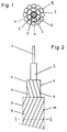
- the optical cable 1 shown in Fig. 1 consists of a Optical waveguide 2, the inside of a small fiber optic tube made of stainless steel and as a reinforcement serving first layer 3 with an excess length of at least 0.5 ⁇ , preferably over 3 ⁇ , is introduced so that the optical waveguide 2 also after a tensile load or thermal expansion of the cable 1 remains fully functional.
- the cavity 4 is between the optical fiber 2 and the first Layer 3 forming optical waveguide tubes for prevention a possible intrusion e.g. of condensed water or of moisture, which is the transferability of the optical waveguide 2 due to undesired reflection effects severely impair or prevent filled with a gel.
- the wall thickness of the first Layer 3 forming optical fiber tube which at the present cable preferably in the range of 0.05 can be up to 0.3 mm, is 0.1 mm, the diameter the optical fiber tube forming the first layer 3, preferably in the present cable can be in the range of 0.8 to 3 mm, 0.9 mm.
- the fiber optic tube 3 is characterized by a minimum bending radius from 15 mm.
- first layer 3 forms the first wire layer second layer 5 of six diameters Stainless steel wires 6 in a first lay direction with a Impact angle of 22.5 ° and the second wire layer forming third layer 7 of twelve diameters Stainless steel wires 8 in the opposite direction to the first lay direction Impact direction with an impact angle of 21.2 ° upset.
- the first layer 5 made of stainless steel wires 6 and the second layer 7 made of stainless steel wires 8 all have the same diameter of 0.8 mm.
- the minimum bending radius the cable 1 is 19 mm, so that Cable 1 has a very high kink resistance and a high one Has flexibility.
- the maximum tensile strength of the Cable 1 is 6000 N and the maximum transverse load capacity at 400,000 N / m, so that the cable 1 in all directions can withstand extreme loads. Especially when temporarily laying the optical cable 1 in free field is also the high impact resistance of special advantage.
- the opposite directions of impact are 9 and 10 serving as the second and third layers 5 and 7 stranded first and second wire layers schematically shown.
- resulting high flexibility of the cable 1 becomes one Torsion of the cable 1 largely prevented and at the same time easy flexibility of the cable 1 in any transverse direction to the cable axis, but the bend of cable 1 becomes more difficult the closer the Bend comes up to the minimum bending radius because due to the tensile stress on the stainless steel wires on the Outside of the bend and the compressive stress of the same on the inside of the bend with increasing tension and Compressive stress the flexibility of the cable 1 decreases, which is particularly the case for the third layer 7 second wire layer applies.
- a kink in the cable 1 is by the two in the opposite direction stranded wire layers 5 and 7 practically completely prevented.
- the term "kink resistance" is based on the DIN standard EN 187000 referenced.
- Fig. 1 1 When using the optical cable shown in Fig. 1 1 as field cable for field cables for temporary Connection of non-stationary intended for data exchange Transceiver stations or field phones can the cable 1 if necessary also under tension e.g. be led over streets because the cable 1 for it sufficient tensile strength, sufficient Impact resistance and also sufficient cross-loading capacity has, so that even heavy vehicles over the Can drive cables. Because field cables have all sorts Obstacles must be passed, e.g. over terrain, on which are heavy animals, of course, at any time can step on the field cable, or e.g. around corners or piles or rods with a relatively small radius of curvature, is the high kink resistance of cable 1 from very special advantage.
- the optical cable 1 used as a field cable Due to the cumulative especially good tensile strength properties as well as lateral pressure resistance and high flexibility very high kink resistance of the cable 1, it is even possible the optical cable 1 used as a field cable to stretch the floor, i.e. in the air. That as a field cable Cable 1 used can be laid easily because there is hardly any possibility of damage Needs to be taken into account, which is a very ensures quick and inexpensive temporary installation is. Since the optical cable 1 is a relative has a small diameter of 4.1 mm, a relative long cable from e.g. approx. 500 m length by hand, preferably on a small cable reel, easily to the next Are transported or carried, so that the temporary laying even in rough terrain can be done easily. Due to the high flexibility of the optical cable 1 is constantly being used again no problem with the same cable.
Landscapes
- Physics & Mathematics (AREA)
- General Physics & Mathematics (AREA)
- Optics & Photonics (AREA)
- Engineering & Computer Science (AREA)
- Manufacturing & Machinery (AREA)
- Communication Cables (AREA)
- Insulated Conductors (AREA)
- Light Guides In General And Applications Therefor (AREA)
- Resistance Heating (AREA)
Applications Claiming Priority (3)
| Application Number | Priority Date | Filing Date | Title |
|---|---|---|---|
| CH1519/96 | 1996-06-18 | ||
| CH01519/96A CH689358A5 (de) | 1996-06-18 | 1996-06-18 | Optisches Kabel mit Armierungsmitteln und Verwendung desselben. |
| CH151996 | 1996-06-18 |
Publications (3)
| Publication Number | Publication Date |
|---|---|
| EP0816885A2 true EP0816885A2 (fr) | 1998-01-07 |
| EP0816885A3 EP0816885A3 (fr) | 1998-09-16 |
| EP0816885B1 EP0816885B1 (fr) | 2001-10-31 |
Family
ID=4212343
Family Applications (1)
| Application Number | Title | Priority Date | Filing Date |
|---|---|---|---|
| EP97109340A Expired - Lifetime EP0816885B1 (fr) | 1996-06-18 | 1997-06-10 | Câble optique avec armature et son utilisation |
Country Status (5)
| Country | Link |
|---|---|
| EP (1) | EP0816885B1 (fr) |
| AT (1) | ATE208051T1 (fr) |
| CH (1) | CH689358A5 (fr) |
| DE (1) | DE59705143D1 (fr) |
| DK (1) | DK0816885T3 (fr) |
Cited By (4)
| Publication number | Priority date | Publication date | Assignee | Title |
|---|---|---|---|---|
| EP1717620A1 (fr) * | 2005-04-27 | 2006-11-02 | Run Chi Hsu | Câble optique anti-torsion |
| CN108802936A (zh) * | 2018-07-05 | 2018-11-13 | 佛山市易轩软件科技有限公司 | 一种耐辐射耐弯加强型光缆 |
| EP3674761A1 (fr) * | 2018-12-31 | 2020-07-01 | Sterlite Technologies Limited | Câble à fibre optique unitube |
| CN113644102A (zh) * | 2021-08-10 | 2021-11-12 | 京东方科技集团股份有限公司 | 显示模组及其制备方法、显示装置 |
Citations (11)
| Publication number | Priority date | Publication date | Assignee | Title |
|---|---|---|---|---|
| DE2628070B1 (de) * | 1976-06-21 | 1977-08-11 | Siemens Ag | Einadriges optisches Kabel |
| GB2010528A (en) * | 1977-12-16 | 1979-06-27 | Post Office | Underwater Cable |
| EP0023154A1 (fr) * | 1979-07-23 | 1981-01-28 | PIRELLI GENERAL plc | Câble de fibres optiques et procédé pour sa fabrication |
| GB2105865A (en) * | 1982-07-09 | 1983-03-30 | Philips Nv | Optical communication cable having a light wave guide and a tensile secondary coating |
| FR2559592A1 (fr) * | 1984-02-10 | 1985-08-16 | Cables Electro Telecommunicati | Cable optique monofibre et son utilisation au guidage d'un engin volant |
| US4606604A (en) * | 1984-05-16 | 1986-08-19 | Optelecom, Inc. | Optical fiber submarine cable and method of making |
| EP0405716A2 (fr) * | 1989-06-29 | 1991-01-02 | AT&T Corp. | Câble bobinable à couple balancé et méthode de fabrication |
| EP0405851A1 (fr) * | 1989-06-30 | 1991-01-02 | AT&T Corp. | Câble ayant une couche d'armure non mÀ©tallique |
| EP0541198A1 (fr) * | 1991-10-30 | 1993-05-12 | AT&T Corp. | Câble résistant à la vapeur par exemple câble à fibres optiques résistant à la vapeur |
| DE4228272A1 (de) * | 1992-08-26 | 1994-03-03 | Siemens Ag | Optisches Kabel mit einer Bewehrung |
| DE4337180A1 (de) * | 1993-10-30 | 1995-06-14 | Felten & Guilleaume Energie | Mehradrige flexible Starkstromleitung mit integrierten Lichtwellenleitern (LWL) |
-
1996
- 1996-06-18 CH CH01519/96A patent/CH689358A5/de not_active IP Right Cessation
-
1997
- 1997-06-10 AT AT97109340T patent/ATE208051T1/de not_active IP Right Cessation
- 1997-06-10 DK DK97109340T patent/DK0816885T3/da active
- 1997-06-10 EP EP97109340A patent/EP0816885B1/fr not_active Expired - Lifetime
- 1997-06-10 DE DE59705143T patent/DE59705143D1/de not_active Expired - Lifetime
Patent Citations (11)
| Publication number | Priority date | Publication date | Assignee | Title |
|---|---|---|---|---|
| DE2628070B1 (de) * | 1976-06-21 | 1977-08-11 | Siemens Ag | Einadriges optisches Kabel |
| GB2010528A (en) * | 1977-12-16 | 1979-06-27 | Post Office | Underwater Cable |
| EP0023154A1 (fr) * | 1979-07-23 | 1981-01-28 | PIRELLI GENERAL plc | Câble de fibres optiques et procédé pour sa fabrication |
| GB2105865A (en) * | 1982-07-09 | 1983-03-30 | Philips Nv | Optical communication cable having a light wave guide and a tensile secondary coating |
| FR2559592A1 (fr) * | 1984-02-10 | 1985-08-16 | Cables Electro Telecommunicati | Cable optique monofibre et son utilisation au guidage d'un engin volant |
| US4606604A (en) * | 1984-05-16 | 1986-08-19 | Optelecom, Inc. | Optical fiber submarine cable and method of making |
| EP0405716A2 (fr) * | 1989-06-29 | 1991-01-02 | AT&T Corp. | Câble bobinable à couple balancé et méthode de fabrication |
| EP0405851A1 (fr) * | 1989-06-30 | 1991-01-02 | AT&T Corp. | Câble ayant une couche d'armure non mÀ©tallique |
| EP0541198A1 (fr) * | 1991-10-30 | 1993-05-12 | AT&T Corp. | Câble résistant à la vapeur par exemple câble à fibres optiques résistant à la vapeur |
| DE4228272A1 (de) * | 1992-08-26 | 1994-03-03 | Siemens Ag | Optisches Kabel mit einer Bewehrung |
| DE4337180A1 (de) * | 1993-10-30 | 1995-06-14 | Felten & Guilleaume Energie | Mehradrige flexible Starkstromleitung mit integrierten Lichtwellenleitern (LWL) |
Cited By (7)
| Publication number | Priority date | Publication date | Assignee | Title |
|---|---|---|---|---|
| EP1717620A1 (fr) * | 2005-04-27 | 2006-11-02 | Run Chi Hsu | Câble optique anti-torsion |
| CN108802936A (zh) * | 2018-07-05 | 2018-11-13 | 佛山市易轩软件科技有限公司 | 一种耐辐射耐弯加强型光缆 |
| CN111505779A (zh) * | 2018-07-05 | 2020-08-07 | 杭州富通通信技术股份有限公司 | 耐辐射耐弯加强型光缆 |
| CN111505779B (zh) * | 2018-07-05 | 2021-06-25 | 杭州富通通信技术股份有限公司 | 耐辐射耐弯加强型光缆 |
| EP3674761A1 (fr) * | 2018-12-31 | 2020-07-01 | Sterlite Technologies Limited | Câble à fibre optique unitube |
| CN113644102A (zh) * | 2021-08-10 | 2021-11-12 | 京东方科技集团股份有限公司 | 显示模组及其制备方法、显示装置 |
| CN113644102B (zh) * | 2021-08-10 | 2024-03-15 | 京东方科技集团股份有限公司 | 显示模组及其制备方法、显示装置 |
Also Published As
| Publication number | Publication date |
|---|---|
| DE59705143D1 (de) | 2001-12-06 |
| ATE208051T1 (de) | 2001-11-15 |
| EP0816885A3 (fr) | 1998-09-16 |
| EP0816885B1 (fr) | 2001-10-31 |
| CH689358A5 (de) | 1999-03-15 |
| DK0816885T3 (da) | 2003-04-14 |
Similar Documents
| Publication | Publication Date | Title |
|---|---|---|
| DE2820510C2 (de) | Elektrischer Freileiter | |
| EP0393013B1 (fr) | Faisceau d'élément de tension constitué de membres de contrainte | |
| DE3318233C2 (de) | Optisches Kabelelement bzw. Kabel und Verfahren zu seiner Herstellung | |
| DE60037026T2 (de) | Faseroptisches kabel mit verstärkungselement innerhalb einer äusseren umhüllung | |
| EP0479839B1 (fr) | Cable optique avec au moins un conducteur en fibre optique | |
| DE2347408B2 (de) | Optischer Faserstrang | |
| DE3118172C2 (fr) | ||
| DE2600100A1 (de) | Optischer leiter | |
| CH656970A5 (de) | Hochflexibles isoliertes elektrisches kabel, verfahren zu seiner herstellung und verwendung des kabels. | |
| EP0110445A1 (fr) | Gaine pour des guides d'ondes lumineuses | |
| DE3643886A1 (de) | Nachrichtenkabel mit lichtwellenleitern | |
| DE2815563A1 (de) | Optisches kabel | |
| DE2817045A1 (de) | Optisches kabel | |
| DE2511019C2 (de) | Grundelement zum Aufbau optischer Kabel | |
| DE2948757A1 (de) | Verstaerkter optischer faserleiter und optisches faserkabel | |
| DE102017101646A1 (de) | Längselement, insbesondere für ein Zug- oder Tragmittel | |
| EP0072594A2 (fr) | Câble de télécommunication optique | |
| EP0816885B1 (fr) | Câble optique avec armature et son utilisation | |
| WO2011035450A2 (fr) | Câble électro-optique | |
| EP0527311B1 (fr) | Dispositif de guidage de câble avec au moins un tuyau de guidage de câble | |
| EP1220235B1 (fr) | Câble pour ligne aérienne pour lignes aériennes à haute tension | |
| DE3606589C2 (fr) | ||
| DE69737577T2 (de) | Faseroptisches Kabel mit erhöhtem Quetschwiderstand | |
| DE19726731C1 (de) | Sensorkabel | |
| EP3655582A1 (fr) | Section de câble et procédé d'épissurage d'un câble formant un câble de transport des personnes |
Legal Events
| Date | Code | Title | Description |
|---|---|---|---|
| PUAI | Public reference made under article 153(3) epc to a published international application that has entered the european phase |
Free format text: ORIGINAL CODE: 0009012 |
|
| AK | Designated contracting states |
Kind code of ref document: A2 Designated state(s): AT BE DE DK FR GB IT LU NL SE |
|
| PUAL | Search report despatched |
Free format text: ORIGINAL CODE: 0009013 |
|
| AK | Designated contracting states |
Kind code of ref document: A3 Designated state(s): AT BE CH DE DK ES FI FR GB GR IE IT LI LU MC NL PT SE |
|
| 17P | Request for examination filed |
Effective date: 19980918 |
|
| 17Q | First examination report despatched |
Effective date: 19981110 |
|
| AKX | Designation fees paid |
Free format text: AT BE DE DK FR GB IT LU NL SE |
|
| RBV | Designated contracting states (corrected) |
Designated state(s): AT BE DE DK FR GB IT LU NL SE |
|
| GRAG | Despatch of communication of intention to grant |
Free format text: ORIGINAL CODE: EPIDOS AGRA |
|
| GRAG | Despatch of communication of intention to grant |
Free format text: ORIGINAL CODE: EPIDOS AGRA |
|
| APAB | Appeal dossier modified |
Free format text: ORIGINAL CODE: EPIDOS NOAPE |
|
| APAD | Appeal reference recorded |
Free format text: ORIGINAL CODE: EPIDOS REFNE |
|
| APAB | Appeal dossier modified |
Free format text: ORIGINAL CODE: EPIDOS NOAPE |
|
| GRAG | Despatch of communication of intention to grant |
Free format text: ORIGINAL CODE: EPIDOS AGRA |
|
| GRAH | Despatch of communication of intention to grant a patent |
Free format text: ORIGINAL CODE: EPIDOS IGRA |
|
| GRAH | Despatch of communication of intention to grant a patent |
Free format text: ORIGINAL CODE: EPIDOS IGRA |
|
| GRAA | (expected) grant |
Free format text: ORIGINAL CODE: 0009210 |
|
| AK | Designated contracting states |
Kind code of ref document: B1 Designated state(s): AT BE DE DK FR GB IT LU NL SE |
|
| REF | Corresponds to: |
Ref document number: 208051 Country of ref document: AT Date of ref document: 20011115 Kind code of ref document: T |
|
| GBT | Gb: translation of ep patent filed (gb section 77(6)(a)/1977) |
Effective date: 20011031 |
|
| REF | Corresponds to: |
Ref document number: 59705143 Country of ref document: DE Date of ref document: 20011206 |
|
| REG | Reference to a national code |
Ref country code: GB Ref legal event code: IF02 |
|
| PLBE | No opposition filed within time limit |
Free format text: ORIGINAL CODE: 0009261 |
|
| STAA | Information on the status of an ep patent application or granted ep patent |
Free format text: STATUS: NO OPPOSITION FILED WITHIN TIME LIMIT |
|
| 26N | No opposition filed | ||
| REG | Reference to a national code |
Ref country code: DK Ref legal event code: T3 |
|
| APAH | Appeal reference modified |
Free format text: ORIGINAL CODE: EPIDOSCREFNO |
|
| PGFP | Annual fee paid to national office [announced via postgrant information from national office to epo] |
Ref country code: LU Payment date: 20100602 Year of fee payment: 14 |
|
| PGFP | Annual fee paid to national office [announced via postgrant information from national office to epo] |
Ref country code: IT Payment date: 20100626 Year of fee payment: 14 Ref country code: AT Payment date: 20100618 Year of fee payment: 14 |
|
| PGFP | Annual fee paid to national office [announced via postgrant information from national office to epo] |
Ref country code: SE Payment date: 20100512 Year of fee payment: 14 Ref country code: GB Payment date: 20100512 Year of fee payment: 14 |
|
| PGFP | Annual fee paid to national office [announced via postgrant information from national office to epo] |
Ref country code: BE Payment date: 20110114 Year of fee payment: 14 |
|
| BERE | Be: lapsed |
Owner name: *BRUGG TELECOM A.G. Effective date: 20110630 |
|
| REG | Reference to a national code |
Ref country code: SE Ref legal event code: EUG |
|
| GBPC | Gb: european patent ceased through non-payment of renewal fee |
Effective date: 20110610 |
|
| PG25 | Lapsed in a contracting state [announced via postgrant information from national office to epo] |
Ref country code: IT Free format text: LAPSE BECAUSE OF NON-PAYMENT OF DUE FEES Effective date: 20110610 Ref country code: AT Free format text: LAPSE BECAUSE OF NON-PAYMENT OF DUE FEES Effective date: 20110610 |
|
| REG | Reference to a national code |
Ref country code: AT Ref legal event code: MM01 Ref document number: 208051 Country of ref document: AT Kind code of ref document: T Effective date: 20110610 |
|
| PG25 | Lapsed in a contracting state [announced via postgrant information from national office to epo] |
Ref country code: BE Free format text: LAPSE BECAUSE OF NON-PAYMENT OF DUE FEES Effective date: 20110630 |
|
| PG25 | Lapsed in a contracting state [announced via postgrant information from national office to epo] |
Ref country code: GB Free format text: LAPSE BECAUSE OF NON-PAYMENT OF DUE FEES Effective date: 20110610 |
|
| PG25 | Lapsed in a contracting state [announced via postgrant information from national office to epo] |
Ref country code: SE Free format text: LAPSE BECAUSE OF NON-PAYMENT OF DUE FEES Effective date: 20110611 |
|
| PG25 | Lapsed in a contracting state [announced via postgrant information from national office to epo] |
Ref country code: LU Free format text: LAPSE BECAUSE OF NON-PAYMENT OF DUE FEES Effective date: 20110610 |
|
| REG | Reference to a national code |
Ref country code: FR Ref legal event code: PLFP Year of fee payment: 20 |
|
| PGFP | Annual fee paid to national office [announced via postgrant information from national office to epo] |
Ref country code: FR Payment date: 20160523 Year of fee payment: 20 Ref country code: DK Payment date: 20160610 Year of fee payment: 20 Ref country code: NL Payment date: 20160531 Year of fee payment: 20 |
|
| PGFP | Annual fee paid to national office [announced via postgrant information from national office to epo] |
Ref country code: DE Payment date: 20160804 Year of fee payment: 20 |
|
| REG | Reference to a national code |
Ref country code: DE Ref legal event code: R071 Ref document number: 59705143 Country of ref document: DE |
|
| REG | Reference to a national code |
Ref country code: DK Ref legal event code: EUP Effective date: 20170610 |
|
| REG | Reference to a national code |
Ref country code: NL Ref legal event code: MK Effective date: 20170609 |