EP0816783A2 - Abtausteuerverfahren- und Vorrichtung - Google Patents
Abtausteuerverfahren- und Vorrichtung Download PDFInfo
- Publication number
- EP0816783A2 EP0816783A2 EP97304532A EP97304532A EP0816783A2 EP 0816783 A2 EP0816783 A2 EP 0816783A2 EP 97304532 A EP97304532 A EP 97304532A EP 97304532 A EP97304532 A EP 97304532A EP 0816783 A2 EP0816783 A2 EP 0816783A2
- Authority
- EP
- European Patent Office
- Prior art keywords
- evaporator
- refrigerant
- superheat
- temperature
- defrosting
- Prior art date
- Legal status (The legal status is an assumption and is not a legal conclusion. Google has not performed a legal analysis and makes no representation as to the accuracy of the status listed.)
- Withdrawn
Links
- 238000000034 method Methods 0.000 title claims description 21
- 239000003507 refrigerant Substances 0.000 claims abstract description 56
- 239000007788 liquid Substances 0.000 claims abstract description 33
- 238000010257 thawing Methods 0.000 claims abstract description 28
- 230000004044 response Effects 0.000 claims description 9
- 238000012546 transfer Methods 0.000 claims description 7
- 230000000977 initiatory effect Effects 0.000 claims description 6
- 230000001276 controlling effect Effects 0.000 claims 3
- 230000001105 regulatory effect Effects 0.000 claims 2
- 230000001960 triggered effect Effects 0.000 abstract description 2
- 239000003570 air Substances 0.000 description 21
- 239000012530 fluid Substances 0.000 description 14
- 238000005057 refrigeration Methods 0.000 description 14
- 238000010438 heat treatment Methods 0.000 description 6
- 239000012080 ambient air Substances 0.000 description 5
- 238000001514 detection method Methods 0.000 description 5
- 238000004891 communication Methods 0.000 description 4
- 239000000203 mixture Substances 0.000 description 4
- 230000035939 shock Effects 0.000 description 4
- 238000009835 boiling Methods 0.000 description 3
- 230000001419 dependent effect Effects 0.000 description 3
- 230000000694 effects Effects 0.000 description 3
- 238000007796 conventional method Methods 0.000 description 2
- 238000012937 correction Methods 0.000 description 2
- 238000010586 diagram Methods 0.000 description 2
- 238000006073 displacement reaction Methods 0.000 description 2
- 238000005485 electric heating Methods 0.000 description 2
- 230000009467 reduction Effects 0.000 description 2
- 239000000126 substance Substances 0.000 description 2
- XLYOFNOQVPJJNP-UHFFFAOYSA-N water Substances O XLYOFNOQVPJJNP-UHFFFAOYSA-N 0.000 description 2
- RYGMFSIKBFXOCR-UHFFFAOYSA-N Copper Chemical compound [Cu] RYGMFSIKBFXOCR-UHFFFAOYSA-N 0.000 description 1
- 230000008901 benefit Effects 0.000 description 1
- 230000000903 blocking effect Effects 0.000 description 1
- 230000008859 change Effects 0.000 description 1
- 229910052802 copper Inorganic materials 0.000 description 1
- 239000010949 copper Substances 0.000 description 1
- 230000008878 coupling Effects 0.000 description 1
- 238000010168 coupling process Methods 0.000 description 1
- 238000005859 coupling reaction Methods 0.000 description 1
- 238000005265 energy consumption Methods 0.000 description 1
- 238000001704 evaporation Methods 0.000 description 1
- 230000008020 evaporation Effects 0.000 description 1
- 230000006870 function Effects 0.000 description 1
- 230000001771 impaired effect Effects 0.000 description 1
- 239000000463 material Substances 0.000 description 1
- 238000005259 measurement Methods 0.000 description 1
- 230000008018 melting Effects 0.000 description 1
- 238000002844 melting Methods 0.000 description 1
- 239000002184 metal Substances 0.000 description 1
- 229910052751 metal Inorganic materials 0.000 description 1
- 229910001092 metal group alloy Inorganic materials 0.000 description 1
- 238000012544 monitoring process Methods 0.000 description 1
- 229920006395 saturated elastomer Polymers 0.000 description 1
- 238000007789 sealing Methods 0.000 description 1
- 238000009834 vaporization Methods 0.000 description 1
Images


Classifications
-
- F—MECHANICAL ENGINEERING; LIGHTING; HEATING; WEAPONS; BLASTING
- F25—REFRIGERATION OR COOLING; COMBINED HEATING AND REFRIGERATION SYSTEMS; HEAT PUMP SYSTEMS; MANUFACTURE OR STORAGE OF ICE; LIQUEFACTION SOLIDIFICATION OF GASES
- F25D—REFRIGERATORS; COLD ROOMS; ICE-BOXES; COOLING OR FREEZING APPARATUS NOT OTHERWISE PROVIDED FOR
- F25D21/00—Defrosting; Preventing frosting; Removing condensed or defrost water
- F25D21/002—Defroster control
-
- F—MECHANICAL ENGINEERING; LIGHTING; HEATING; WEAPONS; BLASTING
- F25—REFRIGERATION OR COOLING; COMBINED HEATING AND REFRIGERATION SYSTEMS; HEAT PUMP SYSTEMS; MANUFACTURE OR STORAGE OF ICE; LIQUEFACTION SOLIDIFICATION OF GASES
- F25B—REFRIGERATION MACHINES, PLANTS OR SYSTEMS; COMBINED HEATING AND REFRIGERATION SYSTEMS; HEAT PUMP SYSTEMS
- F25B41/00—Fluid-circulation arrangements
- F25B41/30—Expansion means; Dispositions thereof
- F25B41/31—Expansion valves
- F25B41/34—Expansion valves with the valve member being actuated by electric means, e.g. by piezoelectric actuators
- F25B41/345—Expansion valves with the valve member being actuated by electric means, e.g. by piezoelectric actuators by solenoids
- F25B41/347—Expansion valves with the valve member being actuated by electric means, e.g. by piezoelectric actuators by solenoids with the valve member being opened and closed cyclically, e.g. with pulse width modulation
-
- F—MECHANICAL ENGINEERING; LIGHTING; HEATING; WEAPONS; BLASTING
- F25—REFRIGERATION OR COOLING; COMBINED HEATING AND REFRIGERATION SYSTEMS; HEAT PUMP SYSTEMS; MANUFACTURE OR STORAGE OF ICE; LIQUEFACTION SOLIDIFICATION OF GASES
- F25B—REFRIGERATION MACHINES, PLANTS OR SYSTEMS; COMBINED HEATING AND REFRIGERATION SYSTEMS; HEAT PUMP SYSTEMS
- F25B2600/00—Control issues
- F25B2600/21—Refrigerant outlet evaporator temperature
-
- F—MECHANICAL ENGINEERING; LIGHTING; HEATING; WEAPONS; BLASTING
- F25—REFRIGERATION OR COOLING; COMBINED HEATING AND REFRIGERATION SYSTEMS; HEAT PUMP SYSTEMS; MANUFACTURE OR STORAGE OF ICE; LIQUEFACTION SOLIDIFICATION OF GASES
- F25B—REFRIGERATION MACHINES, PLANTS OR SYSTEMS; COMBINED HEATING AND REFRIGERATION SYSTEMS; HEAT PUMP SYSTEMS
- F25B41/00—Fluid-circulation arrangements
- F25B41/30—Expansion means; Dispositions thereof
- F25B41/31—Expansion valves
- F25B41/33—Expansion valves with the valve member being actuated by the fluid pressure, e.g. by the pressure of the refrigerant
- F25B41/335—Expansion valves with the valve member being actuated by the fluid pressure, e.g. by the pressure of the refrigerant via diaphragms
-
- Y—GENERAL TAGGING OF NEW TECHNOLOGICAL DEVELOPMENTS; GENERAL TAGGING OF CROSS-SECTIONAL TECHNOLOGIES SPANNING OVER SEVERAL SECTIONS OF THE IPC; TECHNICAL SUBJECTS COVERED BY FORMER USPC CROSS-REFERENCE ART COLLECTIONS [XRACs] AND DIGESTS
- Y02—TECHNOLOGIES OR APPLICATIONS FOR MITIGATION OR ADAPTATION AGAINST CLIMATE CHANGE
- Y02B—CLIMATE CHANGE MITIGATION TECHNOLOGIES RELATED TO BUILDINGS, e.g. HOUSING, HOUSE APPLIANCES OR RELATED END-USER APPLICATIONS
- Y02B30/00—Energy efficient heating, ventilation or air conditioning [HVAC]
- Y02B30/70—Efficient control or regulation technologies, e.g. for control of refrigerant flow, motor or heating
Definitions
- the present invention relates to a method and apparatus for controlling defrosting of an evaporator in a heat transfer system, particularly but not exclusively in a refrigeration system in which there is a forced airflow over the evaporator.
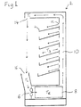
- FIG 1 shows in cross-section a refrigerated display cabinet 2, which is one example of such a refrigeration system.
- the cabinet 2 has a number of shelves for displaying chilled food or drinks.
- the cabinet 2 is open at the front (to the left in Figure 1) to allow shoppers easy access to the contents of the shelves 4.
- the contents are cooled by air blown by a fan 6 over an evaporator 8 of the refrigeration system, which cools the air.
- the air leaves the evaporator 8 is forced up a duct 10 and escapes through small vents 12 so that some of the air flows over the contents of the shelves 4.
- the ambient air includes water vapour which condenses and freezes on the evaporator 8 to form frost.
- the frost impedes the passage of air over the evaporator 8 and reduces the efficiency of heat exchange between the evaporator 8 and the air. If the frost is allowed to build up, the rate of airflow will be reduced sufficiently to prevent the air curtain from forming and the internal temperature of the cabinet will rise. Furthermore, the efficiency of the refrigeration system will be reduced, leading to higher running costs.
- gas defrost method gas is passed through the evaporator so as to warm it and melt the frost.
- the gas may be directed from the outlet of the compressor of the refrigeration system through the evaporator, so that the evaporator 8 acts temporarily as a condenser and the refrigeration cycle acts in reverse to release heat from the evaporator 8. This is known as the "hot gas" method.
- the gas may be taken from the top of the receiver of the refrigeration system, in which the refrigerant is stored before passing through the expansion valve. This is known as the "cool gas” method, since the refrigerant has passed through the condenser and is cool.
- the air temperature inside the cabinet 2 rises above the normal storage temperature, and the contents are subject to "temperature shock".
- the effect of this temperature shock is to reduce the shelf life of perishable goods.
- the defrost cycle consumes a significant amount of energy, typically around 10% of the total energy used in refrigeration.
- a defrost is initiated periodically at intervals sufficiently short to prevent the evaporator 8 from frosting up completely and thereby blocking the flow of air, even at the maximum absolute humidity for which the cabinet 2 is designed. This interval is typically between 6 and 8 hours. However, when the absolute humidity is less than its maximum, defrosts occur more frequently than required.
- the document EP-A-0 494 785 describes a defrost control system using a temperature sensor within an evaporator unit to determine when defrost is required.
- apparatus According to one aspect of the present invention, there is provided apparatus according to claim 1. According to another aspect of the present invention, there is provided a method according to claim 13.
- An advantage of the invention is that the superheat of refrigerant at the evaporator outlet is used to determine when defrosting is required.
- the superheat of the refrigerant provides a more direct measurement of the efficiency of the evaporator than the methods of the state of the art, since if the superheat falls below a minimum level, this indicates that insufficient heat is absorbed by the evaporator, which may be a result of frost on the evaporator.
- the superheat itself may be measured, or a liquid sensor may be used to determine whether liquid refrigerant is present at the outlet, indicating that the refrigerant has no superheat.
- a liquid sensor is preferred, since the refrigerant leaving the evaporator should have as low a superheat as possible, for efficient use of the evaporator, but liquid should be prevented from entering the compressor.
- the liquid sensor is suitable for detecting a point at which both criteria are satisfied.
- an expansion valve through which refrigerant flows into the evaporator is controlled according to a sensed temperature of the thermal load of the heat transfer system.
- the control is overridden and the flow through the expansion valve is reduced when the degree of superheat of refrigerant at the evaporator outlet falls below a predetermined level or a predetermined proportion of liquid is detected at the outlet. Defrost of the evaporator is initiated when the overrides exceed a predetermined level.
- defrost is initiated when the evaporator is no longer able continuously to maintain the temperature of the thermal load within a desired range without causing the superheat of the refrigerant at the outlet to fall below a minimum level or liquid to appear at the outlet.
- This situation is a direct result of the reduction in efficiency of the evaporator due to frost.
- defrost is only initiated when it is required to overcome this reduction in efficiency.
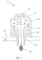
- Figure 2 shows part of the refrigeration system, comprising an expansion valve 18 through which refrigerant at high pressure from the condenser is admitted into the evaporator 8 at low pressure.
- the expansion valve 18 is controlled by an electrical signal on a line 20 connected to a control circuit 22.
- the control circuit 22 controls the time periods for which the expansion valve 18 is opened and closed within a continuously repeated cycle.
- the cycle is typically one of six or eight seconds duration, the valve being pulsed open once in each cycle for a period determined by the required flow rate.
- Other types of electrically controlled valve may be used, such as a stepper motor valve.
- the refrigerant As the refrigerant passes at low pressure through the evaporator 8, it evaporates and absorbs heat from the air surrounding the evaporator 8 as the latent heat of evaporation.
- the evaporated refrigerant passes through an outlet 24 of the evaporator 8 and is returned through a suction pipe to a compressor 26 which compresses the refrigerant to high pressure and outputs it to the condenser (not shown), where the refrigerant condenses and releases the latent heat.
- a temperature sensor 28 senses the temperature outside the evaporator 8.
- the temperature sensor 28 may be positioned to sense the external temperature T E around the evaporator 8, the "air off” temperature T 1 of air leaving the duct 10, the "air on” temperature T 2 of air entering the inlet 16 or the temperature T 3 of the storage area of the cabinet.
- the temperature sensor 28 generates an electrical signal representing the sensed temperature on the line 30, which is input to the control circuit 22.
- the control circuit 22 sets the duty ratio of the signal on the line 20 according to the relationship between the temperature sensed by the temperature sensor 28 and a desired temperature range programmed in the control circuit 22. If the sensed temperature is below the desired range, the expansion valve 18 will be open for a shorter period, so as to reduce the flow of refrigerant to the evaporator 8, whereas when the sensed temperature is above the desired range, the expansion valve 18 is open for a longer period so as to increase the flow of refrigerant through the evaporator 8.
- liquid refrigerant will be present at the outlet 24 of the evaporator 8 and may subsequently enter and damage the compressor 26.
- a superheat sensor 32 is provided at the outlet 24 of the evaporator 8.
- the superheat sensor detects the level of superheat of the refrigerant, which is the temperature difference by which the temperature of the refrigerant exceeds the boiling point of the refrigerant at the outlet pressure. If the superheat is zero, the refrigerant is at boiling point and there will be liquid refrigerant present at the outlet 24.
- the superheat sensor 32 outputs an electrical signal on a line 34 to the control circuit 22, whereby the control circuit 22 detects whether the degree of superheat has fallen below a predetermined safe level. In that case, the control circuit 22 enters an "override" condition in which it controls the expansion valve 18 to reduce the flow of refrigerant through the evaporator 8 until the detected degree of superheat rises above a predetermined level, which may be the same as or different from the minimum level.
- the device comprises a body 60 having a portion 61 which is threaded so as to permit the device to be mounted in a fluid-sealing manner in the wall 25' of the suction pipe 25 at the outlet 24 of the evaporator 8.
- the body 60 has an internal chamber 63 which is in open communication with the fluid flowing through the pipe 25 at the end having the threaded portion 61.
- a movable member in the form of a flexible diaphragm 62 is mounted within the chamber 63 on support elements 64 and 66.
- the upperside of the diaphragm 62 in the drawing is in open communication with the fluid within the chamber 63, via respective apertures 65, 67 in the support elements 64, 66. This upperside of the diaphragm is thereby subject to the vapour pressure of the fluid at the outlet 24 of the evaporator.
- the lower side of the diaphragm is isolated from the vapour pressure of the refrigerant fluid within the chamber 63, and is coupled instead to a container in the form of a phial 68 containing a quantity of liquid, as indicated by the horizontal shading in the drawing.
- the coupling forms a closed sub-chamber 69 containing a saturated vapour of the liquid within the phial.
- the phial is fixed in its location with respect to the body of the sensor device and is disposed substantially externally of the body.
- the phial is surrounded by the refrigerant fluid flow, its liquid content acquires the temperature of that fluid, and a vapour pressure corresponding to that temperature is exerted on the lower side of the diaphragm by the vapour within the sub-chamber 69.
- a difference in the respective vapour pressures exerted on the opposite, upper and lower surfaces of the diaphragm 62 determines a vertical displacement of the diaphragm which is related to the amount of superheat.
- a detector for the diaphragm displacement is housed in the support element 66.
- the detector comprises an elongate linearly-movable member 70 coupled to the diaphragm, and a position sensor 71 for sensing the position of the member 70.
- the position sensor 71 thus outputs an electrical signal related to the sensed superheat, the signal being led out at the top end of the body 60 through a FusiteTM connector 72 which provides the necessary pressure seal.
- the output signal is supplied to the control circuit 22 on line 34.
- the liquid in the phial 68 preferably has a composition which is the same as, or very similar to, that of the refrigerant circulated through the evaporator. If the refrigerant is a mixture of substances having different boiling points, the liquid in the phial 68 should substantially match the least volatile component of the mixture, since that component will determine whether there is any superheat in the refrigerant. In both these cases, the vapour pressure exerted on the longer side of the diaphragm 62 will be that required for measuring the superheat. Alternatively, a known substance, different from the refrigerant, may be used for the phial liquid. In that case, a correction needs to be made to the electrical signal output by the position sensor 71.
- the correction is to allow for the relationship between the different vapour pressure-temperature characteristics of the liquid in the phial (which determines the vapour pressure in the sub-chamber 69) and the refrigerant in the evaporator (which determines the vapour pressure in the chamber 63).
- the superheat sensor 32 may comprise a device for detecting the presence of liquid in the flow of refrigerant at the outlet 24.
- a device for detecting the presence of liquid in the flow of refrigerant at the outlet 24 are described in UK patent publication numbers 2,302,725 and 2,308,192. The latter is also incorporated herein by reference.
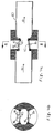
- One example of such a device will now be described with reference to Figures 4a and 4b.
- the device comprises principally a tube 80 and a number of components 84 to 86 mounted on the tube, externally thereof.
- the components consist of a first temperature sensor 85, an electrical heating element 86 mounted adjacent the sensor 85, and a second temperature sensor 84.
- the two temperature sensors 84, 85 are each temperature-dependent resistors or thermistors, whereas the heating element 86 is an electrical resistor.
- the thermistor 85 and heating resistor 86 are mounted side-by-side on a first portion or member 83 of the tube wall.
- the other thermistor 84 is mounted on a second portion or member 82 of the tube wall, diametrically opposing the first portion.
- the tube 80 is made of a material having a good thermal conductivity, preferably a metal or metal alloy. In this embodiment a copper tube is used.
- a fluid which is normally in the gas state flows through the tube 80 in a direction indicated generally by the arrows 81 in Figure 4a.
- Both of the thermistors 84, 85 are responsive to the temperature of the fluid flowing past the members 82, 83.
- the member 82 will acquire substantially the gas temperature and this temperature is sensed by the thermistor 84.
- the member 83 will acquire a temperature higher than the gas temperature due to the heating effect of the resistor 86, and this higher temperature is sensed by the thermistor 85.
- the temperature difference is monitored by a detection means comprising a comparator (not shown).
- the comparator may be incorporated in the apparatus itself, but it is conveniently provided in the control circuit 22.
- the detection means is readily implemented using electronic components with which the skilled person is familiar.
- the outputs of the temperature sensors 84 and 85 may be connected by the line 34 to the control circuit 22.
- the liquid comes into contact with the heated wall portion 83 of a temperature exceeding that of the fluid.
- the effect of this contact is that the liquid immediately vaporises, the heated portion 83 providing the necessary latent heat for the change of state.
- the vaporisation of the liquid is manifest by a rapid or sudden lowering of the temperature of the portion 83, which is detected by the thermistor 85.
- the detection may be achieved by setting a threshold for the output of the comparator: if the output level, corresponding to the temperature difference, falls below the threshold (for example, instantaneously or for a predetermined period), an output signal indicating liquid detection is generated.
- the size of the temperature difference is dependent on the amount of liquid, i.e. the ratio of liquid to gas in the fluid being monitored.
- the threshold for detection it is possible to set the threshold for detection at a level which corresponds to a particular degree of wetness which needs to be checked.
- the two portions 82, 83 of the tube wall on which the sensing components 84 to 86 are mounted, are substantially thermally isolated from each other.
- a defrost heater 36 is arranged around the evaporator 8 and can be electrically heated so as to defrost the evaporator 8.
- the defrost heater 36 is switched on and off under the control of an electrical signal on line 38 from the control circuit 22.
- control circuit 22 determines that the evaporator 8 should be defrosted, it switches on the defrost heater 36 and closes the expansion valve 18 for the duration of the defrost cycle.
- the electric defrost method is used.
- the air or gas methods, or other known methods of defrosting an evaporator may be used under the control of the control circuit 22.
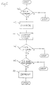
- control circuit 22 determines, by means of the superheat sensor 32, whether the refrigerant at the outlet 24 has less than the predetermined minimum level of superheat. If so, the control circuit 22 reduces the open period of the expansion valve 18 by an amount dependent on the level of superheat below the minimum level or the degree of wetness, at step 42.
- control circuit 22 records the period of time for which the detected superheat was below the minimum level and stores this value in an internal memory, together with the time at which it occurred.
- control circuit 22 determines whether the superheat was below the minimum level for more than a percentage x% of the last y minutes.
- x is between 25 and 40%, and y is 30 minutes.
- control circuit 22 may simply record the number of times the superheat fell below the minimum level in the last y minutes, although this method is less preferred since it is less sensitive.
- the control circuit 22 determines whether more than z hours have elapsed since the last defrost, where z is preferably 6 hours. If so, at step 50, the control circuit 22 initiates defrosting of the evaporator 8. If less than z hours have elapsed since the last defrost, the control circuit 22 ends the algorithm without initiating a defrost.
- defrost is automatically initiated if more than a maximum period, such as 2 days, has elapsed since the last defrost, since there is little incremental gain in defrosting at intervals greater than this maximum period.
- control circuit 22 begins the defrost cycle immediately.
- the defrost cabinet 2 may be one of an array of refrigerated cabinets, such as is used in a supermarket. In that case, there is a maximum number of display cabinets which can be defrosted at any one time, in order to limit the load on the defrosting system. The defrosting of cabinets is therefore coordinated to avoid exceeding this maximum number.
- the hot or cool gas may be distributed from a central plant room to the evaporators of the cabinets to be defrosted.
- the control circuit 22 is connected through a communications network to a defrost controller located in the plant room.
- the defrost controller controls the opening and closing of valves to direct the hot or cool gas to the evaporators selected for defrosting.
- control circuit 22 sends a signal to the remote defrost controller, which adds data representing the refrigerated cabinet 2 to a defrost queue.
- the remote defrost controller defrosts the cabinets in the order of the queue.
- a delay is incurred between entering the cabinet on the defrost queue, at step 50, and defrosting of the evaporator 8.
- the frequency of "overrides”, at which the superheat falls below the minimum level or to zero begins to increase a considerable time before the defrost becomes essential. Therefore, the values of x and y can be set so that, even allowing for the queuing delay, defrosting takes place before the evaporator 8 frosts up completely.
- the hot or cool gas can be supplied through a ring main, separately from the normal supply of refrigerant.
- the control circuit 22 initiates defrost, it opens a valve to connect the evaporator 8 to the ring main.
- the control circuit 22 of each display cabinet may be connected to a communications network so as to coordinate defrosting to avoid exceeding the maximum number of cabinets which are defrosted at any one time.
- the control circuit may initiate defrosting by sending a defrost request signal over the network and open the valve in response to a defrost control signal from the network.
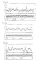
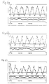
- the evaporator 8 was last defrosted at 15.00 hours on Tuesday.
- the graphs show the degree of superheat, the cabinet temperature T 3 and the evaporator temperature T E as a function of time.
- the minimum superheat level is set at 6°C and the desired cabinet temperature T 3 at 1°C.
- Table 1 below records the time at which overrides occur, the approximate length in minutes of these overrides, and the total period of overrides in the last thirty minutes.
- Graph 6a covers the period from 18.00 hours on Tuesday to 11.00 on Wednesday, while graphs 6b to 6i each cover one hour of a sequence from 09.00 hours to 18.00 hours on Wednesday, excluding from 13.00 to 14.00 hours, for which no data was available. The last two hours of graph 6a are covered by graphs 6b and 6c.
- the control circuit 22 has been in the override state for 9 minutes, which is greater than 25%, of the last 30 minutes. More than 6 hours have elapsed since the last defrost, at 15.00 hours on Tuesday. Therefore, the control circuit 22 reaches step 50 and triggers a defrost by entering the evaporator 8 on the defrost queue. After the defrost has been triggered at step 50, but before defrosting occurs, overrides occur at more or less regular intervals but the cabinet temperature T 3 does not vary significantly from the ideal temperature of 1°C.
- the evaporator 8 is defrosted.
- the defrost cycle should stop as soon as possible after all the ice on the evaporator 8 has melted.
- the temperature T E in the vicinity of the evaporator 8 is measured and the defrost cycle is stopped when the temperature rises above a predetermined level, such as 15°C. If the temperature has not risen above this level after a predetermined period, then the defrost cycle is stopped.
- the evaporator 8 may be isolated from the rest of the system and the pressure within the evaporator is measured. Provided the evaporator contains a mixture of liquid and gaseous refrigerant, the vapour pressure inside the evaporator 8 is used to determine the temperature of the evaporator. When this temperature has risen above a predetermined level, the defrost cycle is stopped. Alternatively, the defrost period is determined by a timer set so as to ensure that all the frost has melted, without causing too great a temperature shock.
- the present invention is also applicable to any heat transfer system in which frequent defrosting of an evaporator 8 is required.
- the present invention is also applicable to freezer display cabinets, blast chillers, blast freezers, air conditioners or heat pumps in which heat is extracted from ambient air or water in a heating system.
- the outlet pressure and temperature may be detected and may be used to calculate the degree of superheat, or a lookup table may be used to determine which values of pressure and temperature correspond to a degree of superheat below the predetermined level.
- Other methods of detecting the presence of liquid in the refrigerant may be used, such as described in the document GB-A-2 157 447, for example.
Applications Claiming Priority (2)
| Application Number | Priority Date | Filing Date | Title |
|---|---|---|---|
| GB9614157A GB2314915B (en) | 1996-07-05 | 1996-07-05 | Defrost control method and apparatus |
| GB9614157 | 1996-07-05 |
Publications (2)
| Publication Number | Publication Date |
|---|---|
| EP0816783A2 true EP0816783A2 (de) | 1998-01-07 |
| EP0816783A3 EP0816783A3 (de) | 1999-11-03 |
Family
ID=10796422
Family Applications (1)
| Application Number | Title | Priority Date | Filing Date |
|---|---|---|---|
| EP97304532A Withdrawn EP0816783A3 (de) | 1996-07-05 | 1997-06-26 | Abtausteuerverfahren- und Vorrichtung |
Country Status (3)
| Country | Link |
|---|---|
| US (1) | US5813242A (de) |
| EP (1) | EP0816783A3 (de) |
| GB (1) | GB2314915B (de) |
Cited By (3)
| Publication number | Priority date | Publication date | Assignee | Title |
|---|---|---|---|---|
| EP0977967A1 (de) * | 1997-04-08 | 2000-02-09 | Heatcraft Inc. | Abtausteuerung für raumkühlanlage |
| EP1225406A2 (de) | 2001-01-18 | 2002-07-24 | JTL Systems Limited | Verfahren und Gerät zur Abtauregelung |
| EP2976584A4 (de) * | 2013-03-21 | 2016-11-02 | Evapco Inc | Verfahren und vorrichtung zur einleitung von spulenentfrosten in einem verdampfer einer kälteanlage |
Families Citing this family (24)
| Publication number | Priority date | Publication date | Assignee | Title |
|---|---|---|---|---|
| CN1343297A (zh) | 1999-01-12 | 2002-04-03 | Xdx有限公司 | 蒸气压缩系统及其方法 |
| US6314747B1 (en) | 1999-01-12 | 2001-11-13 | Xdx, Llc | Vapor compression system and method |
| AU759907B2 (en) | 1999-01-12 | 2003-05-01 | Xdx Inc. | Vapor compression system and method |
| US6185958B1 (en) | 1999-11-02 | 2001-02-13 | Xdx, Llc | Vapor compression system and method |
| GB2348947A (en) * | 1999-04-12 | 2000-10-18 | Jtl Systems Ltd | Defrost control method and apparatus |
| US6505475B1 (en) * | 1999-08-20 | 2003-01-14 | Hudson Technologies Inc. | Method and apparatus for measuring and improving efficiency in refrigeration systems |
| US6260365B1 (en) | 2000-01-07 | 2001-07-17 | Traulsen & Company, Inc. | Control system and related methods for refrigeration and freezer units |
| US6401470B1 (en) | 2000-09-14 | 2002-06-11 | Xdx, Llc | Expansion device for vapor compression system |
| US6393851B1 (en) | 2000-09-14 | 2002-05-28 | Xdx, Llc | Vapor compression system |
| US7147884B2 (en) * | 2001-12-27 | 2006-12-12 | Jones Curt D | Method for making a novelty frozen food product |
| US8463441B2 (en) | 2002-12-09 | 2013-06-11 | Hudson Technologies, Inc. | Method and apparatus for optimizing refrigeration systems |
| WO2005034643A1 (en) * | 2003-10-07 | 2005-04-21 | Dippin' Dots, Inc. | Method of manufacturing particulate ice cream for storage in conventional freezers |
| US7152415B2 (en) * | 2004-03-18 | 2006-12-26 | Carrier Commercial Refrigeration, Inc. | Refrigerated compartment with controller to place refrigeration system in sleep-mode |
| US20060093714A1 (en) * | 2004-11-01 | 2006-05-04 | Dippin' Dots, Inc. | Particulate ice cream dot cake |
| US7275376B2 (en) * | 2005-04-28 | 2007-10-02 | Dover Systems, Inc. | Defrost system for a refrigeration device |
| WO2008094158A1 (en) * | 2007-02-02 | 2008-08-07 | Carrier Corporation | Method for operating transport refrigeration unit with remote evaporator |
| WO2009140584A2 (en) | 2008-05-15 | 2009-11-19 | Xdx Innovative Refrigeration, Llc | Surged vapor compression heat transfer system with reduced defrost |
| IT1400573B1 (it) * | 2010-05-06 | 2013-06-14 | Carpigiani Group Ali Spa | Macchina per la produzione e l'erogazione di prodotti di consumo alimentari liquidi o semiliquidi |
| US9074800B2 (en) * | 2010-11-12 | 2015-07-07 | Tai-Her Yang | Temperature regulation system with hybrid refrigerant supply and regulation |
| US9074783B2 (en) * | 2010-11-12 | 2015-07-07 | Tai-Her Yang | Temperature regulation system with hybrid refrigerant supply and regulation |
| EP3183515B1 (de) * | 2014-08-22 | 2024-04-10 | Thermo King LLC | Verfahren und system zum abtauen eines wärmetauschers |
| CN106797677B (zh) * | 2014-08-29 | 2021-01-12 | 特灵空调系统(中国)有限公司 | 用于检测加热器故障和防止干烧的系统和方法 |
| US10323875B2 (en) | 2015-07-27 | 2019-06-18 | Illinois Tool Works Inc. | System and method of controlling refrigerator and freezer units to reduce consumed energy |
| US11415358B1 (en) | 2019-06-20 | 2022-08-16 | Illinois Tool Works Inc. | Adaptive perimeter heating in refrigerator and freezer units |
Citations (6)
| Publication number | Priority date | Publication date | Assignee | Title |
|---|---|---|---|---|
| GB2157447A (en) | 1984-04-11 | 1985-10-23 | Danfoss As | Heat exchange equipment |
| EP0494785A1 (de) | 1991-01-11 | 1992-07-15 | Michael Morris | Temperatur-Regelsystem für einen Kühlschrank |
| US5319943A (en) | 1993-01-25 | 1994-06-14 | Copeland Corporation | Frost/defrost control system for heat pump |
| US5493867A (en) | 1992-11-18 | 1996-02-27 | Whirlpool Corporation | Fuzzy logic adaptive defrost control |
| GB2302725A (en) | 1995-06-28 | 1997-01-29 | Jtl Systems Ltd | Heat transfer system |
| GB2308192A (en) | 1995-12-14 | 1997-06-18 | Jtl Systems Ltd | Liquid-sensing apparatus |
Family Cites Families (4)
| Publication number | Priority date | Publication date | Assignee | Title |
|---|---|---|---|---|
| US2432859A (en) * | 1944-04-10 | 1947-12-16 | Detroit Lubricator Co | Refrigerant flow controlling means |
| DE3713869A1 (de) * | 1987-04-25 | 1988-11-03 | Danfoss As | Regelgeraet fuer die ueberhitzungstemperatur des verdampfers einer kaelte- oder waermepumpanlage |
| US5046324A (en) * | 1990-06-20 | 1991-09-10 | Sanyo Electric Co., Ltd. | Defrosting controller for refrigeration systems |
| US5551248A (en) * | 1995-02-03 | 1996-09-03 | Heatcraft Inc. | Control apparatus for space cooling system |
-
1996
- 1996-07-05 GB GB9614157A patent/GB2314915B/en not_active Expired - Lifetime
-
1997
- 1997-06-26 EP EP97304532A patent/EP0816783A3/de not_active Withdrawn
- 1997-07-02 US US08/886,434 patent/US5813242A/en not_active Expired - Lifetime
Patent Citations (6)
| Publication number | Priority date | Publication date | Assignee | Title |
|---|---|---|---|---|
| GB2157447A (en) | 1984-04-11 | 1985-10-23 | Danfoss As | Heat exchange equipment |
| EP0494785A1 (de) | 1991-01-11 | 1992-07-15 | Michael Morris | Temperatur-Regelsystem für einen Kühlschrank |
| US5493867A (en) | 1992-11-18 | 1996-02-27 | Whirlpool Corporation | Fuzzy logic adaptive defrost control |
| US5319943A (en) | 1993-01-25 | 1994-06-14 | Copeland Corporation | Frost/defrost control system for heat pump |
| GB2302725A (en) | 1995-06-28 | 1997-01-29 | Jtl Systems Ltd | Heat transfer system |
| GB2308192A (en) | 1995-12-14 | 1997-06-18 | Jtl Systems Ltd | Liquid-sensing apparatus |
Cited By (6)
| Publication number | Priority date | Publication date | Assignee | Title |
|---|---|---|---|---|
| EP0977967A1 (de) * | 1997-04-08 | 2000-02-09 | Heatcraft Inc. | Abtausteuerung für raumkühlanlage |
| EP0977967A4 (de) * | 1997-04-08 | 2000-10-25 | Heatcraft | Abtausteuerung für raumkühlanlage |
| US6718778B2 (en) | 2001-01-16 | 2004-04-13 | Jtl Systems Limited | Defrost control method and apparatus |
| EP1225406A2 (de) | 2001-01-18 | 2002-07-24 | JTL Systems Limited | Verfahren und Gerät zur Abtauregelung |
| EP1225406A3 (de) * | 2001-01-18 | 2003-11-26 | JTL Systems Limited | Verfahren und Gerät zur Abtauregelung |
| EP2976584A4 (de) * | 2013-03-21 | 2016-11-02 | Evapco Inc | Verfahren und vorrichtung zur einleitung von spulenentfrosten in einem verdampfer einer kälteanlage |
Also Published As
| Publication number | Publication date |
|---|---|
| EP0816783A3 (de) | 1999-11-03 |
| GB9614157D0 (en) | 1996-09-04 |
| GB2314915A (en) | 1998-01-14 |
| US5813242A (en) | 1998-09-29 |
| GB2314915B (en) | 2000-01-26 |
Similar Documents
| Publication | Publication Date | Title |
|---|---|---|
| US5813242A (en) | Defrost control method and apparatus | |
| CA1242778A (en) | Apparatus and method for controlling a refrigerator in low ambient temperature conditions | |
| US4481787A (en) | Sequentially controlled single evaporator refrigerator | |
| US5355686A (en) | Dual temperature control of refrigerator-freezer | |
| US4891952A (en) | Freezer-refrigerator | |
| CA1325253C (en) | Demand defrost control method and apparatus | |
| US4879879A (en) | Apparatus for controlling a thermostatic expansion valve | |
| US4291542A (en) | Air drying apparatus of the condensation type | |
| EP1134519B1 (de) | Verfahren und Vorrichtung zur Abtausteuerung für umkehrbare Wärmepumpen | |
| US4949551A (en) | Hot gas defrost system for refrigeration systems | |
| Lawrence et al. | Refrigerant flow instability as a means to predict the need for defrosting the evaporator in a retail display freezer cabinet | |
| EP1225406B1 (de) | Verfahren und Gerät zur Abtauregelung | |
| US5187941A (en) | Method for controlling a refrigerator in low ambient temperature conditions | |
| US6672086B2 (en) | Frosting cooler | |
| EP0803690B1 (de) | Abtausteuerung für ein Kühlsystem, wobei die Bestimmung der Umgebungstemperatur verwendet wird | |
| GB2348947A (en) | Defrost control method and apparatus | |
| JP2001263912A (ja) | 冷蔵庫 | |
| US5592827A (en) | Temperature controlling method of refrigerator using microprocessor | |
| CN113137788A (zh) | 给冷冻柜除霜的方法 | |
| JP3066147B2 (ja) | ショーケースの除霜制御方法 | |
| JP2680687B2 (ja) | オープンショーケースの霜取制御方法 | |
| US20240102719A1 (en) | Refrigeration system with demand fluid defrost | |
| EP1070925B1 (de) | Automatisches Kältegerät mit Abtausteuerung | |
| EP0278701A2 (de) | Abtauanlage für Wärmeaustauscher | |
| JPH04194564A (ja) | 冷凍冷蔵庫 |
Legal Events
| Date | Code | Title | Description |
|---|---|---|---|
| PUAI | Public reference made under article 153(3) epc to a published international application that has entered the european phase |
Free format text: ORIGINAL CODE: 0009012 |
|
| AK | Designated contracting states |
Kind code of ref document: A2 Designated state(s): DE DK FR |
|
| PUAL | Search report despatched |
Free format text: ORIGINAL CODE: 0009013 |
|
| AK | Designated contracting states |
Kind code of ref document: A3 Designated state(s): AT BE CH DE DK ES FI FR GB GR IE IT LI LU MC NL PT SE |
|
| 17P | Request for examination filed |
Effective date: 20000428 |
|
| AKX | Designation fees paid |
Free format text: DE DK FR |
|
| 17Q | First examination report despatched |
Effective date: 20010727 |
|
| GRAH | Despatch of communication of intention to grant a patent |
Free format text: ORIGINAL CODE: EPIDOS IGRA |
|
| STAA | Information on the status of an ep patent application or granted ep patent |
Free format text: STATUS: THE APPLICATION IS DEEMED TO BE WITHDRAWN |
|
| 18D | Application deemed to be withdrawn |
Effective date: 20030731 |