The present invention relates to a method and
apparatus for controlling defrosting of an evaporator
in a heat transfer system, particularly but not
exclusively in a refrigeration system in which there
is a forced airflow over the evaporator.
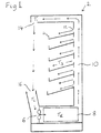
Figure 1 shows in cross-section a refrigerated
display cabinet 2, which is one example of such a
refrigeration system. The cabinet 2 has a number of
shelves for displaying chilled food or drinks. The
cabinet 2 is open at the front (to the left in Figure
1) to allow shoppers easy access to the contents of
the shelves 4. The contents are cooled by air blown
by a fan 6 over an evaporator 8 of the refrigeration
system, which cools the air. As shown by the arrows
in Figure 1, the air leaves the evaporator 8, is
forced up a duct 10 and escapes through small vents 12
so that some of the air flows over the contents of the
shelves 4.
Most of the air passes through an end aperture 14
at the top of the cabinet 2 and falls as a curtain of
cold air down the open front of the cabinet 2 and
into an inlet 16, to be recirculated over the
evaporator 8. The air curtain hinders the warm
ambient air from entering the cabinet.
However, some of the ambient air is drawn into
the inlet 16. The ambient air includes water vapour
which condenses and freezes on the evaporator 8 to
form frost. The frost impedes the passage of air over
the evaporator 8 and reduces the efficiency of heat
exchange between the evaporator 8 and the air. If the
frost is allowed to build up, the rate of airflow will
be reduced sufficiently to prevent the air curtain
from forming and the internal temperature of the
cabinet will rise. Furthermore, the efficiency of the
refrigeration system will be reduced, leading to
higher running costs.
For these reasons, it is necessary to defrost the
evaporator 8 in such refrigeration systems every few
hours. There are different conventional methods by
which this can be done. In the "air over" or "off
cycle" method, the refrigeration is stopped and the
evaporator 8 is defrosted by air at ambient
temperature passing over it. In the electric defrost
method, electric heating elements are provided around
the evaporator 8. During a defrost cycle, the flow of
refrigerant through the evaporator 8 is stopped and
the electric heating elements are switched on, thereby
melting the frost. The fan 6 may be switched off.
In the gas defrost method, gas is passed through
the evaporator so as to warm it and melt the frost.
The gas may be directed from the outlet of the
compressor of the refrigeration system through the
evaporator, so that the evaporator 8 acts temporarily
as a condenser and the refrigeration cycle acts in
reverse to release heat from the evaporator 8. This
is known as the "hot gas" method.
Alternatively, the gas may be taken from the top
of the receiver of the refrigeration system, in which
the refrigerant is stored before passing through the
expansion valve. This is known as the "cool gas"
method, since the refrigerant has passed through the
condenser and is cool.
During a defrost, the air temperature inside the
cabinet 2 rises above the normal storage temperature,
and the contents are subject to "temperature shock".
The effect of this temperature shock is to reduce the
shelf life of perishable goods. Moreover, the defrost
cycle consumes a significant amount of energy,
typically around 10% of the total energy used in
refrigeration.
Therefore defrost cycles should not occur too
frequently, but neither should they occur so
infrequently that the refrigeration efficiency of the
cabinet 2 is impaired.
In one conventional method of defrost control, a
defrost is initiated periodically at intervals
sufficiently short to prevent the evaporator 8 from
frosting up completely and thereby blocking the flow
of air, even at the maximum absolute humidity for
which the cabinet 2 is designed. This interval is
typically between 6 and 8 hours. However, when the
absolute humidity is less than its maximum, defrosts
occur more frequently than required.
It is therefore desirable to initiate a defrost
"on demand", that is to say only when it is needed.
Methods of initiating defrost on demand have been
proposed, in which the depth of ice on the evaporator
is detected by frost sensors. These add to the cost
of the refrigeration system.
The document EP-A-0 494 785 describes a defrost
control system using a temperature sensor within an
evaporator unit to determine when defrost is required.
The document US 5,319,943 describes a defrost
control system for a heat pump, using temperature
sensors which measure the temperature of the ambient
air and of an outdoor coil which is operable as an
evaporator.
The document US 5,493,867 describes a defrost
control system which uses "fuzzy logic" to vary the
interval between defrosts according to the time taken
to complete a defrost operation.
Such methods, while allowing the defrost interval
to vary according to the environment of the heat
transfer system, are not able directly to determine
when the efficiency of the evaporator has become
unacceptable and a defrost is therefore required.
According to one aspect of the present invention,
there is provided apparatus according to claim 1.
According to another aspect of the present invention,
there is provided a method according to claim 13.
An advantage of the invention is that the
superheat of refrigerant at the evaporator outlet is
used to determine when defrosting is required. The
superheat of the refrigerant provides a more direct
measurement of the efficiency of the evaporator than
the methods of the state of the art, since if the
superheat falls below a minimum level, this indicates
that insufficient heat is absorbed by the evaporator,
which may be a result of frost on the evaporator.
The superheat itself may be measured, or a liquid
sensor may be used to determine whether liquid
refrigerant is present at the outlet, indicating that
the refrigerant has no superheat. Use of a liquid
sensor is preferred, since the refrigerant leaving the
evaporator should have as low a superheat as possible,
for efficient use of the evaporator, but liquid should
be prevented from entering the compressor. The liquid
sensor is suitable for detecting a point at which both
criteria are satisfied.
Preferably an expansion valve through which
refrigerant flows into the evaporator is controlled
according to a sensed temperature of the thermal load
of the heat transfer system. The control is
overridden and the flow through the expansion valve is
reduced when the degree of superheat of refrigerant at
the evaporator outlet falls below a predetermined
level or a predetermined proportion of liquid is
detected at the outlet. Defrost of the evaporator is
initiated when the overrides exceed a predetermined
level.
Hence, defrost is initiated when the evaporator
is no longer able continuously to maintain the
temperature of the thermal load within a desired range
without causing the superheat of the refrigerant at
the outlet to fall below a minimum level or liquid to
appear at the outlet. This situation is a direct
result of the reduction in efficiency of the
evaporator due to frost. Hence, defrost is only
initiated when it is required to overcome this
reduction in efficiency.
Specific embodiments of the present invention
will now be described with reference to the
accompanying drawings in which:
A specific embodiment of the present invention
will now be described with reference to Figures 1 to
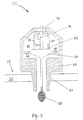
4. Figure 2 shows part of the refrigeration system,
comprising an expansion valve 18 through which
refrigerant at high pressure from the condenser is
admitted into the evaporator 8 at low pressure. The
expansion valve 18 is controlled by an electrical
signal on a line 20 connected to a control circuit 22.
The control circuit 22 controls the time periods for
which the expansion valve 18 is opened and closed
within a continuously repeated cycle. The cycle is
typically one of six or eight seconds duration, the
valve being pulsed open once in each cycle for a
period determined by the required flow rate. Other
types of electrically controlled valve may be used,
such as a stepper motor valve.
As the refrigerant passes at low pressure through
the evaporator 8, it evaporates and absorbs heat from
the air surrounding the evaporator 8 as the latent
heat of evaporation. The evaporated refrigerant
passes through an outlet 24 of the evaporator 8 and is
returned through a suction pipe to a compressor 26
which compresses the refrigerant to high pressure and
outputs it to the condenser (not shown), where the
refrigerant condenses and releases the latent heat.
A temperature sensor 28 senses the temperature
outside the evaporator 8. For example, as shown in
Figure 1, the temperature sensor 28 may be positioned
to sense the external temperature TE around the
evaporator 8, the "air off" temperature T1 of air
leaving the duct 10, the "air on" temperature T2 of air
entering the inlet 16 or the temperature T3 of the
storage area of the cabinet. The temperature sensor
28 generates an electrical signal representing the
sensed temperature on the line 30, which is input to
the control circuit 22.
In normal operation, the control circuit 22 sets
the duty ratio of the signal on the line 20 according
to the relationship between the temperature sensed by
the temperature sensor 28 and a desired temperature
range programmed in the control circuit 22. If the
sensed temperature is below the desired range, the
expansion valve 18 will be open for a shorter period,
so as to reduce the flow of refrigerant to the
evaporator 8, whereas when the sensed temperature is
above the desired range, the expansion valve 18 is
open for a longer period so as to increase the flow of
refrigerant through the evaporator 8.
However, if the flow of refrigerant through the
evaporator 8 is increased to such an extent that not
all of the liquid refrigerant evaporates in evaporator
8, liquid refrigerant will be present at the outlet 24
of the evaporator 8 and may subsequently enter and
damage the compressor 26.
In order to prevent liquid refrigerant from
entering the compressor 26, a superheat sensor 32 is
provided at the outlet 24 of the evaporator 8. The
superheat sensor detects the level of superheat of the
refrigerant, which is the temperature difference by
which the temperature of the refrigerant exceeds the
boiling point of the refrigerant at the outlet
pressure. If the superheat is zero, the refrigerant
is at boiling point and there will be liquid
refrigerant present at the outlet 24.
The superheat sensor 32 outputs an electrical
signal on a line 34 to the control circuit 22, whereby
the control circuit 22 detects whether the degree of
superheat has fallen below a predetermined safe level.
In that case, the control circuit 22 enters an
"override" condition in which it controls the
expansion valve 18 to reduce the flow of refrigerant
through the evaporator 8 until the detected degree of
superheat rises above a predetermined level, which may
be the same as or different from the minimum level.
Suitable sensors 32 for detecting superheat are
described in more detail in UK patent publication
number 2,302,725 which is incorporated herein by
reference. One example of such a device will now be
described with reference to Figure 3. The device
comprises a body 60 having a portion 61 which is
threaded so as to permit the device to be mounted in
a fluid-sealing manner in the wall 25' of the suction
pipe 25 at the outlet 24 of the evaporator 8. The
body 60 has an internal chamber 63 which is in open
communication with the fluid flowing through the pipe
25 at the end having the threaded portion 61. A
movable member in the form of a flexible diaphragm 62
is mounted within the chamber 63 on support elements
64 and 66.
The upperside of the diaphragm 62 in the drawing
is in open communication with the fluid within the
chamber 63, via respective apertures 65, 67 in the
support elements 64, 66. This upperside of the
diaphragm is thereby subject to the vapour pressure of
the fluid at the outlet 24 of the evaporator. The
lower side of the diaphragm is isolated from the
vapour pressure of the refrigerant fluid within the
chamber 63, and is coupled instead to a container in
the form of a phial 68 containing a quantity of
liquid, as indicated by the horizontal shading in the
drawing. The coupling forms a closed sub-chamber 69
containing a saturated vapour of the liquid within the
phial. In this embodiment, the phial is fixed in its
location with respect to the body of the sensor device
and is disposed substantially externally of the body.
Thus, the phial is surrounded by the refrigerant fluid
flow, its liquid content acquires the temperature of
that fluid, and a vapour pressure corresponding to
that temperature is exerted on the lower side of the
diaphragm by the vapour within the sub-chamber 69.
A difference in the respective vapour pressures
exerted on the opposite, upper and lower surfaces of
the diaphragm 62 determines a vertical displacement of
the diaphragm which is related to the amount of
superheat. A detector for the diaphragm displacement
is housed in the support element 66. The detector
comprises an elongate linearly-movable member 70
coupled to the diaphragm, and a position sensor 71 for
sensing the position of the member 70. The position
sensor 71 thus outputs an electrical signal related to
the sensed superheat, the signal being led out at the
top end of the body 60 through a Fusite™ connector 72
which provides the necessary pressure seal. The
output signal is supplied to the control circuit 22 on
line 34.
The liquid in the phial 68 preferably has a
composition which is the same as, or very similar to,
that of the refrigerant circulated through the
evaporator. If the refrigerant is a mixture of
substances having different boiling points, the liquid
in the phial 68 should substantially match the least
volatile component of the mixture, since that
component will determine whether there is any
superheat in the refrigerant. In both these cases,
the vapour pressure exerted on the longer side of the
diaphragm 62 will be that required for measuring the
superheat. Alternatively, a known substance,
different from the refrigerant, may be used for the
phial liquid. In that case, a correction needs to be
made to the electrical signal output by the position
sensor 71. The correction is to allow for the
relationship between the different vapour pressure-temperature
characteristics of the liquid in the phial
(which determines the vapour pressure in the sub-chamber
69) and the refrigerant in the evaporator
(which determines the vapour pressure in the chamber
63).
Alternatively, the superheat sensor 32 may
comprise a device for detecting the presence of liquid
in the flow of refrigerant at the outlet 24. Such
devices are described in UK patent publication numbers
2,302,725 and 2,308,192. The latter is also
incorporated herein by reference. One example of such
a device will now be described with reference to
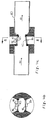
Figures 4a and 4b.
The device comprises principally a tube 80 and a
number of components 84 to 86 mounted on the tube,
externally thereof. The components consist of a first
temperature sensor 85, an electrical heating element
86 mounted adjacent the sensor 85, and a second
temperature sensor 84. In this embodiment the two
temperature sensors 84, 85 are each temperature-dependent
resistors or thermistors, whereas the
heating element 86 is an electrical resistor. The
thermistor 85 and heating resistor 86 are mounted
side-by-side on a first portion or member 83 of the
tube wall. The other thermistor 84 is mounted on a
second portion or member 82 of the tube wall,
diametrically opposing the first portion. The tube 80
is made of a material having a good thermal
conductivity, preferably a metal or metal alloy. In
this embodiment a copper tube is used.
In operation, a fluid which is normally in the
gas state flows through the tube 80 in a direction
indicated generally by the arrows 81 in Figure 4a.
Both of the thermistors 84, 85 are responsive to the
temperature of the fluid flowing past the members 82,
83. In a wholly gaseous fluid, the member 82 will
acquire substantially the gas temperature and this
temperature is sensed by the thermistor 84. On the
other hand, the member 83 will acquire a temperature
higher than the gas temperature due to the heating
effect of the resistor 86, and this higher temperature
is sensed by the thermistor 85.
Thus, when the fluid is completely gaseous and
contains no liquid component, there will exist a
definite temperature difference between the
temperatures sensed by the sensors 84, 85, the
difference being determined practically by the
magnitude of the current supplied to the heating
resistor 86. The difference between the two sensed
temperatures is of the order of a few degrees Celsius.
In this embodiment, the temperature difference is
monitored by a detection means comprising a comparator
(not shown). The comparator may be incorporated in
the apparatus itself, but it is conveniently provided
in the control circuit 22. The detection means is
readily implemented using electronic components with
which the skilled person is familiar. The outputs of
the temperature sensors 84 and 85 may be connected by
the line 34 to the control circuit 22.
When liquid appears in the fluid flowing through
the tube, the liquid comes into contact with the
heated wall portion 83 of a temperature exceeding that
of the fluid. The effect of this contact is that the
liquid immediately vaporises, the heated portion 83
providing the necessary latent heat for the change of
state. The vaporisation of the liquid is manifest by
a rapid or sudden lowering of the temperature of the
portion 83, which is detected by the thermistor 85.
Thus, by monitoring the difference between the
temperatures sensed by the thermistors 84 and 85, the
occurrence of liquid in the fluid flow can be quickly
and reliably established by detecting the
corresponding lowering of the temperature difference.
For example, the detection may be achieved by setting
a threshold for the output of the comparator: if the
output level, corresponding to the temperature
difference, falls below the threshold (for example,
instantaneously or for a predetermined period), an
output signal indicating liquid detection is
generated.
The size of the temperature difference is
dependent on the amount of liquid, i.e. the ratio of
liquid to gas in the fluid being monitored. Thus, it
is possible to set the threshold for detection at a
level which corresponds to a particular degree of
wetness which needs to be checked.
The two portions 82, 83 of the tube wall on which
the sensing components 84 to 86 are mounted, are
substantially thermally isolated from each other.
In Figure 2, a defrost heater 36 is arranged
around the evaporator 8 and can be electrically heated
so as to defrost the evaporator 8. The defrost heater
36 is switched on and off under the control of an
electrical signal on line 38 from the control circuit
22.
When the control circuit 22 determines that the
evaporator 8 should be defrosted, it switches on the
defrost heater 36 and closes the expansion valve 18
for the duration of the defrost cycle.
In this example, the electric defrost method is
used. Alternatively the air or gas methods, or other
known methods of defrosting an evaporator may be used
under the control of the control circuit 22.
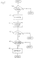
The algorithm executed by the control circuit 22
to initiate defrosting will now be described with
reference to the flow chart of Figure 5. At step 40,
the control circuit 22 determines, by means of the
superheat sensor 32, whether the refrigerant at the
outlet 24 has less than the predetermined minimum
level of superheat. If so, the control circuit 22
reduces the open period of the expansion valve 18 by
an amount dependent on the level of superheat below
the minimum level or the degree of wetness, at step
42.
At step 44 the control circuit 22 records the
period of time for which the detected superheat was
below the minimum level and stores this value in an
internal memory, together with the time at which it
occurred. At step 46, the control circuit 22
determines whether the superheat was below the minimum
level for more than a percentage x% of the last y
minutes. Preferably, x is between 25 and 40%, and y
is 30 minutes.
Alternatively, the control circuit 22 may simply
record the number of times the superheat fell below
the minimum level in the last y minutes, although this
method is less preferred since it is less sensitive.
At step 48, the control circuit 22 determines
whether more than z hours have elapsed since the last
defrost, where z is preferably 6 hours. If so, at
step 50, the control circuit 22 initiates defrosting
of the evaporator 8. If less than z hours have
elapsed since the last defrost, the control circuit 22
ends the algorithm without initiating a defrost.
In one alternative, defrost is automatically
initiated if more than a maximum period, such as 2
days, has elapsed since the last defrost, since there
is little incremental gain in defrosting at intervals
greater than this maximum period.
In one example, in which the refrigerated display
cabinet 2 is a stand-alone cabinet, the control
circuit 22 begins the defrost cycle immediately.
Alternatively, the defrost cabinet 2 may be one
of an array of refrigerated cabinets, such as is used
in a supermarket. In that case, there is a maximum
number of display cabinets which can be defrosted at
any one time, in order to limit the load on the
defrosting system. The defrosting of cabinets is
therefore coordinated to avoid exceeding this maximum
number.
If a gas defrost method is used, the hot or cool
gas may be distributed from a central plant room to
the evaporators of the cabinets to be defrosted. The
control circuit 22 is connected through a
communications network to a defrost controller located
in the plant room. The defrost controller controls
the opening and closing of valves to direct the hot or
cool gas to the evaporators selected for defrosting.
At step 50 the control circuit 22 sends a signal
to the remote defrost controller, which adds data
representing the refrigerated cabinet 2 to a defrost
queue. The remote defrost controller defrosts the
cabinets in the order of the queue.
In such a system, a delay is incurred between
entering the cabinet on the defrost queue, at step 50,
and defrosting of the evaporator 8. However, the
frequency of "overrides", at which the superheat falls
below the minimum level or to zero, begins to increase
a considerable time before the defrost becomes
essential. Therefore, the values of x and y can be
set so that, even allowing for the queuing delay,
defrosting takes place before the evaporator 8 frosts
up completely.
Alternatively, the hot or cool gas can be
supplied through a ring main, separately from the
normal supply of refrigerant. When the control
circuit 22 initiates defrost, it opens a valve to
connect the evaporator 8 to the ring main. The
control circuit 22 of each display cabinet may be
connected to a communications network so as to
coordinate defrosting to avoid exceeding the maximum
number of cabinets which are defrosted at any one
time. In this case, the control circuit may initiate
defrosting by sending a defrost request signal over
the network and open the valve in response to a
defrost control signal from the network.
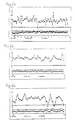
A practical example of the operation of the
defrost algorithm shown in Figure 3 will now be
described with reference to the graphs shown in
Figures 6a to 6i and Table 1 below.
In this example, the evaporator 8 was last
defrosted at 15.00 hours on Tuesday. The graphs show
the degree of superheat, the cabinet temperature T3 and
the evaporator temperature TE as a function of time.
The minimum superheat level is set at 6°C and the
desired cabinet temperature T3 at 1°C.
Table 1 below records the time at which overrides
occur, the approximate length in minutes of these
overrides, and the total period of overrides in the
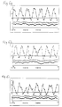
last thirty minutes. Graph 6a covers the period from
18.00 hours on Tuesday to 11.00 on Wednesday, while
graphs 6b to 6i each cover one hour of a sequence from
09.00 hours to 18.00 hours on Wednesday, excluding
from 13.00 to 14.00 hours, for which no data was
available. The last two hours of graph 6a are covered
by graphs 6b and 6c.
Until approximately 10.45 on Wednesday, only
occasional overrides occur. Some of these overrides
are of sufficiently short duration that they are not
recorded on the graphs.
At 12.45, the control circuit 22 has been in the
override state for 9 minutes, which is greater than
25%, of the last 30 minutes. More than 6 hours have
elapsed since the last defrost, at 15.00 hours on
Tuesday. Therefore, the control circuit 22 reaches
step 50 and triggers a defrost by entering the
evaporator 8 on the defrost queue. After the defrost
has been triggered at step 50, but before defrosting
occurs, overrides occur at more or less regular
intervals but the cabinet temperature T3 does not vary
significantly from the ideal temperature of 1°C.
At 18.30, after the time period shown in graph
6i, the evaporator 8 is defrosted. To reduce the
temperature shock and energy consumption caused by a
defrost cycle, the defrost cycle should stop as soon
as possible after all the ice on the evaporator 8 has
melted. The temperature TE in the vicinity of the
evaporator 8 is measured and the defrost cycle is
stopped when the temperature rises above a
predetermined level, such as 15°C. If the temperature
has not risen above this level after a predetermined
period, then the defrost cycle is stopped.
Alternatively, the evaporator 8 may be isolated
from the rest of the system and the pressure within
the evaporator is measured. Provided the evaporator
contains a mixture of liquid and gaseous refrigerant,
the vapour pressure inside the evaporator 8 is used to
determine the temperature of the evaporator. When
this temperature has risen above a predetermined
level, the defrost cycle is stopped. Alternatively,
the defrost period is determined by a timer set so as
to ensure that all the frost has melted, without
causing too great a temperature shock.
Since the defrost cycle is only activated for a
short time, the temperature of the cabinet contents
does not rise sufficiently to cause spoiling of
perishable goods.
Although the above embodiment has been described
with reference to a refrigerated display cabinet, it
will be appreciated that the present invention is also
applicable to any heat transfer system in which
frequent defrosting of an evaporator 8 is required.
For example, the present invention is also applicable
to freezer display cabinets, blast chillers, blast
freezers, air conditioners or heat pumps in which heat
is extracted from ambient air or water in a heating
system.
In the embodiments described above, two different
methods are described for detecting whether the
superheat of refrigerant leaving the evaporator is at
or below a predetermined level. Other methods may be
used without departing from the scope of the
invention. For example, the outlet pressure and
temperature may be detected and may be used to
calculate the degree of superheat, or a lookup table
may be used to determine which values of pressure and
temperature correspond to a degree of superheat below
the predetermined level. Other methods of detecting
the presence of liquid in the refrigerant may be used,
such as described in the document GB-A-2 157 447, for
example.