EP0816692B1 - Fixing element for dynamic forces - Google Patents
Fixing element for dynamic forces Download PDFInfo
- Publication number
- EP0816692B1 EP0816692B1 EP97109432A EP97109432A EP0816692B1 EP 0816692 B1 EP0816692 B1 EP 0816692B1 EP 97109432 A EP97109432 A EP 97109432A EP 97109432 A EP97109432 A EP 97109432A EP 0816692 B1 EP0816692 B1 EP 0816692B1
- Authority
- EP
- European Patent Office
- Prior art keywords
- bolt
- fastening element
- energy storage
- element according
- storage means
- Prior art date
- Legal status (The legal status is an assumption and is not a legal conclusion. Google has not performed a legal analysis and makes no representation as to the accuracy of the status listed.)
- Expired - Lifetime
Links
- 238000004873 anchoring Methods 0.000 claims abstract description 9
- 229910000831 Steel Inorganic materials 0.000 claims abstract description 8
- 229920001971 elastomer Polymers 0.000 claims abstract description 8
- 239000010959 steel Substances 0.000 claims abstract description 8
- 239000011248 coating agent Substances 0.000 claims abstract description 6
- 239000000806 elastomer Substances 0.000 claims abstract description 6
- 229910052782 aluminium Inorganic materials 0.000 claims abstract description 3
- XAGFODPZIPBFFR-UHFFFAOYSA-N aluminium Chemical compound [Al] XAGFODPZIPBFFR-UHFFFAOYSA-N 0.000 claims abstract description 3
- 239000006260 foam Substances 0.000 claims abstract description 3
- 239000004411 aluminium Substances 0.000 claims abstract 2
- 238000004146 energy storage Methods 0.000 claims description 20
- 239000004570 mortar (masonry) Substances 0.000 claims description 7
- 239000006262 metallic foam Substances 0.000 claims description 3
- 239000001993 wax Substances 0.000 claims description 2
- 239000004925 Acrylic resin Substances 0.000 claims 1
- 239000004922 lacquer Substances 0.000 claims 1
- 239000000203 mixture Substances 0.000 claims 1
- KCTAWXVAICEBSD-UHFFFAOYSA-N prop-2-enoyloxy prop-2-eneperoxoate Chemical compound C=CC(=O)OOOC(=O)C=C KCTAWXVAICEBSD-UHFFFAOYSA-N 0.000 claims 1
- 238000000576 coating method Methods 0.000 abstract description 5
- 239000002966 varnish Substances 0.000 abstract description 5
- JIGUICYYOYEXFS-UHFFFAOYSA-N 3-tert-butylbenzene-1,2-diol Chemical compound CC(C)(C)C1=CC=CC(O)=C1O JIGUICYYOYEXFS-UHFFFAOYSA-N 0.000 abstract description 2
- 239000005011 phenolic resin Substances 0.000 abstract description 2
- 229920005989 resin Polymers 0.000 abstract description 2
- 239000011347 resin Substances 0.000 abstract description 2
- 229910052751 metal Inorganic materials 0.000 description 4
- 239000002184 metal Substances 0.000 description 4
- 230000000284 resting effect Effects 0.000 description 4
- 150000001875 compounds Chemical class 0.000 description 3
- -1 polysiloxane Polymers 0.000 description 3
- 239000007787 solid Substances 0.000 description 3
- 239000003795 chemical substances by application Substances 0.000 description 2
- 239000002131 composite material Substances 0.000 description 2
- 238000010586 diagram Methods 0.000 description 2
- 238000003780 insertion Methods 0.000 description 2
- 230000037431 insertion Effects 0.000 description 2
- 230000036316 preload Effects 0.000 description 2
- KXGFMDJXCMQABM-UHFFFAOYSA-N 2-methoxy-6-methylphenol Chemical compound [CH]OC1=CC=CC([CH])=C1O KXGFMDJXCMQABM-UHFFFAOYSA-N 0.000 description 1
- OKTJSMMVPCPJKN-UHFFFAOYSA-N Carbon Chemical compound [C] OKTJSMMVPCPJKN-UHFFFAOYSA-N 0.000 description 1
- 239000004743 Polypropylene Substances 0.000 description 1
- 239000005083 Zinc sulfide Substances 0.000 description 1
- 238000010521 absorption reaction Methods 0.000 description 1
- 230000005540 biological transmission Effects 0.000 description 1
- 239000011449 brick Substances 0.000 description 1
- 239000004566 building material Substances 0.000 description 1
- 239000011455 calcium-silicate brick Substances 0.000 description 1
- 239000004567 concrete Substances 0.000 description 1
- 230000007797 corrosion Effects 0.000 description 1
- 238000005260 corrosion Methods 0.000 description 1
- 229910002804 graphite Inorganic materials 0.000 description 1
- 239000010439 graphite Substances 0.000 description 1
- 239000000314 lubricant Substances 0.000 description 1
- 238000012423 maintenance Methods 0.000 description 1
- 239000000463 material Substances 0.000 description 1
- 150000002739 metals Chemical class 0.000 description 1
- CWQXQMHSOZUFJS-UHFFFAOYSA-N molybdenum disulfide Chemical compound S=[Mo]=S CWQXQMHSOZUFJS-UHFFFAOYSA-N 0.000 description 1
- 239000003973 paint Substances 0.000 description 1
- 229920001568 phenolic resin Polymers 0.000 description 1
- 239000002985 plastic film Substances 0.000 description 1
- 229920006255 plastic film Polymers 0.000 description 1
- 229920000098 polyolefin Polymers 0.000 description 1
- 229920001155 polypropylene Polymers 0.000 description 1
- 229920001296 polysiloxane Polymers 0.000 description 1
- 229920001343 polytetrafluoroethylene Polymers 0.000 description 1
- 239000004810 polytetrafluoroethylene Substances 0.000 description 1
- 230000035939 shock Effects 0.000 description 1
- 239000000344 soap Substances 0.000 description 1
- 229910052984 zinc sulfide Inorganic materials 0.000 description 1
- DRDVZXDWVBGGMH-UHFFFAOYSA-N zinc;sulfide Chemical compound [S-2].[Zn+2] DRDVZXDWVBGGMH-UHFFFAOYSA-N 0.000 description 1
Images


Classifications
-
- F—MECHANICAL ENGINEERING; LIGHTING; HEATING; WEAPONS; BLASTING
- F16—ENGINEERING ELEMENTS AND UNITS; GENERAL MEASURES FOR PRODUCING AND MAINTAINING EFFECTIVE FUNCTIONING OF MACHINES OR INSTALLATIONS; THERMAL INSULATION IN GENERAL
- F16B—DEVICES FOR FASTENING OR SECURING CONSTRUCTIONAL ELEMENTS OR MACHINE PARTS TOGETHER, e.g. NAILS, BOLTS, CIRCLIPS, CLAMPS, CLIPS OR WEDGES; JOINTS OR JOINTING
- F16B13/00—Dowels or other devices fastened in walls or the like by inserting them in holes made therein for that purpose
- F16B13/14—Non-metallic plugs or sleeves; Use of liquid, loose solid or kneadable material therefor
- F16B13/141—Fixing plugs in holes by the use of settable material
-
- F—MECHANICAL ENGINEERING; LIGHTING; HEATING; WEAPONS; BLASTING
- F16—ENGINEERING ELEMENTS AND UNITS; GENERAL MEASURES FOR PRODUCING AND MAINTAINING EFFECTIVE FUNCTIONING OF MACHINES OR INSTALLATIONS; THERMAL INSULATION IN GENERAL
- F16B—DEVICES FOR FASTENING OR SECURING CONSTRUCTIONAL ELEMENTS OR MACHINE PARTS TOGETHER, e.g. NAILS, BOLTS, CIRCLIPS, CLAMPS, CLIPS OR WEDGES; JOINTS OR JOINTING
- F16B31/00—Screwed connections specially modified in view of tensile load; Break-bolts
- F16B31/04—Screwed connections specially modified in view of tensile load; Break-bolts for maintaining a tensile load
- F16B31/043—Prestressed connections tensioned by means of liquid, grease, rubber, explosive charge, or the like
Definitions
- Fasteners are used for non-resting, dynamic loads, for example needed to fasten machines, conveyor systems or other components, to absorb the high, dynamic, sometimes shock-like loads.
- the Known, provided for this application fasteners are mostly after biased axially in the mounting base to the strong dynamic forces that act on the fastening in the fastening underground derive.
- Practice shows that the preload applied by the occurring dynamic loads are greatly reduced in a short time.
- a dowel or fastening element of the aforementioned is in DE-OS 3 331 097 Kind of suggested the with one between the counter bearing on the bolt and the one to be fastened Provided object energy storage in the form of a spring element is.
- the invention is based on the object to create a fastener for dynamically resilient fastenings that constant maintenance of tension and space-saving fastening allows.
- foamed materials for example aluminum foam
- the modulus of elasticity of foamed metals over the density in another area can be varied, there is the possibility of energy absorption of the energy store to influence so that the elasticity of the fastener to the expected rapid loading can be set.
- the fastening element is inserted into the borehole for anchoring.
- the longitudinal gap between the bolt and the borehole wall with a hardening mortar filled. After the mortar has hardened, a solid one is created in the borehole anchored mortar core, which surrounds the bolt and as a support for the energy storage acts.
- Coatings for example in the form of a Paint can be used.
- a varnish as a coating can this radically curing reactive resin system, e.g. t-butyl catechol or Phenolic resin varnish may be buried.
- a metal one Coating e.g. B. apply a galvanic coating.
- the bolt can with a release agent such as plastic film or the like, which has certain sliding properties has and based on polysiloxane, polyolefin, polytetrafluoroethylene, Polypropylene and the like is provided.
- Lubricants such as are also possible Graphite, zinc sulfide, molybdenum sulfide, metal soaps and waxes.
- FIG. 4 shows, similar to FIG. 1, a fastening element according to the invention after insertion into the borehole, the energy store 3a being made of a metallic foam.
- the energy store 3a is arranged between two steel disks 4. After the fastening element has been pretensioned, the energy store 3a is compressed. Energy store 3a will press against the borehole wall, as shown in FIG. 5.
- a further modified form of the energy store 3, which is shown in FIG. 6, consists of a plate spring 19 which is embedded in an energy store 3 made of an elastomer and arranged between two steel disks. After prestressing the fastening element, the spring deforms in the axial direction, as shown in FIG. 7.
Abstract
Description
Die Erfindung betrifft ein Befestigungselement für nichtruhende Belastungen zum Befestigen von Maschinen, Fördereinrichtungen oder sonstigen Bauteilen gemäß der Gattung des Anspruches 1.The invention relates to a fastening element for non-resting loads for fastening of machines, conveyors or other components according to the genus of claim 1.
Befestigungselemente werden für nichtruhende, dynamische Lasten beispielsweise zum Befestigen von Maschinen, Födereinrichtungen oder sonstigen Bauteilen benötigt, um die hohen, dynamischen manchmal auch schockartigen Lasten aufzunehmen. Die bekannten, für diese Anwendung vorgesehenen Befestigungselemente sind meist nach dem Setzen im Befestigunguntergrund in axialer Richtung vorgespannt, um die starken dynamischen Kräfte, die auf die Befestigung einwirken, in den Befestigungsuntergrund abzuleiten. Die Praxis zeigt, daß die aufgebrachte Vorspannung durch die auftretenden dynamischen Belastungen in kurzer Zeit stark reduziert wird. Um diesen Abbau der Vorspannkraft zu unterbinden, ist in der DE-OS 3 331 097 ein Dübel bzw. Befestigungselement der eingangs genannten Art vorgeschlagen, der mit einem zwischen dem Gegenlager am Bolzen und dem zu befestigenden Gegenstand angeordneten Energiespeicher in Form eines Federelementes versehen ist. Fasteners are used for non-resting, dynamic loads, for example needed to fasten machines, conveyor systems or other components, to absorb the high, dynamic, sometimes shock-like loads. The Known, provided for this application fasteners are mostly after biased axially in the mounting base to the strong dynamic forces that act on the fastening in the fastening underground derive. Practice shows that the preload applied by the occurring dynamic loads are greatly reduced in a short time. To reduce this preload to prevent, a dowel or fastening element of the aforementioned is in DE-OS 3 331 097 Kind of suggested the with one between the counter bearing on the bolt and the one to be fastened Provided object energy storage in the form of a spring element is.
Das Federelement weist eine von der zulässigen Gebrauchslast abhängige Spannkraft auf und ist außerhalb des Bohrlochs angeordnet. Als nachteilig hat sich gezeigt, daß bei hohen Lastwechselzahlen große Flächenpressungen zwischen den einzelnen Federn auftreten, die zur Beschädigung der Federfläche durch Reibkorrosion führen. Als Folge dessen tritt eine rapide Reduzierung der Vorspannkraft auf, die einen Schlupf des Dübels verursacht und zum Versagen der Befestigung führen kann. Ferner nimmt auch die Elastizität des Energiespeichers ab, so daß die Fähigkeit zur Aufnahme dynamischer Lasten verloren geht.The spring element has a clamping force that depends on the permissible working load and is located outside of the borehole. It has been shown to be disadvantageous that at high load changes, large surface pressures between the individual Springs occur that damage the spring surface due to fretting corrosion. As a result, there is a rapid reduction in the biasing force, which causes slippage caused by the anchor and can lead to failure of the attachment. Further takes also the elasticity of the energy storage, so that the ability to absorb dynamic loads are lost.
Des weiteren ist die Anordnung des Federelementes auf der Außenfläche des zu befestigenden Gegenstandes aus Platzgründen nicht in allen Fällen möglich.Furthermore, the arrangement of the spring element on the outer surface of the to be fastened Object not possible in all cases due to lack of space.
Ausgehend vom diesem Stand der Technik liegt der Erfindung die Aufgabe zugrunde, ein Befestigungselement für dynamisch belastbare Befestigungen zu schaffen, das eine konstante Erhaltung der Spannkraft sowie eine platzsparende Befestigung ermöglicht.Starting from this prior art, the invention is based on the object to create a fastener for dynamically resilient fastenings that constant maintenance of tension and space-saving fastening allows.
Die Lösung dieser Aufgabe wird durch die im Kennzeichnungsteil des Anspruchs 1 angegebenen Merkmale erreicht.This object is achieved by the features specified in the characterizing part of claim 1.
Der am vorderen im Bohrloch befindlichen Ende des Bolzen angeordnete Energiespeicher stützt sich an der den Verankerungsbereich bildenden ausgehärteten Verbundmasse ab, so daß die über den Bolzen geleitenden dynamischen Belastungen über den Energiespeicher abgefangen werden. Die axiale Bewegungsmöglichkeit des Bolzen innerhalb des Verankerungsbereichs wird durch verbundshindernde Mittel erreicht, mit denen der Bolzen versehen ist. Über einen am vorderen Ende des Bolzens angeordneten, bzw. durch eine Mutter gebildeten Anschlag wird die Schwingungsenergie des Bolzens in den Energiespeicher übertragen. Durch die Energieübertragung preßt sich der beispielsweise zwischen zwei Stahlscheiben eingeschlossene Energiespeicher, der aus einem Elastomer oder Metallschaum bestehen kann, an die Bohrlochwandung an und sichert, daß die Spannkraft des Befestigungselements konstant aufrechterhalten bleibt. Durch die Anbringung des Energiespeichers am vorderen, im Bohrloch befindlichen Ende des Bolzens wird zur Befestigung eines Gegenstandes nur der auf die Klemmdicke des Befestigungsgegenstandes abgestimmte Überstand des Bolzens benötigt. Damit ist mit dem erfindungsgemäßen Befestigungselement eine platzsparende, dynamische Lasten aufnehmende Befestigung möglich.The energy store arranged at the front end of the bolt located in the borehole is based on the hardened composite mass forming the anchoring area from, so that the dynamic loads passing over the bolt be intercepted via the energy storage. The axial possibility of movement of the Bolts within the anchoring area are prevented by means of compounds reached with which the bolt is provided. About one at the front end of the bolt arranged, or formed by a nut stop Vibration energy of the bolt is transferred to the energy store. Through the Energy transfer is pressed between two steel disks, for example enclosed energy storage device made of an elastomer or metal foam can exist on the borehole wall and ensures that the clamping force of the Fastener is maintained constant. By attaching the Energy storage at the front end of the bolt located in the borehole becomes Attachment of an object only to the clamping thickness of the Fixing object coordinated protrusion of the bolt required. With that is the fastener according to the invention a space-saving, dynamic loads receiving attachment possible.
Es hat sich gezeigt, daß der Einsatz von geschäumten Materialien, beispielsweise Aluminiumschaum, besonders geeignet ist, um Schockenergie zu vernichten. Da das Elastizitätsmodul von geschäumten Metallen über die Dichte in einem weiteren Bereich variiert werden kann, ergibt sich die Möglichkeit die Energieabsorbierung des Energiespeichers so zu beeinflussen, daß die Elastizität des Befestigungselements auf die zu erwartende Schnellbelastung eingestellt werden kann.It has been shown that the use of foamed materials, for example aluminum foam, is particularly suitable to destroy shock energy. Because the modulus of elasticity of foamed metals over the density in another area can be varied, there is the possibility of energy absorption of the energy store to influence so that the elasticity of the fastener to the expected rapid loading can be set.
Zum Verankern wird das Befestigungselement ins Bohrloch eingeführt. Der Längsspalt zwischen dem Bolzen und der Bohrlochwandung wird mit einer aushärtenden Mörtelmasse gefüllt. Nach dem Aushärten der Mörtelmasse entsteht ein fester, im Bohrloch verankerter Mörtelkern, der den Bolzen umschließt und als Abstützung für den Energiespeicher wirkt.The fastening element is inserted into the borehole for anchoring. The longitudinal gap between the bolt and the borehole wall with a hardening mortar filled. After the mortar has hardened, a solid one is created in the borehole anchored mortar core, which surrounds the bolt and as a support for the energy storage acts.
Als verbundhindernde Mittel können Beschichtungen, beispielsweise in Form eines Lackes eingesetzt werden. Bei der Verwendung eines Lackes als Beschichtung kann diesem radikalisch aushärtenden Reaktionsharzsystem, z.B. t-Butylcatechol oder Phenolharzlack beigesetzt sein. Es ist auch möglich, eine aus einem Metall bestehende Beschichtung, z. B. eine galvanische Beschichtung aufzubringen. Der Bolzen kann mit einem Trennmittel wie Kunststoffolie oder ähnlichem, das gewisse Gleiteigenschaften aufweist und auf der Basis von Polysiloxan, Polyolefin, Polytetrafluoräthylen, Polypropylen und ähnlichem besteht, versehen sein. Möglich sind auch Gleitmittel wie Graphit, Zinksulfid, Molybdänsulfid, Metallseifen und Wachse.Coatings, for example in the form of a Paint can be used. When using a varnish as a coating can this radically curing reactive resin system, e.g. t-butyl catechol or Phenolic resin varnish may be buried. It is also possible to use a metal one Coating, e.g. B. apply a galvanic coating. The bolt can with a release agent such as plastic film or the like, which has certain sliding properties has and based on polysiloxane, polyolefin, polytetrafluoroethylene, Polypropylene and the like is provided. Lubricants such as are also possible Graphite, zinc sulfide, molybdenum sulfide, metal soaps and waxes.
Die Verbindung zwischen dem Bolzen und dem Energiespeicher kann variabel gestaltet sein, beispielsweise kann der Energiespeicher auf dem Bolzen aufgeschraubt, oder der Bolzen mit den geschäumten Metallen umspritzt sein. Der Energiespeicher kann auch mit dem Bolzen verklebt oder durch eine Unterlegscheibe und Mutter festgehalten sein. The connection between the bolt and the energy store can be made variable be, for example, the energy storage screwed onto the bolt, or the The foamed metal is molded around the bolt. The energy storage can also glued to the bolt or held by a washer and nut.
Die Erfindung wird nachfolgend anhand der Zeichnungen näher erläutert.The invention is explained in more detail below with reference to the drawings.
Es zeigen:
- Figur 1
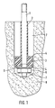
- das erfindungsgemäße Befestigungselement nach dem Enführen ins Bohrloch
Figur 2- das in Figur 1 dargestellte Befestigungselement während der Befüllung des Längsspaltes
Figur 3- das Befestigungslement nach Figur 1, vorgespannt
Figur 4- das in Figur 1 dargestellte Befestigungselement mit einem abgewandelten Energiespeicher
Figur 5- das in
Figur 4 dargestellte Befestigungselement, vorgespannt Figur 6- das in Figur 1 dargestellte Befestigungselement mit einem weiteren abgewandelten Energiespeicher
Figur 7- das in
Figur 6 dargestellte Befestigungselement, vorgespannt.
- Figure 1
- the fastener according to the invention after insertion into the borehole
- Figure 2
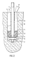
- the fastener shown in Figure 1 during the filling of the longitudinal gap
- Figure 3
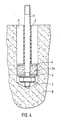
- the fastener of Figure 1, biased
- Figure 4
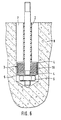
- the fastener shown in Figure 1 with a modified energy storage
- Figure 5
- the fastener shown in Figure 4, biased
- Figure 6
- the fastener shown in Figure 1 with a further modified energy storage
- Figure 7
- the fastener shown in Figure 6, biased.
Das in Figur 1 dargestellte Befestigungselement besteht aus einem Bolzen 1 und einem
Energiespeicher 3, der am vorderen im Bohrloch 7 befindlichen Ende des Bolzens 1 so
angeordnet ist, daß er sich an der den Verankerungsbereich bildenden, ausgehärteten
Verbundmasse abstützt. Die Außenfläche des Bolzens 1 ist mit einem
verbundhindernden Mittel 2 versehen. Der Ringspalt zwischen dem Bolzen 1 und der
Bohrlochwandung ist mit einer aushärtbaren Mörtelmasse befüllt. Der Energiespeicher
3 besteht aus einem Elastomer der zwischen zwei Stahlscheiben 4 angeordnet ist.
Ferner ist am vorderen Ende des Bolzens 1 eine Mutter 5 angebracht, die als Anschlag
dient und die Übertragung der Schwingungsenergie des Bolzens 1 in den
Energiespeicher 3 ermöglicht. Die Befüllung des Ringspaltes erfolgt über eine Kanüle
11, wie die Figur 2 zeigt. Nach dem Aushärten der Mörtelmasse entsteht ein fester
ringförmiger Mörtelkern 13, der den Bolzen 1, wie die Figur 3 zeigt, umschließt. The fastener shown in Figure 1 consists of a bolt 1 and a
Der in Figur 3 dargestellte Befestigungsgrund 8 ist vorzugsweise ein homogener fester
Baustoff wie Vollziegel, Kalksandstein oder Beton.The mounting
Das am Befestigungsgrund 8 zu befestigende Bauteil 12 wird mit Hilfe einer Muttter 5a
und der Unterlegscheibe 17 gegen die in Figur 3 dargestellte Oberkante 18 des
Befestigungselementes angedrückt.
Die Figur 4 zeigt, ähnlich wie die Figur 1, ein erfindungsgemäßes Befestigungselement
nach dem Einführen ins Bohrloch, wobei der Energiespeicher 3a aus einem
metallischen Schaum besteht. Der Energiespeicher 3a ist zwischen zwei Stahlscheiben
4 angeordnet. Nach der Vorspannung des Befestigungselementes erfolgt ein
Verdichten des Energiespeichers 3a. Dabei wird sich der Energiespeicher 3a an die
Bohrlochwandung anpressen, wie die Figur 5 zeigt.
Eine weitere abgewandelte Form des Energiespeichers 3, die in der Figur 6 dargestellt
ist, besteht aus einer Tellerfeder 19, die in einem zwischen zwei Stahlscheiben
angeordneten Energiespeicher 3 aus einem Elastomer eingelassen ist. Nach dem
Vorspannen des Befestigungselementes verformt sich die Feder in axiale Richtung, wie
die Figur 7 darstellt.The
FIG. 4 shows, similar to FIG. 1, a fastening element according to the invention after insertion into the borehole, the energy store 3a being made of a metallic foam. The energy store 3a is arranged between two
A further modified form of the
Ein praktisches Beispiel für die nichtruhenden Belastungen, die sich auf das erfindungsgemäße Befestigungselement nach Figur 1, 3 auswirkt, ist im Diagramm 1 dargestellt.A practical example of the non-resting burdens that affect the Fastening element according to the invention according to FIG. 1, 3, is shown in diagram 1 shown.
Ein weiteres Beispiel für die nichtruhenden Belastungen , die sich auf das Befestigungselement nach Figur 4,5 auswirkt, ist im Diagramm 2 dargestellt.Another example of the non-resting loads that affect the fastener according to Figure 4.5, is shown in diagram 2.
Claims (9)
- Fastening element for non-stationary loads, for the purpose of fastening machines, conveying devices or other building components, having a bolt (1) that is anchored in the drilled hole (7) by means of a hardenable mortar composition (12) that forms the anchoring region, on which bolt there is arranged an energy storage means (3), characterized in that the energy storage means (3) is arranged at the leading end of the bolt (1) in the drilled hole and is arranged to bear against the anchoring region (13), and the bolt (1) is provided with adhesion-preventing means (2) on its outer surface along the length of the anchoring region (13).
- Fastening element according to claim 1, characterized in that the energy storage means (3) is in the form of an annular body and is arranged between two steel disks (4).
- Fastening element according to claim 1, characterized in that the energy storage means (3) is made of an elastomer and is arranged between two steel disks (4).
- Fastening element according to claim 1, characterized in that the energy storage means (3) is made of a metallic foam and is arranged between two steel disks (4).
- Fastening element according to claim 3, characterized in that a spring (19) is embedded in the energy storage means (3) that is made of an elastomer.
- Fastening element according to claim 3, characterized in that the energy storage means (3) consists of aluminium foam.
- Fastening element according to claim 1, characterized in that the adhesion-preventing means (2) is a rubber tube.
- Fastening element according to claim 1, characterized in that the adhesion-preventing means (2) is a coating agent.
- Fastening element according to claim 7, characterized in that the coating agent is a low friction lacquer, wax or epoxy acrylate resin.
Applications Claiming Priority (2)
| Application Number | Priority Date | Filing Date | Title |
|---|---|---|---|
| DE19625176 | 1996-06-24 | ||
| DE19625176A DE19625176A1 (en) | 1996-06-24 | 1996-06-24 | Fastening element for non-resting loads |
Publications (2)
| Publication Number | Publication Date |
|---|---|
| EP0816692A1 EP0816692A1 (en) | 1998-01-07 |
| EP0816692B1 true EP0816692B1 (en) | 2002-03-27 |
Family
ID=7797814
Family Applications (1)
| Application Number | Title | Priority Date | Filing Date |
|---|---|---|---|
| EP97109432A Expired - Lifetime EP0816692B1 (en) | 1996-06-24 | 1997-06-11 | Fixing element for dynamic forces |
Country Status (8)
| Country | Link |
|---|---|
| EP (1) | EP0816692B1 (en) |
| JP (1) | JP3105471B2 (en) |
| CN (1) | CN1174943A (en) |
| AT (1) | ATE215184T1 (en) |
| CZ (1) | CZ292687B6 (en) |
| DE (2) | DE19625176A1 (en) |
| PL (1) | PL186051B1 (en) |
| SK (1) | SK280481B6 (en) |
Families Citing this family (12)
| Publication number | Priority date | Publication date | Assignee | Title |
|---|---|---|---|---|
| DE19818739A1 (en) * | 1998-04-27 | 1999-10-28 | Fischer Artur Werke Gmbh | Fastening element for subsequent reinforcement connection, especially for earthquake protection |
| DE10000844C2 (en) * | 2000-01-12 | 2001-11-29 | Siempelkamp Guss Und Anlagente | Method of anchoring a concrete cover on a concrete container, concrete container and anchor bolt |
| DE102007032313A1 (en) * | 2007-07-11 | 2009-01-15 | Fischerwerke Gmbh & Co. Kg | damping device |
| DE102008063580A1 (en) | 2008-12-18 | 2010-06-24 | Fischerwerke Gmbh & Co. Kg | damping device |
| DE102009010060A1 (en) | 2009-02-21 | 2010-08-26 | Fischerwerke Gmbh & Co. Kg | damping device |
| CN101666093B (en) * | 2009-09-23 | 2011-06-22 | 招商局重庆交通科研设计院有限公司 | Quake-proof anchor rope |
| CN102172780B (en) * | 2010-12-29 | 2013-12-25 | 北大方正集团有限公司 | Base platform of mechanical drilling rig and manufacturing method thereof |
| JP5763987B2 (en) * | 2011-06-30 | 2015-08-12 | 東日本旅客鉄道株式会社 | Tip anchor structure |
| DE102011085058A1 (en) * | 2011-10-24 | 2013-04-25 | Hilti Aktiengesellschaft | Xings |
| FR3031146B1 (en) * | 2014-12-24 | 2017-01-13 | Airbus Defence & Space Sas | DEVICE FOR FASTENING AMORTIZATION BETWEEN TWO ELEMENTS TO BE ASSEMBLED, METHOD FOR MANUFACTURING SUCH DEVICE, ASSEMBLY OF TWO ELEMENTS ASSEMBLED BY SUCH A DEVICE, AND METHOD OF ASSEMBLY |
| CN105546032A (en) * | 2016-03-01 | 2016-05-04 | 陈焕祥 | Motorcycle damping device |
| EP3273074A1 (en) * | 2016-07-18 | 2018-01-24 | HILTI Aktiengesellschaft | Anchoring bar for a composite anchor system |
Family Cites Families (5)
| Publication number | Priority date | Publication date | Assignee | Title |
|---|---|---|---|---|
| DE3331097A1 (en) * | 1983-08-29 | 1985-03-14 | Hilti Ag, Schaan | Dowel which can be prestressed |
| DE3708764C2 (en) * | 1987-03-18 | 1995-07-13 | Upat Max Langensiepen Kg | Anchor rod for an adhesive resin anchor |
| US4906154A (en) * | 1988-01-04 | 1990-03-06 | Sheppard William L | Self-adjusting fastener assembly |
| DE4121620A1 (en) * | 1991-06-29 | 1993-01-07 | Fischer Artur Werke Gmbh | ANCHOR ROD FOR ANCHORING WITH SYNTHETIC RESIN |
| DE4226788A1 (en) * | 1992-08-13 | 1994-02-17 | Fischer Artur Werke Gmbh | Fixture for attachment to concrete mass - has anchor rod with wire coil sleeve lying in rod external thread form |
-
1996
- 1996-06-24 DE DE19625176A patent/DE19625176A1/en not_active Withdrawn
-
1997
- 1997-05-30 CZ CZ19971680A patent/CZ292687B6/en not_active IP Right Cessation
- 1997-06-11 AT AT97109432T patent/ATE215184T1/en not_active IP Right Cessation
- 1997-06-11 DE DE59706728T patent/DE59706728D1/en not_active Expired - Fee Related
- 1997-06-11 EP EP97109432A patent/EP0816692B1/en not_active Expired - Lifetime
- 1997-06-16 PL PL97320589A patent/PL186051B1/en not_active IP Right Cessation
- 1997-06-19 SK SK787-97A patent/SK280481B6/en unknown
- 1997-06-24 JP JP09167161A patent/JP3105471B2/en not_active Expired - Fee Related
- 1997-06-24 CN CN97114048A patent/CN1174943A/en active Pending
Also Published As
| Publication number | Publication date |
|---|---|
| PL186051B1 (en) | 2003-09-30 |
| ATE215184T1 (en) | 2002-04-15 |
| EP0816692A1 (en) | 1998-01-07 |
| SK78797A3 (en) | 1998-01-14 |
| JPH1089326A (en) | 1998-04-07 |
| CZ168097A3 (en) | 1999-01-13 |
| JP3105471B2 (en) | 2000-10-30 |
| SK280481B6 (en) | 2000-02-14 |
| PL320589A1 (en) | 1998-01-05 |
| CN1174943A (en) | 1998-03-04 |
| CZ292687B6 (en) | 2003-11-12 |
| DE19625176A1 (en) | 1998-01-08 |
| DE59706728D1 (en) | 2002-05-02 |
Similar Documents
| Publication | Publication Date | Title |
|---|---|---|
| EP0816692B1 (en) | Fixing element for dynamic forces | |
| EP0352226B1 (en) | Anchoring bolt | |
| EP0702159B1 (en) | Shooting nail with a compressible sleeve | |
| WO2000024989A1 (en) | Clamping device for a band-shaped tensional member | |
| EP0953727A1 (en) | Fixing element for a reinforcement connection, in particular for seismic protection | |
| WO2013124304A1 (en) | Device for introducing a force into tension members made of fiber-reinforced flat-strip plastic lamellas | |
| EP0561112A1 (en) | Expansion plug having an expandible element | |
| EP2812534B1 (en) | Setting tool and method for installing an anchor rod | |
| EP1380705B1 (en) | Use of an anchorage device for tension members | |
| DE102005003997B3 (en) | Sand dowel, as an anchor for a screw within a drilling in solid materials, has an inner sliding layer to reduce friction between the screw and the dowel sand and act as a screw bond | |
| EP2119919B1 (en) | Mounting assembly | |
| DE102010060394A1 (en) | Device for mounting attachment externally supporting against body outer panel of vehicle body on body structure, has retaining foot connected with attachment | |
| DE10300447B4 (en) | Composite arrangement of fasteners | |
| DE3503139C2 (en) | ||
| WO1986002601A1 (en) | Synthetic leaf spring and manufacturing process thereof | |
| DE4215435C2 (en) | Soundproofing connection | |
| DE102010004466A1 (en) | Mounting system for mounting floor construction to concrete floor, has anchorage element anchored in concrete base and comprising threaded hole in which ends of threaded rods are screwed, where anchorage element has base body | |
| DE102016012297A1 (en) | Reinforced concrete structure | |
| DE1907793A1 (en) | Device for attaching objects made of elastomeric materials to a fixed support | |
| DE2450473A1 (en) | Railway track rail screw fixture on substructure - is used in conjunction with permanently inlay in hole in wood with internal thread | |
| DE3242915A1 (en) | Elastic rail support for rail vehicles | |
| EP0670429A1 (en) | Fastening element anchored by driving | |
| EP3165779B1 (en) | Clamping anchor to be anchored in a drill hole, and assembly comprising such a clamping anchor | |
| EP3135861A1 (en) | Attachment device | |
| DE202007019418U9 (en) | System for fastening a rail for a rail vehicle on a solid ground |
Legal Events
| Date | Code | Title | Description |
|---|---|---|---|
| PUAI | Public reference made under article 153(3) epc to a published international application that has entered the european phase |
Free format text: ORIGINAL CODE: 0009012 |
|
| 17P | Request for examination filed |
Effective date: 19971029 |
|
| AK | Designated contracting states |
Kind code of ref document: A1 Designated state(s): AT BE CH DE DK ES FR GB GR IE IT LI NL |
|
| AKX | Designation fees paid |
Free format text: AT BE CH DE DK ES FR GB GR IE IT LI NL |
|
| RBV | Designated contracting states (corrected) |
Designated state(s): AT BE CH DE DK ES FR GB GR IE IT LI NL |
|
| GRAG | Despatch of communication of intention to grant |
Free format text: ORIGINAL CODE: EPIDOS AGRA |
|
| GRAG | Despatch of communication of intention to grant |
Free format text: ORIGINAL CODE: EPIDOS AGRA |
|
| GRAH | Despatch of communication of intention to grant a patent |
Free format text: ORIGINAL CODE: EPIDOS IGRA |
|
| 17Q | First examination report despatched |
Effective date: 20010531 |
|
| GRAH | Despatch of communication of intention to grant a patent |
Free format text: ORIGINAL CODE: EPIDOS IGRA |
|
| REG | Reference to a national code |
Ref country code: GB Ref legal event code: IF02 |
|
| GRAA | (expected) grant |
Free format text: ORIGINAL CODE: 0009210 |
|
| AK | Designated contracting states |
Kind code of ref document: B1 Designated state(s): AT BE CH DE DK ES FR GB GR IE IT LI NL |
|
| PG25 | Lapsed in a contracting state [announced via postgrant information from national office to epo] |
Ref country code: IE Free format text: LAPSE BECAUSE OF FAILURE TO SUBMIT A TRANSLATION OF THE DESCRIPTION OR TO PAY THE FEE WITHIN THE PRESCRIBED TIME-LIMIT Effective date: 20020327 Ref country code: GR Free format text: LAPSE BECAUSE OF FAILURE TO SUBMIT A TRANSLATION OF THE DESCRIPTION OR TO PAY THE FEE WITHIN THE PRESCRIBED TIME-LIMIT Effective date: 20020327 |
|
| REF | Corresponds to: |
Ref document number: 215184 Country of ref document: AT Date of ref document: 20020415 Kind code of ref document: T |
|
| REG | Reference to a national code |
Ref country code: CH Ref legal event code: EP |
|
| REF | Corresponds to: |
Ref document number: 59706728 Country of ref document: DE Date of ref document: 20020502 |
|
| REG | Reference to a national code |
Ref country code: IE Ref legal event code: FG4D Free format text: GERMAN |
|
| PG25 | Lapsed in a contracting state [announced via postgrant information from national office to epo] |
Ref country code: AT Free format text: LAPSE BECAUSE OF NON-PAYMENT OF DUE FEES Effective date: 20020611 |
|
| PG25 | Lapsed in a contracting state [announced via postgrant information from national office to epo] |
Ref country code: DK Free format text: LAPSE BECAUSE OF FAILURE TO SUBMIT A TRANSLATION OF THE DESCRIPTION OR TO PAY THE FEE WITHIN THE PRESCRIBED TIME-LIMIT Effective date: 20020627 |
|
| PG25 | Lapsed in a contracting state [announced via postgrant information from national office to epo] |
Ref country code: LI Free format text: LAPSE BECAUSE OF NON-PAYMENT OF DUE FEES Effective date: 20020630 Ref country code: CH Free format text: LAPSE BECAUSE OF NON-PAYMENT OF DUE FEES Effective date: 20020630 Ref country code: BE Free format text: LAPSE BECAUSE OF NON-PAYMENT OF DUE FEES Effective date: 20020630 |
|
| GBT | Gb: translation of ep patent filed (gb section 77(6)(a)/1977) |
Effective date: 20020702 |
|
| ET | Fr: translation filed | ||
| ET | Fr: translation filed | ||
| PG25 | Lapsed in a contracting state [announced via postgrant information from national office to epo] |
Ref country code: ES Free format text: LAPSE BECAUSE OF FAILURE TO SUBMIT A TRANSLATION OF THE DESCRIPTION OR TO PAY THE FEE WITHIN THE PRESCRIBED TIME-LIMIT Effective date: 20020925 |
|
| REG | Reference to a national code |
Ref country code: IE Ref legal event code: FD4D |
|
| BERE | Be: lapsed |
Owner name: *UPAT G.M.B.H. & CO. Effective date: 20020630 |
|
| PLBE | No opposition filed within time limit |
Free format text: ORIGINAL CODE: 0009261 |
|
| STAA | Information on the status of an ep patent application or granted ep patent |
Free format text: STATUS: NO OPPOSITION FILED WITHIN TIME LIMIT |
|
| REG | Reference to a national code |
Ref country code: CH Ref legal event code: PL |
|
| 26N | No opposition filed |
Effective date: 20021230 |
|
| PGFP | Annual fee paid to national office [announced via postgrant information from national office to epo] |
Ref country code: NL Payment date: 20050605 Year of fee payment: 9 |
|
| PGFP | Annual fee paid to national office [announced via postgrant information from national office to epo] |
Ref country code: GB Payment date: 20050608 Year of fee payment: 9 |
|
| PG25 | Lapsed in a contracting state [announced via postgrant information from national office to epo] |
Ref country code: GB Free format text: LAPSE BECAUSE OF NON-PAYMENT OF DUE FEES Effective date: 20060611 |
|
| PG25 | Lapsed in a contracting state [announced via postgrant information from national office to epo] |
Ref country code: NL Free format text: LAPSE BECAUSE OF NON-PAYMENT OF DUE FEES Effective date: 20070101 |
|
| GBPC | Gb: european patent ceased through non-payment of renewal fee |
Effective date: 20060611 |
|
| NLV4 | Nl: lapsed or anulled due to non-payment of the annual fee |
Effective date: 20070101 |
|
| PGFP | Annual fee paid to national office [announced via postgrant information from national office to epo] |
Ref country code: FR Payment date: 20070608 Year of fee payment: 11 |
|
| PGFP | Annual fee paid to national office [announced via postgrant information from national office to epo] |
Ref country code: IT Payment date: 20080625 Year of fee payment: 12 |
|
| REG | Reference to a national code |
Ref country code: FR Ref legal event code: ST Effective date: 20090228 |
|
| PG25 | Lapsed in a contracting state [announced via postgrant information from national office to epo] |
Ref country code: FR Free format text: LAPSE BECAUSE OF NON-PAYMENT OF DUE FEES Effective date: 20080630 |
|
| PGFP | Annual fee paid to national office [announced via postgrant information from national office to epo] |
Ref country code: DE Payment date: 20090420 Year of fee payment: 13 |
|
| PG25 | Lapsed in a contracting state [announced via postgrant information from national office to epo] |
Ref country code: IT Free format text: LAPSE BECAUSE OF NON-PAYMENT OF DUE FEES Effective date: 20090611 |
|
| PG25 | Lapsed in a contracting state [announced via postgrant information from national office to epo] |
Ref country code: DE Free format text: LAPSE BECAUSE OF NON-PAYMENT OF DUE FEES Effective date: 20110101 |