EP0816645A1 - Mounting bracket for aggregates of oil treatment and maintenace mounted on the block of an internal combustion engine - Google Patents
Mounting bracket for aggregates of oil treatment and maintenace mounted on the block of an internal combustion engine Download PDFInfo
- Publication number
- EP0816645A1 EP0816645A1 EP97110157A EP97110157A EP0816645A1 EP 0816645 A1 EP0816645 A1 EP 0816645A1 EP 97110157 A EP97110157 A EP 97110157A EP 97110157 A EP97110157 A EP 97110157A EP 0816645 A1 EP0816645 A1 EP 0816645A1
- Authority
- EP
- European Patent Office
- Prior art keywords
- carrier part
- oil
- crankcase
- flow channels
- connecting surface
- Prior art date
- Legal status (The legal status is an assumption and is not a legal conclusion. Google has not performed a legal analysis and makes no representation as to the accuracy of the status listed.)
- Granted
Links
Images


Classifications
-
- F—MECHANICAL ENGINEERING; LIGHTING; HEATING; WEAPONS; BLASTING
- F01—MACHINES OR ENGINES IN GENERAL; ENGINE PLANTS IN GENERAL; STEAM ENGINES
- F01M—LUBRICATING OF MACHINES OR ENGINES IN GENERAL; LUBRICATING INTERNAL COMBUSTION ENGINES; CRANKCASE VENTILATING
- F01M11/00—Component parts, details or accessories, not provided for in, or of interest apart from, groups F01M1/00 - F01M9/00
- F01M11/03—Mounting or connecting of lubricant purifying means relative to the machine or engine; Details of lubricant purifying means
-
- F—MECHANICAL ENGINEERING; LIGHTING; HEATING; WEAPONS; BLASTING
- F01—MACHINES OR ENGINES IN GENERAL; ENGINE PLANTS IN GENERAL; STEAM ENGINES
- F01M—LUBRICATING OF MACHINES OR ENGINES IN GENERAL; LUBRICATING INTERNAL COMBUSTION ENGINES; CRANKCASE VENTILATING
- F01M5/00—Heating, cooling, or controlling temperature of lubricant; Lubrication means facilitating engine starting
- F01M5/002—Cooling
-
- F—MECHANICAL ENGINEERING; LIGHTING; HEATING; WEAPONS; BLASTING
- F01—MACHINES OR ENGINES IN GENERAL; ENGINE PLANTS IN GENERAL; STEAM ENGINES
- F01M—LUBRICATING OF MACHINES OR ENGINES IN GENERAL; LUBRICATING INTERNAL COMBUSTION ENGINES; CRANKCASE VENTILATING
- F01M1/00—Pressure lubrication
- F01M1/10—Lubricating systems characterised by the provision therein of lubricant venting or purifying means, e.g. of filters
- F01M2001/105—Lubricating systems characterised by the provision therein of lubricant venting or purifying means, e.g. of filters characterised by the layout of the purification arrangements
- F01M2001/1092—Lubricating systems characterised by the provision therein of lubricant venting or purifying means, e.g. of filters characterised by the layout of the purification arrangements comprising valves bypassing the filter
-
- F—MECHANICAL ENGINEERING; LIGHTING; HEATING; WEAPONS; BLASTING
- F01—MACHINES OR ENGINES IN GENERAL; ENGINE PLANTS IN GENERAL; STEAM ENGINES
- F01M—LUBRICATING OF MACHINES OR ENGINES IN GENERAL; LUBRICATING INTERNAL COMBUSTION ENGINES; CRANKCASE VENTILATING
- F01M11/00—Component parts, details or accessories, not provided for in, or of interest apart from, groups F01M1/00 - F01M9/00
- F01M11/03—Mounting or connecting of lubricant purifying means relative to the machine or engine; Details of lubricant purifying means
- F01M2011/031—Mounting or connecting of lubricant purifying means relative to the machine or engine; Details of lubricant purifying means characterised by mounting means
- F01M2011/033—Mounting or connecting of lubricant purifying means relative to the machine or engine; Details of lubricant purifying means characterised by mounting means comprising coolers or heat exchangers
-
- F—MECHANICAL ENGINEERING; LIGHTING; HEATING; WEAPONS; BLASTING
- F16—ENGINEERING ELEMENTS AND UNITS; GENERAL MEASURES FOR PRODUCING AND MAINTAINING EFFECTIVE FUNCTIONING OF MACHINES OR INSTALLATIONS; THERMAL INSULATION IN GENERAL
- F16N—LUBRICATING
- F16N27/00—Proportioning devices
- F16N27/005—Proportioning devices using restrictions
Definitions
- the invention relates to a crankcase of an internal combustion engine flange-mounted carrier part for aggregates of Lubricating oil supply and treatment according to the generic term of claim 1.
- Such carrier parts with receptacles for an oil filter and one Oil coolers are from DE 43 13 506 A1, DE 44 00 952 C1 and DE 42 42 997 C1 known.
- the cooling water supply channels 18 and 19 lead over nozzles 20 and 21 to the outside of the carrier part 1.
- the Supply channel 22 When mounted on the crankcase support member 1 is the Supply channel 22 with an opening provided there in Connection through which lubricating oil from one example oil pump attached to another location.
- the oil pumped into the oil supply channel 22 passes through the associated oil supply duct 16 in the oil cooler 6, which it in through the oil supply channel 17 the adjoining oil supply channel 23 into it leaves.
- the pressure control valve 8 already mentioned above for the specification and maintaining a certain oil pressure within, for example of the oil supply channel 22 is constructed as follows and arranged within the carrier part 1.
- a hollow cylindrical receptacle 29 with one to the connection surface 2 parallel axis is molded into the carrier part 1.
- This receptacle 29 has openings 30, 31 and 32, the meaning of which will be explained.
- the opening 30 lies at the end of the receptacle 29 and extends themselves in their axial direction. This opening 30 will kept closed by a spring-loaded piston 33, as long as the one exerted on the piston 33 through the opening 30 Pressure below the predetermined closing pressure of the piston 33 lies.
- the opening 30 stands with the oil supply channel 22 in connection.
- the continue in the receptacle 29 for the pressure control valve 8 still existing opening 32 provides a vent for the pressure control valve 8.
- This opening 32 goes into one Channel 35 via, which also with mounted support part 1 communicates with an opening in the crankcase. In this way, the pressure control valve can be vented into the crankcase.
- the individual channels 22, 23, 24, 34 and 35 within the Connection surface 2 of the carrier part 1 are each through flat seals 36 encompassing these channels against one another Cut.
- the seals 36 are when the carrier part 1 is mounted close to the relevant contact surface of the crankcase tense.
- the oil cooler can be an inexpensive, known per se Plate heat exchangers.
Abstract
Description
Die Erfindung betrifft ein an ein Kurbelgehäuse eines Verbrennungsmotors anflanschbares Trägerteil für Aggregate der Schmier-Ölversorgung und -behandlung nach dem Oberbegriff des Patentanspruchs 1.The invention relates to a crankcase of an internal combustion engine flange-mounted carrier part for aggregates of Lubricating oil supply and treatment according to the generic term of claim 1.
Solche Trägerteile mit Aufnahmen für ein Ölfilter und einen Ölkühler sind aus DE 43 13 506 A1, DE 44 00 952 C1 und DE 42 42 997 C1 bekannt.Such carrier parts with receptacles for an oil filter and one Oil coolers are from DE 43 13 506 A1, DE 44 00 952 C1 and DE 42 42 997 C1 known.
Hiervon ausgehend beschäftigt sich die Erfindung mit dem Problem, einen derartigen Träger mit möglichst vielen Aufnahmen für Aggregate der Schmier-Ölversorgung und -behandlung zu schaffen, der rationell herstellbar und zusammen mit den aufzunehmenden Aggregaten einfach zu montieren ist. Dabei soll der Träger an das Kurbelgehäuse in einem Zustand ansetzbar sein, in dem dieser bereits mit allen von ihm aufzunehmenden Aggregaten versehen ist. Proceeding from this, the invention deals with the Problem, such a carrier with as many shots as possible for lubricating oil supply units and -to create treatment that is rationally producible and together easy to assemble with the units to be accommodated is. The carrier should be attached to the crankcase in one Condition can be applied in which this is already with all of aggregates to be accommodated.
Eine grundsätzliche Lösung dieses Problems zeigt eine Ausführung nach den kennzeichnenden Merkmalen des Patentanspruchs 1 auf.An execution shows a basic solution to this problem according to the characterizing features of the claim 1 on.
Zweckmäßige Ausgestaltungen sind Gegenstand der Unteransprüche, worauf im Zusammenhang mit der Beschreibung eines Ausführungsbeispieles noch näher eingegangen werden wird.Appropriate configurations are the subject of the subclaims, what in connection with the description of an embodiment will be discussed in more detail.
Von einem in der Zeichnung dargestellten Ausführungsbeispiel zeigen
- Fig. 1
- eine perspektivische Ansicht eines mit sämtlichen einzusetzenden Aggregaten bereits komplettierten Trägers,
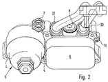
- Fig. 2
- eine perspektivische Ansicht auf den Träger nach Fig. 1 unter einem anderen Blickwinkel,
- Fig. 3
- eine Ansicht auf den Verbindungsflansch des Trägers nach dem Pfeil III in Fig. 1,
- Fig. 4
- eine Ansicht auf einen Träger nach Fig. 1 ohne von diesem aufzunehmende Aggregate in einer Ansicht von oben,
- Fig. 5
- einen Schnitt durch den Träger nach Linie V-V in Fig. 1,
- Fig. 6
- einen Schnitt durch den Träger nach Fig. 1 entlang der Linie VI-VI,
- Fig. 7
- einen Schnitt durch den Träger nach Fig. 1 entlang der Linie VII-VII,
- Fig. 8
- einen Schnitt durch den Träger entlang der Linie VIII-VIII in Fig. 1.
- Fig. 1
- 3 shows a perspective view of a carrier which has already been completed with all the units to be used,
- Fig. 2
- 2 shows a perspective view of the carrier according to FIG. 1 from a different perspective,
- Fig. 3
- 2 shows a view of the connecting flange of the carrier according to arrow III in FIG. 1,
- Fig. 4
- 1 without a unit to be picked up by the carrier in a view from above,
- Fig. 5
- 2 shows a section through the carrier according to line VV in FIG. 1,
- Fig. 6
- 2 shows a section through the carrier according to FIG. 1 along the line VI-VI,
- Fig. 7
- 2 shows a section through the carrier according to FIG. 1 along the line VII-VII,
- Fig. 8
- a section through the carrier along the line VIII-VIII in Fig. 1st
Ein Trägerteil 1 ist ein kompaktes im Guß hergestelltes Urformteil,
das lediglich an Anschluß- und Aufnahmeflächenbereichen
bearbeitet ist. Dieses Trägerteil 1 wird über eine
Verbindungsfläche 2 eines an ihm vorgesehenen Verbindungsflansches
3 an einen Anschlußbereich eines in der Zeichnung
nicht dargestellten Kurbelgehäuses dicht angesetzt. Dieses
dichte Ansetzen erfolgt über in Befestigungsbohrungen 4 des
Trägerteiles 1 einzusetzende nicht dargestellte Spannschrauben.A carrier part 1 is a compact, cast part,
that only at connection and receiving surface areas
is processed. This carrier part 1 is a
Das Trägerteil 1 besitzt Aufnahmen für ein Ölfilter 5, einen
Ölkühler 6, ein Druckmeß- bzw. Warngerät 7 sowie ein Druckregelventil
8. The carrier part 1 has receptacles for an
Die Aufnahme für das Ölfilter 5 bildet bereits einen Teil
des Filtergehäuses, von dem ein Deckel 9 zum Austausch eines
Filterelementes 10 abnehmbar ist.The receptacle for the
Der Ölkühler 6 ist innerhalb eines quaderförmigen an einer
Breitseite offenen Gehäuse untergebracht. Seine Funktionsteile
besitzen einen an sich bekannten Aufbau, weshalb
hierauf an dieser Stelle nicht weiter eingegangen werden
soll. Von Bedeutung für die vorliegende Erfindung ist lediglich
der Anschluß des die Funktionsteile beinhaltenden Gehäuses
des Ölkühlers 6 an das Trägerteil 1.The
Dieser Anschluß erfolgt lediglich in einer Ebene, indem dort
Verbindungsflächen 11 des Trägerteiles 1 gegenüber entsprechenden
Anschlagstellen an dem Ölkühler 6 verspannt werden.
Diese Verspannung erfolgt über in die Befestigungsbohrungen
4 eingreifende Spannschrauben mit einer Gewindeverankerung
in dem Kurbelgehäuse. Mit dem Verspannen des Ölkühlers 6 gegenüber
dem Trägerteil 1 wird damit gleichzeitig das Trägerteil
1 fest gegenüber dem Kurbelgehäuse verspannt. An dem
Gehäuse des Ölkühlers 6 sind in Flanschen 12, in denen
Hauptbohrungen 13 zur Aufnahme der in die Befestigungsbohrungen
4 einzuführenden Spannschrauben vorgesehen sind, zusätzlich
noch Hilfsbohrungen 13 angebracht, denen entsprechende
Hilfsbohrungen 14 in dem Trägerteil 1 zugeordnet
sind. In diese Hilfsbohrungen (13, 14) greift jeweils eine
Hilfsschraube 15 ein. Durch zwei derartige Hilfsschrauben 15
wird der Ölkühler 6 provisorisch an dem Trägerteil 1 befestigt,
um bereits vor der Montage des Trägerteils 1 an das
Kurbelgehäuse eine geschlossen handhabbare Einheit aus Ölkühler
6 und Trägerteil 1 zu besitzen. Die endgültige dichte
Verspannung zwischen dem Ölkühler 6 und dem Trägerteil 1 erfolgt
allerdings erst bei der Montage des Trägerteiles 1 an
das Kurbelgehäuse mit Hilfe in die Befestigungsbohrungen 4
eingreifender Spannschrauben. Hierdurch werden auf äußerst
rationelle Weise die notwendigen Verbindungen zwischen dem
Ölkühler 6 und dem Befestigungsteil 1 einerseits und dem Befestigungsteil
1 und dem Kurbelgehäuse andererseits durch
ein und die gleiche Verschraubung mit denselben Spannschrauben
erreicht.This connection is made only in one level by there
Connection surfaces 11 of the carrier part 1 opposite corresponding
Stop points on the
In die Anlageflächen 11 des Trägerteiles 1, auf die der Ölkühler
6 aufzusetzen ist, münden Ölversorgungskanäle 16 und
17 sowie Kühlwasserkanäle 18 und 19. Bei einer dichten Anlage
des Ölkühlers 6 an den Auflageflächen 11 ist damit ein
kompletter Anschluß des Ölkühlers 6 an das Trägerteil 1 auf
denkbar einfache Weise gegeben.In the contact surfaces 11 of the carrier part 1, on which the
Die Kühlwasserversorgungskanäle 18 und 19 führen über Stutzen
20 und 21 nach außerhalb des Trägerteiles 1. Die frei
nach außen auslaufenden Bereiche der Stutzen 20 und 21 sind
als Steckmuffen zum Einstecken von Anschlußrohrleitungen
ausgebildet. The cooling
Die Ölversorgungskanäle 16 und 17 führen in die Verbindungsfläche
2 des Trägerteiles 1. Dort geht der Ölversorgungskanal
16 in einen bei noch nicht montiertem Trägerteil 1 offenen
Ölversorgungskanal 22 über, während der Ölversorgungskanal
17 in einen gleichartigen davon getrennten Ölversorgungskanal
23 übergeht.The
Bei auf das Kurbelgehäuse montiertem Trägerteil 1 steht der
Versorgungskanal 22 mit einer dort vorgesehenen Öffnung in
Verbindung, durch die Schmieröl von einer beispielsweise an
einer anderen Stelle angebrachten Ölpumpe angeliefert wird.
Das in den Ölversorgungskanal 22 geförderte Öl gelangt durch
den hiermit in Verbindung stehenden Ölversorgungskanal 16 in
den Ölkühler 6, den es durch den Ölversorgungskanal 17 in
den sich daran anschließenden Ölversorgungskanal 23 hinein
verläßt.When mounted on the crankcase support member 1 is the
Die bei noch nicht montiertem Trägerteil 1 offenen Ölversorgungskanäle 22 und 23 sind bei auf das Kurbelgehäuse aufgesetztem Trägerteil 1 verschlossene Kanäle, wobei diese Form der Kanäle durch eine dichte Anlage an der betreffenden Gegenfläche des Kurbelgehäuses erreicht wird.The oil supply ducts open when the carrier part 1 is not yet installed 22 and 23 are when placed on the crankcase Carrier part 1 closed channels, this shape the channels through a dense contact on the relevant counter surface of the crankcase is reached.
Von dem Ölversorgungskanal 23 aus durchströmt das Schmieröl
das Ölfilter 5, das es in einem Ölabflußkanal 24 verläßt.
Dieser Ölabflußkanal 24 steht bei auf das Kurbelgehäuse montiertem
Trägerteil 1 mit einer entsprechenden Öffnung in der
Gehäusewand des Kurbelgehäuses in Verbindung, damit das gereinigte
Schmieröl von dort zu seinen Bestimmungsstellen
über geeignete Leitungskanäle geführt werden kann.The lubricating oil flows through from the
In eine Aufnahme 25 des Trägerteiles 1 ist ein Druckmeßgerät
7 für den Öldruck einsetzbar, wofür diese Aufnahme 25 über
eine Bohrung 26 mit dem Ölabflußkanal 24 verbunden ist.In a
Zwischen den an sich getrennten Ölversorgungskanälen 22 und
23 befindet sich eine als Bypass für den durch den Ölkühler
6 geführten Schmierölstrom dienende Bypassöffnung 27. Diese
wird dadurch erzeugt, daß ein Trennsteg 28 zwischen den Ölversorgungskanälen
22 und 23 geringfügig gegenüber der Verbindungsfläche
2 zurückgenommen ist. Die Bypassöffnung 27
stellt eine Drosselverbindung zwischen den beiden Ölversorgungskanälen
22 und 23 dar.Between the separate
Das bereits oben erwähnte Druckregelventil 8 für die Vorgabe
und Einhaltung eines bestimmten Öldruckes innerhalb beispielsweise
des Ölversorgungskanales 22 ist wie folgt aufgebaut
und innerhalb des Trägerteils 1 angeordnet.The
Eine hohlzylindrische Aufnahme 29 mit einer zu der Verbindungsfläche
2 parallelen Achse ist in das Trägerteil 1 eingeformt.
Diese Aufnahme 29 besitzt Öffnungen 30, 31 und 32,
deren Bedeutung noch erläutert wird. A hollow
Die Öffnung 30 liegt an dem Ende der Aufnahme 29 und erstreckt
sich in deren Achsrichtung. Diese Öffnung 30 wird
von einem federbelasteten Kolben 33 verschlossen gehalten,
solange der durch die Öffnung 30 auf den Kolben 33 ausgeübte
Druck unterhalb des vorgebbaren Schließdruckes des Kolbens
33 liegt. Die Öffnung 30 steht mit dem Ölversorgungskanal 22
in Verbindung.The
Bei einem Freigeben der Öffnung 30 durch den Kolben 33 entsteht
eine Verbindung zu der Öffnung 31, die wiederum in einen
Kanal 34 in der Verbindungsfläche des Trägerteiles 1
übergeht. Diesem Kanal 34 ist in der Anschlußfläche des Kurbelgehäuses
eine in das Kurbelgehäuse führende Öffnung zugeordnet,
so daß Schmieröl über diesen Weg in das Kurbelgehäuse
als Bypassstrom zurückfließen kann.When the
Die in der Aufnahme 29 für das Druckregelventil 8 weiterhin
noch vorhandene Öffnung 32 stellt eine Entlüftungsöffnung
für das Druckregelventil 8 dar. Diese Öffnung 32 geht in einen
Kanal 35 über, der ebenfalls bei montiertem Trägerteil 1
mit einer Öffnung in dem Kurbelgehäuse in Verbindung steht.
Auf diesem Wege kann somit eine Entlüftung des Druckregelventiles
in das Kurbelgehäuse hinein erfolgen.The continue in the
Die einzelnen Kanäle 22, 23, 24, 34 und 35 innerhalb der
Verbindungsfläche 2 des Trägerteiles 1 sind jeweils durch
flache diese Kanäle umgreifende Dichtungen 36 gegeneinander
getrennt. Die Dichtungen 36 sind bei montiertem Trägerteil 1
dicht gegenüber der betreffenden Anlagefläche des Kurbelgehäuses
verspannt. Ein komplett mit sämtlichen Aggregaten
versehenes Trägerteil 1 ist ein äußerst praktisch und rationell
handhabbares Ölfilter-Modul mit sämtlichen Ölversorgungs- und Behandlungsaggregaten integriert in dieses Modulteil.The
Der Ölkühler kann ein an sich bekannter kostengünstig herstellbarer Platten-Wärmetauscher sein.The oil cooler can be an inexpensive, known per se Plate heat exchangers.
Claims (10)
dadurch gekennzeichnet,
daß in das Trägerteil (1) ein Bypasskanal (27) für einen gedrosselten Bypass zu der Ölführung durch den Ölkühler (6) integriert ist.Carrier part flange-mountable to a crankcase of an internal combustion engine with receptacles for at least one filter and a cooler as units of the lubricating oil supply and treatment with flow channels opening into the connecting surface that can be placed on a wall area of the crankcase from the interior of the carrier part and having openings in the to the Connections of the wall area of the crankcase assigned to the support part can be brought into alignment with existing openings, the channels required for supplying and distributing lubricating oil between the aggregate parts being molded flow channels into the support part,
characterized,
that a bypass channel (27) for a throttled bypass to the oil flow through the oil cooler (6) is integrated in the carrier part (1).
dadurch gekennzeichnet,
daß in diesem ein Druckregelventil (8) für den Schmierölkreislauf vorgesehen ist. Carrier part according to claim 1,
characterized,
that a pressure control valve (8) is provided for the lubricating oil circuit.
dadurch gekennzeichnet,
daß die Form und Lage der eingeformten Strömungskanäle derart ist, daß die Strömungskanäle durch von außen hinterschnittfrei eingreifende Formteile bei einer Herstellung des Trägerteils (1) durch ein Urformverfahren ausformbar sind.Carrier part according to claim 1 or 2,
characterized,
that the shape and position of the molded-in flow channels is such that the flow channels can be shaped by molded parts which engage without undercut from the outside during manufacture of the carrier part (1) by means of an original molding process.
dadurch gekennzeichnet,
daß das Trägerteil (1) noch zusätzlich eine Aufnahme für ein Druckmeßgerät (7) besitzt.Carrier part according to one of the preceding claims,
characterized,
that the carrier part (1) also has a receptacle for a pressure measuring device (7).
dadurch gekennzeichnet,
daß in der Verbindungsfläche (2) zu dem Kurbelgehäuse offene Strömungskanäle (22, 23, 24, 34, 35) eingeformt sind, die erst durch eine Anlage des Trägerteils (1) an dem Kurbelgehäuse einen geschlossenen Strömungsquerschnitt erhalten.Carrier part according to one of the preceding claims,
characterized,
that open flow channels (22, 23, 24, 34, 35) are formed in the connecting surface (2) to the crankcase, which flow channels receive a closed flow cross-section only when the carrier part (1) rests on the crankcase.
dadurch gekennzeichnet,
daß die Ölversorgung des Ölkühlers (6) und des Ölfilters (5) ausschließlich durch Strömungskanäle (22, 23 und 24) in der Verbindungsfläche (2) des Trägerteils (1) erfolgt.Carrier part according to one of the preceding claims,
characterized,
that the oil supply to the oil cooler (6) and the oil filter (5) takes place exclusively through flow channels (22, 23 and 24) in the connecting surface (2) of the carrier part (1).
dadurch gekennzeichnet,
daß die Versorgung des Ölkühlers (6) mit Öl und Kühlwasser über in einer gemeinsamen Ebene des Trägerteils (1) liegende Zu- und Abführöffnungen (16, 17 bzw. 18, 19) erfolgt, daß diese Ebene etwa parallel zur Verbindungsfläche (2) des Trägerteils (1) verläuft und daß die Verbindung zwischen Ölkühler (6) und Trägerteil (1) einerseits und Trägerteil (1) und Kurbelgehäuse andererseits durch - diese drei Teile gemeinsam erfassende und dicht gegeneinander verspannende - Schrauben erfolgt.Carrier part according to one of the preceding claims,
characterized,
that the supply of the oil cooler (6) with oil and cooling water via in a common plane of the carrier part (1) lying supply and discharge openings (16, 17 and 18, 19) that this plane approximately parallel to the connecting surface (2) of the Carrier part (1) runs and that the connection between the oil cooler (6) and the carrier part (1) on the one hand and the carrier part (1) and the crankcase on the other hand takes place by means of screws which jointly grip these three parts and tighten tightly against one another.
dadurch gekennzeichnet,
daß um die Strömungskanäle (22, 23, 24, 34 und 35) in der Verbindungsfläche (2) des Trägerteils (1) und um die in der Ölkühler (6)-Anschlußebene liegenden Öffnungen (16, 17, 18, 19) Dichtungen (36 bzw. 37) zur dichten Anlage zwischen den aneinanderliegenden Verbindungsflächen eingesetzt sind.Carrier part according to one of the preceding claims,
characterized,
that around the flow channels (22, 23, 24, 34 and 35) in the connecting surface (2) of the carrier part (1) and around the openings in the oil cooler (6) connection plane (16, 17, 18, 19) seals ( 36 or 37) are used for tight contact between the adjoining connecting surfaces.
dadurch gekennzeichnet,
daß an dem Ölkühler (6) und dem Trägerteil (1) miteinander zusammenwirkende Hilfsbefestigungsmittel (14, 15) für eine provisorische Verbindung zwischen diesen beiden Teilen (1, 6) angebracht sind, daß diese Hilfsbefestigungsmittel (14, 15) unabhängig von Hauptbefestigungsmitteln (4) sind und gleichzeitig mit diesen wirksam sein können. Carrier part according to one of the preceding claims,
characterized,
that auxiliary fastening means (14, 15) cooperating with each other for a provisional connection between these two parts (1, 6) are attached to the oil cooler (6) and the carrier part (1), that these auxiliary fastening means (14, 15) are independent of main fastening means (4 ) and can be effective at the same time.
gekennzeichnet durch die Merkmale
characterized by the characteristics
Applications Claiming Priority (2)
| Application Number | Priority Date | Filing Date | Title |
|---|---|---|---|
| DE19626867A DE19626867A1 (en) | 1996-07-04 | 1996-07-04 | Carrier part that can be flanged onto a crankcase of an internal combustion engine for units for lubricating oil supply and treatment |
| DE19626867 | 1996-07-04 |
Publications (2)
| Publication Number | Publication Date |
|---|---|
| EP0816645A1 true EP0816645A1 (en) | 1998-01-07 |
| EP0816645B1 EP0816645B1 (en) | 2001-10-04 |
Family
ID=7798854
Family Applications (1)
| Application Number | Title | Priority Date | Filing Date |
|---|---|---|---|
| EP97110157A Expired - Lifetime EP0816645B1 (en) | 1996-07-04 | 1997-06-21 | Mounting bracket for aggregates of oil treatment and maintenace mounted on the block of an internal combustion engine |
Country Status (3)
| Country | Link |
|---|---|
| EP (1) | EP0816645B1 (en) |
| DE (2) | DE19626867A1 (en) |
| ES (1) | ES2164962T3 (en) |
Cited By (19)
| Publication number | Priority date | Publication date | Assignee | Title |
|---|---|---|---|---|
| FR2754562A1 (en) * | 1996-10-16 | 1998-04-17 | Daimler Benz Ag | INTERNAL COMBUSTION ENGINE HAVING CLAMPING FACES FOR CONNECTING FLUE AND RETURN PIPES FROM A COOLING WATER HEAT EXCHANGER |
| WO2001069050A3 (en) * | 2000-03-15 | 2001-12-06 | Mahle Filtersysteme Gmbh | Liquid filter, especially oil filter |
| WO2002034359A1 (en) * | 2000-10-25 | 2002-05-02 | Hengst Gmbh & Co. Kg | Module of units for an internal combustion engine |
| EP1211390A1 (en) * | 2000-12-01 | 2002-06-05 | Honda Giken Kogyo Kabushiki Kaisha | Unit housing for supporting auxiliary machineries of an engine |
| WO2006003336A1 (en) * | 2004-06-15 | 2006-01-12 | Renault S.A.S | Cooling system for a motor vehicle with water circuit and oil circuit |
| WO2006005328A1 (en) * | 2004-07-14 | 2006-01-19 | Hengst Gmbh & Co. Kg | Oil module with water pump and heat exchanger |
| EP1876406A1 (en) * | 2006-07-06 | 2008-01-09 | Behr GmbH & Co. KG | Heat exchanger filter assembly, in particular for a motor vehicle |
| WO2008009738A1 (en) | 2006-07-20 | 2008-01-24 | Mann+Hummel Gmbh | Liquid heat exchanger unit |
| JP2008533368A (en) * | 2005-03-18 | 2008-08-21 | マーレ インターナショナル ゲゼルシャフト ミット ベシュレンクテル ハフツング | Filter / cooler combination unit for liquid |
| EP2177722A2 (en) * | 2008-10-14 | 2010-04-21 | Valeo Systemes Thermiques | Valve housing attachable to a vehicle cooling module, vehicle cooling module and combinaison thereof |
| CN101705853A (en) * | 2009-11-27 | 2010-05-12 | 奇瑞汽车股份有限公司 | Automotive engine lubrication cooling device |
| CN101915141B (en) * | 2003-09-23 | 2013-03-27 | 亨格斯特两合公司 | Oil module for an internal combustion engine |
| WO2013058865A1 (en) * | 2011-10-21 | 2013-04-25 | Caterpillar Inc. | Apparatus and method for replacing an oil pressure regulating assembly and a high pressure relief valve assembly |
| EP2532848A3 (en) * | 2011-06-06 | 2013-06-05 | MAHLE International GmbH | Filter and cooling device |
| CN103147819A (en) * | 2013-02-25 | 2013-06-12 | 隆鑫通用动力股份有限公司 | Engine oil cooling structure assembly and engine thereof |
| US20130180496A1 (en) * | 2012-01-12 | 2013-07-18 | Chrysler Group Llc | Stepped oil-cooler |
| WO2015058890A1 (en) * | 2013-10-23 | 2015-04-30 | Mann+Hummel Gmbh | Oil filter module and control device for an engine oil circuit |
| US20180179927A1 (en) * | 2016-12-28 | 2018-06-28 | Kubota Corporation | Engine |
| CN110056407A (en) * | 2019-04-10 | 2019-07-26 | 广西玉柴机器股份有限公司 | Dispensing body structure |
Families Citing this family (14)
| Publication number | Priority date | Publication date | Assignee | Title |
|---|---|---|---|---|
| DE10028159A1 (en) | 2000-06-07 | 2001-12-13 | Mann & Hummel Filter | Oil module for an internal combustion engine |
| DE10040669A1 (en) * | 2000-08-19 | 2002-02-28 | Volkswagen Ag | Vehicle drive device has oil radiator and filter module offset from engine on frame towards main body of vehicle |
| DE10159106A1 (en) * | 2001-12-01 | 2003-06-18 | Porsche Ag | Internal combustion engine |
| DE20206616U1 (en) * | 2002-04-26 | 2003-09-04 | Hengst Gmbh & Co Kg | Cast component with angled groove has groove with side walls parallel to direction of deformation from base to mouth of groove |
| DE20312318U1 (en) * | 2003-08-09 | 2004-12-16 | Hengst Gmbh & Co.Kg | Liquid filter for an internal combustion engine |
| DE102004014787A1 (en) * | 2004-03-24 | 2005-10-13 | Mann + Hummel Gmbh | oil module |
| DE202004015748U1 (en) * | 2004-10-12 | 2006-02-23 | Hengst Gmbh & Co.Kg | Oil module for internal combustion engine has seals for connecting holes extending in common sealing plane and in form of single seal as flat gasket |
| DE202004016183U1 (en) * | 2004-10-18 | 2006-03-02 | Hengst Gmbh & Co.Kg | Heat exchanger for combustion engine with inlet and discharge openings for lubricant oil employs water as cooling agent of combustion engine whereby a mating surface is connected to crankcase of combustion engine |
| DE202005014632U1 (en) * | 2005-09-15 | 2007-02-01 | Hengst Gmbh & Co.Kg | Oil/water heat exchanger for internal combustion engine, has channel, which is provided in section in which valve is arranged, where channel is aligned parallel to connection surface at specific angle |
| DE102008031684B4 (en) | 2008-07-04 | 2020-02-06 | Mahle International Gmbh | cooling device |
| DE102008052259A1 (en) * | 2008-10-18 | 2010-04-22 | Mahle International Gmbh | filtering device |
| DE102011100385A1 (en) * | 2011-05-04 | 2012-11-08 | Volkswagen Aktiengesellschaft | Fluid cooling and filtering module for conduit device of cooling and/or lubricating system for internal combustion engine of motor car, has fluid cooler whose bypass channel defines predetermined leakage during normal operation of module |
| DE102016010391A1 (en) * | 2016-08-30 | 2018-03-01 | Mann + Hummel Gmbh | Connection flange of a fluid-carrying device and fluid-carrying device with at least one connection flange |
| DE102021130151A1 (en) | 2021-11-18 | 2023-05-25 | Audi Aktiengesellschaft | Drive device for an electrified vehicle axle |
Citations (5)
| Publication number | Priority date | Publication date | Assignee | Title |
|---|---|---|---|---|
| US3223197A (en) * | 1960-06-08 | 1965-12-14 | Gen Motors Corp | Oil pump and cooler assembly for an internal combustion engine |
| GB2132693A (en) * | 1980-01-21 | 1984-07-11 | Cummins Engine Co Inc | Lubrication oil filter mounting bracket |
| JPS6217594A (en) * | 1985-07-12 | 1987-01-26 | Nippon Denso Co Ltd | Heat exchanger |
| DE3803546A1 (en) * | 1987-02-06 | 1988-08-18 | Honda Motor Co Ltd | COOLING SYSTEM FOR WATER COOLING MOTOR OIL OF A MOTOR VEHICLE |
| DE29602434U1 (en) * | 1995-02-18 | 1996-06-20 | Glacier Metal Co Ltd | Liquid conditioning arrangement with temperature control |
Family Cites Families (3)
| Publication number | Priority date | Publication date | Assignee | Title |
|---|---|---|---|---|
| US4426965A (en) * | 1982-02-11 | 1984-01-24 | Cummins Engine Company, Inc. | Unitized oil cooler and filter assembly |
| DE4242997C1 (en) * | 1992-12-18 | 1994-04-14 | Hengst Walter Gmbh & Co Kg | Internal combustion engine with lubricating oil filter - has housing with connecting flange and sealing strips for filter, filter being incorporated with base on outside of connecting flange |
| DE4400952C1 (en) * | 1994-01-14 | 1995-05-24 | Daimler Benz Ag | Housing cover for an internal combustion engine |
-
1996
- 1996-07-04 DE DE19626867A patent/DE19626867A1/en not_active Ceased
-
1997
- 1997-06-21 ES ES97110157T patent/ES2164962T3/en not_active Expired - Lifetime
- 1997-06-21 DE DE59704758T patent/DE59704758D1/en not_active Expired - Lifetime
- 1997-06-21 EP EP97110157A patent/EP0816645B1/en not_active Expired - Lifetime
Patent Citations (5)
| Publication number | Priority date | Publication date | Assignee | Title |
|---|---|---|---|---|
| US3223197A (en) * | 1960-06-08 | 1965-12-14 | Gen Motors Corp | Oil pump and cooler assembly for an internal combustion engine |
| GB2132693A (en) * | 1980-01-21 | 1984-07-11 | Cummins Engine Co Inc | Lubrication oil filter mounting bracket |
| JPS6217594A (en) * | 1985-07-12 | 1987-01-26 | Nippon Denso Co Ltd | Heat exchanger |
| DE3803546A1 (en) * | 1987-02-06 | 1988-08-18 | Honda Motor Co Ltd | COOLING SYSTEM FOR WATER COOLING MOTOR OIL OF A MOTOR VEHICLE |
| DE29602434U1 (en) * | 1995-02-18 | 1996-06-20 | Glacier Metal Co Ltd | Liquid conditioning arrangement with temperature control |
Non-Patent Citations (1)
| Title |
|---|
| PATENT ABSTRACTS OF JAPAN vol. 011, no. 191 (M - 600) 19 June 1987 (1987-06-19) * |
Cited By (25)
| Publication number | Priority date | Publication date | Assignee | Title |
|---|---|---|---|---|
| FR2754562A1 (en) * | 1996-10-16 | 1998-04-17 | Daimler Benz Ag | INTERNAL COMBUSTION ENGINE HAVING CLAMPING FACES FOR CONNECTING FLUE AND RETURN PIPES FROM A COOLING WATER HEAT EXCHANGER |
| WO2001069050A3 (en) * | 2000-03-15 | 2001-12-06 | Mahle Filtersysteme Gmbh | Liquid filter, especially oil filter |
| US6833066B2 (en) | 2000-03-15 | 2004-12-21 | Mahle Filtersysteme Gmbh | Liquid filter, especially oil filter |
| WO2002034359A1 (en) * | 2000-10-25 | 2002-05-02 | Hengst Gmbh & Co. Kg | Module of units for an internal combustion engine |
| US6884348B2 (en) | 2000-10-25 | 2005-04-26 | Hengst Gmbh & Co. Kg | Module of units for an internal combustion engine |
| EP1211390A1 (en) * | 2000-12-01 | 2002-06-05 | Honda Giken Kogyo Kabushiki Kaisha | Unit housing for supporting auxiliary machineries of an engine |
| CN101915141B (en) * | 2003-09-23 | 2013-03-27 | 亨格斯特两合公司 | Oil module for an internal combustion engine |
| WO2006003336A1 (en) * | 2004-06-15 | 2006-01-12 | Renault S.A.S | Cooling system for a motor vehicle with water circuit and oil circuit |
| WO2006005328A1 (en) * | 2004-07-14 | 2006-01-19 | Hengst Gmbh & Co. Kg | Oil module with water pump and heat exchanger |
| JP2008533368A (en) * | 2005-03-18 | 2008-08-21 | マーレ インターナショナル ゲゼルシャフト ミット ベシュレンクテル ハフツング | Filter / cooler combination unit for liquid |
| EP1876406A1 (en) * | 2006-07-06 | 2008-01-09 | Behr GmbH & Co. KG | Heat exchanger filter assembly, in particular for a motor vehicle |
| WO2008009738A1 (en) | 2006-07-20 | 2008-01-24 | Mann+Hummel Gmbh | Liquid heat exchanger unit |
| EP2177722A2 (en) * | 2008-10-14 | 2010-04-21 | Valeo Systemes Thermiques | Valve housing attachable to a vehicle cooling module, vehicle cooling module and combinaison thereof |
| EP2177722A3 (en) * | 2008-10-14 | 2010-06-02 | Valeo Systemes Thermiques | Valve housing attachable to a vehicle cooling module, vehicle cooling module and combinaison thereof |
| CN101705853A (en) * | 2009-11-27 | 2010-05-12 | 奇瑞汽车股份有限公司 | Automotive engine lubrication cooling device |
| EP2532848A3 (en) * | 2011-06-06 | 2013-06-05 | MAHLE International GmbH | Filter and cooling device |
| WO2013058865A1 (en) * | 2011-10-21 | 2013-04-25 | Caterpillar Inc. | Apparatus and method for replacing an oil pressure regulating assembly and a high pressure relief valve assembly |
| US8925196B2 (en) | 2011-10-21 | 2015-01-06 | Caterpillar Inc. | Apparatus and method for replacing an oil pressure regulating assembly and a high pressure relief valve assembly |
| US20130180496A1 (en) * | 2012-01-12 | 2013-07-18 | Chrysler Group Llc | Stepped oil-cooler |
| CN103147819A (en) * | 2013-02-25 | 2013-06-12 | 隆鑫通用动力股份有限公司 | Engine oil cooling structure assembly and engine thereof |
| WO2015058890A1 (en) * | 2013-10-23 | 2015-04-30 | Mann+Hummel Gmbh | Oil filter module and control device for an engine oil circuit |
| US20180179927A1 (en) * | 2016-12-28 | 2018-06-28 | Kubota Corporation | Engine |
| US10837328B2 (en) * | 2016-12-28 | 2020-11-17 | Kubota Corporation | Engine |
| CN110056407A (en) * | 2019-04-10 | 2019-07-26 | 广西玉柴机器股份有限公司 | Dispensing body structure |
| CN110056407B (en) * | 2019-04-10 | 2022-05-24 | 广西玉柴机器股份有限公司 | Ligand structure |
Also Published As
| Publication number | Publication date |
|---|---|
| EP0816645B1 (en) | 2001-10-04 |
| DE19626867A1 (en) | 1998-01-29 |
| DE59704758D1 (en) | 2001-11-08 |
| ES2164962T3 (en) | 2002-03-01 |
Similar Documents
| Publication | Publication Date | Title |
|---|---|---|
| EP0816645B1 (en) | Mounting bracket for aggregates of oil treatment and maintenace mounted on the block of an internal combustion engine | |
| DE2417925C2 (en) | Liquid-cooled multi-cylinder internal combustion engine | |
| EP1751411B1 (en) | Optimized oil cooling system for an internal combustion engine | |
| DE19809124A1 (en) | Control device for the cooling and heating circuit of an internal combustion engine | |
| DE69909703T2 (en) | Anti-foam sheet of an internal combustion engine | |
| DE19741861B4 (en) | Device for controlling the cooling water circuit for an internal combustion engine | |
| DE19635534C2 (en) | Timing cover for an internal combustion engine | |
| DE19647299C1 (en) | Control housing for an internal combustion engine | |
| AT506309A4 (en) | Plate cooler for fluid i.e. hydraulic oil, has distribution box, and extruded profile plate body that opens out into collection chamber via receiving slot, where chamber is in connection with fluid channel | |
| DE3520876C1 (en) | Device for feeding lubricating oil to the friction areas of a cam shaft. | |
| DE19856770B4 (en) | Cooling system for an internal combustion engine | |
| EP0668440B1 (en) | Internal combustion engine | |
| DE10393269B4 (en) | Cooling device for a motorized vehicle | |
| DE1934193C3 (en) | Oil cooler training and fastening together with an oil filter in the water-cooled lubricating oil circuit of an internal combustion engine | |
| DE19741449A1 (en) | Support console for internal combustion engine | |
| EP1774152A1 (en) | Oil module with water pump and heat exchanger | |
| DE4342799C2 (en) | Oil-cooled reciprocating internal combustion engine | |
| DE4400953C2 (en) | Lube oil device for an internal combustion engine | |
| EP0998624B1 (en) | Conditioning unit for lubricating oil | |
| DE102005055580A1 (en) | Internal combustion engine fluid ducting has ducts for oil, air inlet and coolant formed in sections with plug in connections to engine block | |
| DE19633485B4 (en) | Liquid-cooled internal combustion engine | |
| EP2043754A1 (en) | Liquid heat exchanger unit | |
| DE19546262C1 (en) | Vehicle-heater | |
| WO2007014552A2 (en) | Ventilation module for an internal combustion engine | |
| DE2816902A1 (en) | IMPROVED TWO-STROKE ENGINE |
Legal Events
| Date | Code | Title | Description |
|---|---|---|---|
| PUAI | Public reference made under article 153(3) epc to a published international application that has entered the european phase |
Free format text: ORIGINAL CODE: 0009012 |
|
| AK | Designated contracting states |
Kind code of ref document: A1 Designated state(s): DE ES FR GB IT |
|
| 17P | Request for examination filed |
Effective date: 19980704 |
|
| AKX | Designation fees paid |
Free format text: DE ES FR GB IT |
|
| RBV | Designated contracting states (corrected) |
Designated state(s): DE ES FR GB IT |
|
| RAP1 | Party data changed (applicant data changed or rights of an application transferred) |
Owner name: DAIMLERCHRYSLER AG Owner name: KNECHT FILTERWERKE GMBH |
|
| RAP1 | Party data changed (applicant data changed or rights of an application transferred) |
Owner name: DAIMLERCHRYSLER AG Owner name: MAHLE FILTERSYSTEME GMBH |
|
| 17Q | First examination report despatched |
Effective date: 20000814 |
|
| GRAG | Despatch of communication of intention to grant |
Free format text: ORIGINAL CODE: EPIDOS AGRA |
|
| GRAG | Despatch of communication of intention to grant |
Free format text: ORIGINAL CODE: EPIDOS AGRA |
|
| GRAH | Despatch of communication of intention to grant a patent |
Free format text: ORIGINAL CODE: EPIDOS IGRA |
|
| GRAH | Despatch of communication of intention to grant a patent |
Free format text: ORIGINAL CODE: EPIDOS IGRA |
|
| GRAA | (expected) grant |
Free format text: ORIGINAL CODE: 0009210 |
|
| AK | Designated contracting states |
Kind code of ref document: B1 Designated state(s): DE ES FR GB IT |
|
| REF | Corresponds to: |
Ref document number: 59704758 Country of ref document: DE Date of ref document: 20011108 |
|
| ET | Fr: translation filed | ||
| REG | Reference to a national code |
Ref country code: GB Ref legal event code: IF02 |
|
| GBT | Gb: translation of ep patent filed (gb section 77(6)(a)/1977) |
Effective date: 20011214 |
|
| REG | Reference to a national code |
Ref country code: ES Ref legal event code: FG2A Ref document number: 2164962 Country of ref document: ES Kind code of ref document: T3 |
|
| PLBE | No opposition filed within time limit |
Free format text: ORIGINAL CODE: 0009261 |
|
| STAA | Information on the status of an ep patent application or granted ep patent |
Free format text: STATUS: NO OPPOSITION FILED WITHIN TIME LIMIT |
|
| 26N | No opposition filed | ||
| PGFP | Annual fee paid to national office [announced via postgrant information from national office to epo] |
Ref country code: IT Payment date: 20130626 Year of fee payment: 17 |
|
| PGFP | Annual fee paid to national office [announced via postgrant information from national office to epo] |
Ref country code: ES Payment date: 20130724 Year of fee payment: 17 Ref country code: DE Payment date: 20130902 Year of fee payment: 17 |
|
| PGFP | Annual fee paid to national office [announced via postgrant information from national office to epo] |
Ref country code: FR Payment date: 20130719 Year of fee payment: 17 Ref country code: GB Payment date: 20130701 Year of fee payment: 17 |
|
| REG | Reference to a national code |
Ref country code: DE Ref legal event code: R119 Ref document number: 59704758 Country of ref document: DE |
|
| GBPC | Gb: european patent ceased through non-payment of renewal fee |
Effective date: 20140621 |
|
| REG | Reference to a national code |
Ref country code: FR Ref legal event code: ST Effective date: 20150227 |
|
| REG | Reference to a national code |
Ref country code: DE Ref legal event code: R119 Ref document number: 59704758 Country of ref document: DE Effective date: 20150101 |
|
| PG25 | Lapsed in a contracting state [announced via postgrant information from national office to epo] |
Ref country code: IT Free format text: LAPSE BECAUSE OF NON-PAYMENT OF DUE FEES Effective date: 20140621 Ref country code: DE Free format text: LAPSE BECAUSE OF NON-PAYMENT OF DUE FEES Effective date: 20150101 |
|
| PG25 | Lapsed in a contracting state [announced via postgrant information from national office to epo] |
Ref country code: GB Free format text: LAPSE BECAUSE OF NON-PAYMENT OF DUE FEES Effective date: 20140621 Ref country code: FR Free format text: LAPSE BECAUSE OF NON-PAYMENT OF DUE FEES Effective date: 20140630 |
|
| REG | Reference to a national code |
Ref country code: ES Ref legal event code: FD2A Effective date: 20150729 |
|
| PG25 | Lapsed in a contracting state [announced via postgrant information from national office to epo] |
Ref country code: ES Free format text: LAPSE BECAUSE OF NON-PAYMENT OF DUE FEES Effective date: 20140622 |