EP0816630B1 - Méthode et système d'estimation en temps réel d'au moins un paramètre lié au comportement d'un outil de fond de puits - Google Patents
Méthode et système d'estimation en temps réel d'au moins un paramètre lié au comportement d'un outil de fond de puits Download PDFInfo
- Publication number
- EP0816630B1 EP0816630B1 EP97401298A EP97401298A EP0816630B1 EP 0816630 B1 EP0816630 B1 EP 0816630B1 EP 97401298 A EP97401298 A EP 97401298A EP 97401298 A EP97401298 A EP 97401298A EP 0816630 B1 EP0816630 B1 EP 0816630B1
- Authority
- EP
- European Patent Office
- Prior art keywords
- model
- string
- reduced
- displacement
- parameters
- Prior art date
- Legal status (The legal status is an assumption and is not a legal conclusion. Google has not performed a legal analysis and makes no representation as to the accuracy of the status listed.)
- Expired - Lifetime
Links
- 238000000034 method Methods 0.000 title claims description 26
- 238000005553 drilling Methods 0.000 claims description 39
- 238000006073 displacement reaction Methods 0.000 claims description 20
- 238000007906 compression Methods 0.000 claims description 15
- 238000005259 measurement Methods 0.000 claims description 14
- 230000001133 acceleration Effects 0.000 claims description 11
- 239000011159 matrix material Substances 0.000 claims description 9
- 238000001914 filtration Methods 0.000 claims description 8
- 230000008569 process Effects 0.000 claims description 8
- 230000006835 compression Effects 0.000 claims description 4
- 238000004441 surface measurement Methods 0.000 description 9
- 238000010586 diagram Methods 0.000 description 6
- 238000009434 installation Methods 0.000 description 6
- 238000010276 construction Methods 0.000 description 4
- 239000012530 fluid Substances 0.000 description 4
- 239000004459 forage Substances 0.000 description 3
- 238000012856 packing Methods 0.000 description 3
- 230000001629 suppression Effects 0.000 description 3
- 230000008859 change Effects 0.000 description 2
- 238000013016 damping Methods 0.000 description 2
- 235000021183 entrée Nutrition 0.000 description 2
- 230000007257 malfunction Effects 0.000 description 2
- 239000011435 rock Substances 0.000 description 2
- 238000005070 sampling Methods 0.000 description 2
- 230000003068 static effect Effects 0.000 description 2
- 238000012546 transfer Methods 0.000 description 2
- 230000002776 aggregation Effects 0.000 description 1
- 238000004220 aggregation Methods 0.000 description 1
- 238000004458 analytical method Methods 0.000 description 1
- 239000004020 conductor Substances 0.000 description 1
- 239000013256 coordination polymer Substances 0.000 description 1
- 230000003111 delayed effect Effects 0.000 description 1
- 238000012217 deletion Methods 0.000 description 1
- 230000037430 deletion Effects 0.000 description 1
- 238000000586 desensitisation Methods 0.000 description 1
- 230000009931 harmful effect Effects 0.000 description 1
- 238000002347 injection Methods 0.000 description 1
- 239000007924 injection Substances 0.000 description 1
- 238000000691 measurement method Methods 0.000 description 1
- 238000012545 processing Methods 0.000 description 1
- 230000001869 rapid Effects 0.000 description 1
- 230000009467 reduction Effects 0.000 description 1
- 238000000926 separation method Methods 0.000 description 1
- 239000002689 soil Substances 0.000 description 1
- 239000000243 solution Substances 0.000 description 1
- 239000003381 stabilizer Substances 0.000 description 1
- 238000013519 translation Methods 0.000 description 1
Images

Classifications
-
- E—FIXED CONSTRUCTIONS
- E21—EARTH OR ROCK DRILLING; MINING
- E21B—EARTH OR ROCK DRILLING; OBTAINING OIL, GAS, WATER, SOLUBLE OR MELTABLE MATERIALS OR A SLURRY OF MINERALS FROM WELLS
- E21B44/00—Automatic control systems specially adapted for drilling operations, i.e. self-operating systems which function to carry out or modify a drilling operation without intervention of a human operator, e.g. computer-controlled drilling systems; Systems specially adapted for monitoring a plurality of drilling variables or conditions
-
- E—FIXED CONSTRUCTIONS
- E21—EARTH OR ROCK DRILLING; MINING
- E21B—EARTH OR ROCK DRILLING; OBTAINING OIL, GAS, WATER, SOLUBLE OR MELTABLE MATERIALS OR A SLURRY OF MINERALS FROM WELLS
- E21B45/00—Measuring the drilling time or rate of penetration
Definitions
- the present invention relates to the field of measurements during drilling, in particular measures concerning the behavior of a drilling tool attached to the end of a drill string.
- the method according to the invention provides a solution for estimate in particular the amplitude of the vertical displacements of the drilling tool or the effort applied to the tool, said estimates being obtained by means of a calculation taking into account measurements made at the top of the drill string, i.e. substantially on the ground surface, generally by means of sensors or a fitting instrumented located in the vicinity of the means for rotating the lining.
- the information contained in the surface measurements does not alone are not enough to solve the problem posed, that is to say knowing the instantaneous movements of the tool by knowing the instantaneous movements of the surface trim.
- the surface measurement information must be supplemented by independent information of another kind which takes into account the structure of the drill string and its behavior between the bottom and the surface: this is the role of the knowledge which establishes the theoretical relationships between the bottom and the surface.
- the methodology of the present invention uses the conjunction of such a model, defined a priori, and surface measurements acquired in real time.
- the model can mainly take into account displacements and efforts vertical and said reduced model can calculate in real time the movement or the effort drilling tool vertical, said parameter measured at the surface being the vertical acceleration of the filling.
- the rotational speed measured on the surface can be a second parameter used in the scale model.
- the reduced model can be refined by self-adaptive filtering which minimizes the difference between an actual measurement of a parameter related to the displacement of the lining in surface and the corresponding output obtained by said reduced model.
- the filtering can take into account the tension force of the rods.
- the invention also relates to a system for estimating effective behavior. of a drilling tool attached to the end of a drill string and rotated in a well by means of drive located on the surface, in which an installation of calculation includes means for non-linear physical modeling of the drilling process based on general mechanical equations.
- the parameters of said means modeling are identified by taking into account the parameters of said well and said lining, and the calculation installation includes means for linearizing said model around an operating point, means for reducing said linearized model so to keep only some of the eigen modes of the state matrix of said model, means of calculating, in real time, the displacement of the drilling tool or the applied force on the tool, using the modeling means once linearized and reduced and the means measuring at least one parameter related to the displacement of the lining on the surface.
- the modeling means may only take into account the traction-compression, and the parameter can be one of the following: the rotation speed, vertical acceleration and packing tension.
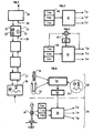
- FIG. 1 illustrates a drilling rig on which we will operate the invention.
- the surface installation comprises a lifting device 1 comprising a lifting tower 2, a winch 3 which allow the displacement of a drilling hook 4.
- Under the drill hook are suspended drive means 5 for rotating the assembly of the drill string 6 placed in the well 7.
- These drive means can be of the drive rod or kelly type coupled to a rotation table 8 and the mechanical motorizations, or of the type motorized drive head or "power swivel" suspended directly from the hook and guided longitudinally in the tower.
- the drill string 6 is conventionally constituted by rods of drilling 10, of part 11 commonly called BHA for "Bottom Hole Assembly” mainly comprising drill rods, a drilling tool 12 in contact with the land being drilled.
- BHA Bottom Hole Assembly
- the well 7 is filled with a fluid, called a drilling fluid, which circulates from the surface at the bottom through the inner channel of the drill string and rises to the surface by the annular space between the walls of the well and the drill string.
- an instrumented fitting 13 is inserted between the drive means and the top of the lining.
- This fitting allows measure the speed of rotation, the tensile force and the longitudinal vibrations of the top of the trim, and incidentally the couple. These so-called surface measurements are transmitted by cable or radio to an electronic recording, processing, display, not shown here.
- fitting 13 we can use other sensors such as a tachometer on the rotation table to measure the speed of rotation, a measurement of tension on the dead strand of hauling and possibly a device for measuring the torque on the motorized device, if the accuracy of the measurements obtained is sufficient.
- Part 11 of the BHA may more specifically include, drill collars, stabilizers, and a second instrumented fitting 14 which will only be used to control experimentally the present invention by allowing the comparison between the displacement of the drilling tool 12 actually measured by the instrumented fitting 14 and the estimated displacement thanks to the implementation of the present invention. So it is clear that the application of the present invention does not use an instrument fitting placed at the bottom of Wells.
- the driller who conducts a drilling operation with the devices described in the Figure 1 has three possible actions, which are therefore the possible control variables for driving, the weight on the tool which is adjusted by the winch which controls the hook position, rotation speed of the rotary table or equivalent, the flow of injected drilling fluid.
- the described model will treat the drill string as a one-dimensional element vertical. Displacements in vertical translation will be considered, displacements being neglected.
- FIG. 2 represents the block diagram of the traction-compression model. It is a classic model with finite differences which includes several meshes represented by blocks 20. Each mesh represents a part of the drill string, drill rods and drill collars. These are mass-spring-damping triples shown in the diagrams referenced 21, 22, 23. Each block is provided with two inputs and outputs represented by the pairs of arrows 24 and 25 which represent the input and output voltages and the vertical movement speeds of inputs and outputs. This representation shows the way to digitally connect several rods (or meshes) as we connect physically the packing rods.
- Block 26 represents the drilling rig. It is a collection of masses, of springs and friction.
- Block 27 represents the tool in its longitudinal behavior.
- Block 28 represents the law relating the movements of the drilling tool to the shape of the working face and the compressive strength of the rock. According to a position instantaneous vertical of the tool and the shape of the working face, the weight is determined acting on the tool.
- This model is validated using data recorded on site using the instrumented bottom and surface fittings.
- the tensile-compression model thus obtained is generally of high order, that is to say of the order of 50 to 100 to reproduce reality with sufficient finesse.
- the traction-compression model retains an order Student.
- the analysis of the eigen modes of the traction-compression model allows to quantify the contribution of each mode to the outputs of interest. Onne then keeps only the relevant modes; that is to say those who have an influence notable on the dynamic behavior represented by said outputs.
- the reduction method used is the singular disturbance method. It consists in keeping from the state matrix and from the command matrix, the lines and the columns corresponding to the modes to keep. To keep static gains, the modes Rapids are replaced by their static value, which has the consequence of introducing a direct matrix.
- the method assumes that the fast modes take their equilibrium in a time negligible, that is to say that they are established instantaneously (quasi-static hypothesis).
- FIG. 3 shows the block diagram of a loop-type estimation system opened.
- Block 40 shows diagrammatically the means for measuring surface parameters, here the voltage Tms and vertical acceleration Zms, the speed of rotation of the lining Vms measured at the table or at the motorized injection head.
- Block 41 represents the model which simulates the physical model of non-linear tension-compression by calculating the function transfer between the inputs (Vms, Zms) and the outputs Tes, Tef and Zef representing respectively the estimated tension on the lining at the surface, the estimated tension and the estimated vertical acceleration at the lower end of the packing in the well.
- the transfer function is always an approximation of reality and any mismatch between the model and the actual drilling process can create a discrepancy between the estimated values and the real values by integrating the differences. Also in the in most cases, it is advantageous to carry out a readjustment, or readjustment, using at least minus a comparison between the value of an estimated output and its value actually measured.
- the linear estimator is preferably readjusted from the surface tension.
- the estimation technique is based on the filtering principles of Luenberger and Kalman ("Automatic linear systems" by P. De Larminat and Y. Thomas-Flammarion science; Paris IV, 1975).
- the principle of a linear estimator can be illustrated by FIG. 4 where the measurement of the voltage Tms and the estimated value Tes and of the voltage are compared in the means 42, the difference between these two values being injected into an adapter 43 in real time.
- the objective here is to reconstruct as faithfully as possible the outputs rather than having an exact model. This is why we perform a registration state.
- state registration consists in weighting between the states predicted by the model at time t and the states reconstructed from the only measured outputs. This weighting is not a simple average, but it takes into account the degree of precision of the state estimates obtained by its two independent channels.
- Tes is the equivalent of a value filtered on the basis of a model: this is why we generally use the term filtering (filtering of Luenberger, Kalman filtering ).
- the state registration technique introduces a slaving of Tms measured on Tes estimated.
- the voltage T for carrying out the readjustment: it does not seem possible to readjust a large number of states from this measured. This is why, the nonlinear traction-compression model is not suitable in despite its greater precision.
- the reduced estimation model must, preferably meet the technological constraints of real time.
- Block 50 represents a physical model representing a rotary drilling process, for example illustrated in Figure 2. This model takes into account account for a determined operating situation, in particular by receiving the mechanical characteristics of the drill string used, symbolization referenced 51, well and surface conditions, symbolization referenced 52, and friction laws, symbolized by reference 53.
- Block 54 represents the main tension model once linearized and reduced as described above. All these steps gathered under the DF brace run in delayed time compared to the progress of the process rotary drilling, the other steps gathered under the TR brace are executed in time real.
- Block 55 is directly what has been called the estimator.
- Means of measure 56 placed on the top of the drill string give the measurements vertical acceleration, tension and speed of rotation at the top of the rods, i.e. surface. These surface measurements are taken into account in the estimator, as described above, to give an estimate of the displacement values of the tool drilling, in particular the vertical acceleration Zef from which the vertical displacement will be deducted of the drilling tool.
- the present invention is advantageously implemented on a construction site drilling in order to have as precise an estimate as possible of the vertical acceleration of the drilling tool in real time, using only surface measurements, in particular the vertical acceleration and the speed of rotation of conventional means of setting rotation of the drill string, and of a surface installation equipped with means electronic and computer. It is very interesting to have an estimate of the parameters background so as to detect, and even prevent known malfunctions, by example the so-called "bit bouncing" behavior characterized by a separation of the tool from the size face although the head of the drill string remains substantially stationary and a force of significant compression is applied to the tool. This can result in harmful effects on the life of the tools, on the increase of the mechanical fatigue of the drill string and the frequency of connection breaks.
Landscapes
- Life Sciences & Earth Sciences (AREA)
- Engineering & Computer Science (AREA)
- Geology (AREA)
- Mining & Mineral Resources (AREA)
- Physics & Mathematics (AREA)
- Environmental & Geological Engineering (AREA)
- Fluid Mechanics (AREA)
- General Life Sciences & Earth Sciences (AREA)
- Geochemistry & Mineralogy (AREA)
- Earth Drilling (AREA)
- Automatic Control Of Machine Tools (AREA)
Description
- on identifie les paramètres dudit modèle en prenant en compte les paramètres dudit puits et de ladite garniture,
- on linéarise ledit modèle autour d'un point de fonctionnement,
- on réduit ledit modèle linéarisé en ne conservant que certains des modes propres de la matrice d'état dudit modèle,
- on calcule, en temps réel, le déplacement de l'outil de forage ou l'effort appliqué sur l'outil, à l'aide du modèle réduit et d'au moins un paramètre mesuré en surface.
- la figure 1 représente schématiquement les moyens mis en oeuvre pour une opération de forage,
- la figure 2 représente un exemple de diagramme d'un modèle physique en traction-compression,
- la figure 3 représente un diagramme d'un estimateur en boucle ouverte,
- la figure 4 représente un diagramme d'un estimateur avec recalage,
- la figure 5 représente schématiquement la méthodologie de la constitution de l'estimateur selon l'invention.
- un appareil de forage comprenant une installation de levage,
- un ensemble d'entraínement: organe de régulation et motorisation,
- un ensemble de tiges,
- un ensemble de masses-tiges,
- un outil,
- un terrain représentant le contact outil/roche.
- x = X-X0
- X 0= valeurs des états au point de fonctionnement
- e = E-E0
- E 0= valeurs des entrées au point de fonctionnement
- s = S-S0
- S 0= valeurs des sorties au point de fonctionnement
- suppression des modes non ou peu observables sur les sorties mesurées,
- suppression des modes hautes fréquences, n'entrant pas dans la bande de fréquence de la commande ou de l'estimateur.
- il faut sauvegarder les modes propres de vibration en traction-compression qui sont prépondérants dans les sorties à ré estimer ;
- pour des raisons de cohérence et de stabilité numérique, il faut rejeter les modes de fréquences élevées supérieures à fmax = fe/2 où fe est la fréquence d'échantillonnage des entrées et des sorties.
- discrétisation du modèle réduit,
- discrétisation des filtres passe-haut,
- agrégation des filtres passe-haut et du modèle réduit, l'ensemble devient le modèle d'estimation,
- calcul des gains de recalage,
- construction de l'estimateur complet.
Claims (5)
- Méthode d'estimation du comportement effectif d'un outil de forage (12) fixé à l'extrémité d'une garniture de forage (6) et entraíné en rotation dans un puits (7) par des moyens d'entraínement (8) situés en surface, dans laquelle on utilise un modèle physique (50) non linéaire du processus de forage fondé sur des équations générales de la mécanique, caractérisée en ce que l'on effectue les étapes suivantes:on identifie les paramètres dudit modèle en prenant en compte les paramètres dudit puits et de ladite garniture (51, 52, 53),on linéarise ledit modèle autour d'un point de fonctionnement,on réduit ledit modèle linéarisé en ne conservant que certains des modes propres de la matrice d'état dudit modèle,on calcule, en temps réel, le déplacement de l'outil de forage ou l'effort appliqué sur l'outil, à l'aide du modèle réduit (54) et d'au moins un paramètre mesuré en surface, et en ce que ledit modèle prend en compte essentiellement les déplacements et les efforts verticaux et en ce que ledit modèle réduit calcule en temps réel le mouvement ou effort vertical de l'outil de forage, ledit paramètre mesuré en surface étant l'accélération verticale de la garniture.
- Méthode selon la des revendication 1, dans laquelle on calcule, en temps réel, le déplacement de l'outil de forage ou l'effort appliqué sur l'outil, à l'aide du modèle réduit et d'au moins les deux paramètres mesurés en surface : l'accélération verticale et la vitesse de rotation de la garniture.
- Méthode selon l'une des revendications 1 à 2, dans laquelle le modèle réduit est affiné par un filtrage auto adaptatif qui minimise la différence entre une mesure réelle d'un paramètre lié au déplacement de la garniture en surface et la sortie correspondante obtenue par ledit modèle réduit.
- Méthode selon la revendication 3, dans laquelle ledit filtrage prend en compte la force de tension mesurée en surface sur la garniture.
- Système d'estimation du comportement effectif d'un outil de forage (12) fixé à l'extrémité d'une garniture de forage (6) et entraíné en rotation dans un puits (7) par des moyens d'entraínement (8) situés en surface, dans lequel une installation de calcul (9) comporte des moyens de modélisation physique non linéaire du processus de forage fondé sur des équations générales de la mécanique, en ce que des paramètres desdits moyens de modélisation sont identifiés en prenant en compte les paramètres dudit puits et de ladite garniture, en ce que l'installation de calcul comporte des moyens de linéarisation dudit modèle autour d'un point de fonctionnement, des moyens de réduction dudit modèle linéarisé afin de ne conserver que certains des modes propres de la matrice d'état dudit modèle, des moyens de calcul, en temps réel, du déplacement de l'outil de forage ou de l'effort appliqué sur l'outil, à l'aide des moyens de modélisation une fois linéarisés et réduits et des moyens de mesure (13) d'au moins un paramètre lié au déplacement de la garniture en surface : la vitesse de rotation, l'accélération verticale et la tension de la garniture, dans lequel les moyens de modélisation ne prennent en compte que la traction et la compression.
Applications Claiming Priority (2)
| Application Number | Priority Date | Filing Date | Title |
|---|---|---|---|
| FR9607913 | 1996-06-24 | ||
| FR9607913A FR2750159B1 (fr) | 1996-06-24 | 1996-06-24 | Methode et systeme d'estimation en temps reel d'au moins un parametre lie au comportement d'un outil de fond de puits |
Publications (2)
| Publication Number | Publication Date |
|---|---|
| EP0816630A1 EP0816630A1 (fr) | 1998-01-07 |
| EP0816630B1 true EP0816630B1 (fr) | 2003-05-21 |
Family
ID=9493414
Family Applications (1)
| Application Number | Title | Priority Date | Filing Date |
|---|---|---|---|
| EP97401298A Expired - Lifetime EP0816630B1 (fr) | 1996-06-24 | 1997-06-09 | Méthode et système d'estimation en temps réel d'au moins un paramètre lié au comportement d'un outil de fond de puits |
Country Status (5)
| Country | Link |
|---|---|
| US (1) | US5844132A (fr) |
| EP (1) | EP0816630B1 (fr) |
| CA (1) | CA2209059C (fr) |
| FR (1) | FR2750159B1 (fr) |
| NO (1) | NO972931L (fr) |
Families Citing this family (15)
| Publication number | Priority date | Publication date | Assignee | Title |
|---|---|---|---|---|
| US6347292B1 (en) * | 1999-02-17 | 2002-02-12 | Den-Con Electronics, Inc. | Oilfield equipment identification method and apparatus |
| FR2792363B1 (fr) | 1999-04-19 | 2001-06-01 | Inst Francais Du Petrole | Methode et systeme de detection du deplacement longitudinal d'un outil de forage |
| AU2001296776A1 (en) * | 2000-10-10 | 2002-04-22 | Exxonmobil Upstream Research Company | Method for borehole measurement of formation properties |
| US6915686B2 (en) * | 2003-02-11 | 2005-07-12 | Optoplan A.S. | Downhole sub for instrumentation |
| EP2108166B1 (fr) | 2007-02-02 | 2013-06-19 | ExxonMobil Upstream Research Company | Modélisation et conception d'un système de forage de puits qui amortit les vibrations |
| EA018946B1 (ru) * | 2008-06-17 | 2013-11-29 | Эксонмобил Апстрим Рисерч Компани | Способы и системы для ослабления колебаний при бурении |
| WO2010059295A1 (fr) | 2008-11-21 | 2010-05-27 | Exxonmobil Upstream Research Company | Procédés et systèmes de modélisation, conception et conduite d'opérations de forage qui prennent en compte les vibrations |
| GB2466812B (en) | 2009-01-08 | 2011-10-19 | Schlumberger Holdings | Drillstring dynamics |
| MY158575A (en) * | 2009-08-07 | 2016-10-14 | Exxonmobil Upstream Res Co | Methods to estimate downhole drilling vibration indices from surface measurement |
| WO2011017626A1 (fr) * | 2009-08-07 | 2011-02-10 | Exxonmobil Upstream Research Company | Procédés pour estimer une amplitude de vibration de forage de fond de trou à partir d'une mesure de surface |
| US11225834B2 (en) | 2015-04-29 | 2022-01-18 | Halliburton Energy Services, Inc. | Systems and methods for sensorless state estimation, disturbance estimation, and model adaption for rotary steerable drilling systems |
| NL2016859B1 (en) * | 2016-05-30 | 2017-12-11 | Engie Electroproject B V | A method of and a device for estimating down hole speed and down hole torque of borehole drilling equipment while drilling, borehole equipment and a computer program product. |
| US10443334B2 (en) | 2017-05-19 | 2019-10-15 | Weatherford Technology Holdings Llc | Correction for drill pipe compression |
| WO2019119107A1 (fr) | 2017-12-23 | 2019-06-27 | Noetic Technologies Inc. | Système et procédé d'optimisation d'opérations de pose d'éléments tubulaires à l'aide de mesures et d'une modélisation en temps réel |
| EP3768944A4 (fr) * | 2018-03-23 | 2022-01-12 | ConocoPhillips Company | Sous-ensemble virtuel de fond de trou |
Family Cites Families (14)
| Publication number | Priority date | Publication date | Assignee | Title |
|---|---|---|---|---|
| US4845628A (en) * | 1986-08-18 | 1989-07-04 | Automated Decisions, Inc. | Method for optimization of drilling costs |
| US4794535A (en) * | 1986-08-18 | 1988-12-27 | Automated Decisions, Inc. | Method for determining economic drill bit utilization |
| FR2614360B1 (fr) * | 1987-04-27 | 1989-06-16 | Forex Neptune | Procede de mesure de la vitesse d'avancement d'un outil de forage |
| DE3715424C2 (de) * | 1987-05-08 | 1995-01-26 | Henkel Kgaa | Verwendung eines fetten Öles aus Helianthus annuus zur Herstellung von Fettsäure-Monoglyceriden |
| FR2645295B1 (fr) * | 1989-03-29 | 1994-06-10 | Renault | Dispositif de surveillance du fonctionnement d'un microprocesseur |
| FR2645205B1 (fr) * | 1989-03-31 | 1991-06-07 | Elf Aquitaine | Dispositif de representation auditive et/ou visuelle des phenomenes mecaniques dans un forage et utilisation du dispositif dans un procede de conduite d'un forage |
| FR2666845B1 (fr) * | 1990-09-14 | 1997-01-10 | Elf Aquitaine | Procede de conduite d'un forage. |
| GB2264562B (en) * | 1992-02-22 | 1995-03-22 | Anadrill Int Sa | Determination of drill bit rate of penetration from surface measurements |
| FR2688026B1 (fr) * | 1992-02-27 | 1994-04-15 | Institut Francais Petrole | Systeme et methode d'acquisition de donnees physiques liees a un forage en cours. |
| US5305836A (en) * | 1992-04-08 | 1994-04-26 | Baroid Technology, Inc. | System and method for controlling drill bit usage and well plan |
| GB9216740D0 (en) * | 1992-08-06 | 1992-09-23 | Schlumberger Services Petrol | Determination of drill bit rate of penetration from surface measurements |
| GB9218836D0 (en) * | 1992-09-05 | 1992-10-21 | Schlumberger Services Petrol | Method for determining weight on bit |
| NO315670B1 (no) * | 1994-10-19 | 2003-10-06 | Anadrill Int Sa | Fremgangsmåte og anordning for måling av boretilstander ved kombinasjon avnedihulls- og overflatemålinger |
| US5581024A (en) * | 1994-10-20 | 1996-12-03 | Baker Hughes Incorporated | Downhole depth correlation and computation apparatus and methods for combining multiple borehole measurements |
-
1996
- 1996-06-24 FR FR9607913A patent/FR2750159B1/fr not_active Expired - Fee Related
-
1997
- 1997-06-09 EP EP97401298A patent/EP0816630B1/fr not_active Expired - Lifetime
- 1997-06-23 US US08/880,858 patent/US5844132A/en not_active Expired - Lifetime
- 1997-06-23 NO NO972931A patent/NO972931L/no not_active Application Discontinuation
- 1997-06-23 CA CA002209059A patent/CA2209059C/fr not_active Expired - Fee Related
Also Published As
| Publication number | Publication date |
|---|---|
| CA2209059A1 (fr) | 1997-12-24 |
| NO972931L (no) | 1997-12-29 |
| FR2750159A1 (fr) | 1997-12-26 |
| FR2750159B1 (fr) | 1998-08-07 |
| NO972931D0 (no) | 1997-06-23 |
| EP0816630A1 (fr) | 1998-01-07 |
| US5844132A (en) | 1998-12-01 |
| CA2209059C (fr) | 2006-11-21 |
Similar Documents
| Publication | Publication Date | Title |
|---|---|---|
| EP0816629B1 (fr) | Méthode et système d'estimation en temps reel d'au moins un paramètre lié au déplacement d'un outil de forage | |
| EP1046781B1 (fr) | Méthode et système de détection du déplacement longitudinal d'un outil de forage | |
| CA2209059C (fr) | Methode et systeme d'estimation en temps reel d'au moins un parametre lie au comportement d'un outil de fond de puits | |
| Skinner et al. | Analysis and modelling of gravity-and piston coring based on soil mechanics | |
| FR2869067A1 (fr) | Systeme et procede de synthese de champ pour l'optimisation d'un dispositif de forage | |
| Macpherson et al. | A framework for transparency in drilling mechanics and dynamics measurements | |
| US8120357B2 (en) | Method and system for fluid characterization of a reservoir | |
| EP2836814A1 (fr) | Procédé de détermination de paramètres géomécaniques d'un échantillon de roche | |
| EP2817607B1 (fr) | Tete de mesure destinee a equiper un penetrometre dynamique et procede de mesure a l'aide d'une telle tete de mesure | |
| FR3039196A1 (fr) | ||
| US20210270120A1 (en) | Drilling evaluation based on coupled torsional vibrations | |
| Ueda et al. | Applicability of the generalized scaling law to a pile-inclined ground system subject to liquefaction-induced lateral spreading | |
| FR2611804A1 (fr) | Procede de controle des operations de forage d'un puits | |
| FR2614360A1 (fr) | Procede de mesure de la vitesse d'avancement d'un outil de forage | |
| EP0341109A1 (fr) | Méthode pour évaluer la teneur des roches sédimentaires en matière organique à partir de données enregistrées dans des puits par des sondes de diagraphie | |
| FR3035147A1 (fr) | ||
| JP6832211B2 (ja) | 地盤調査装置及び地盤調査方法 | |
| FR3034191A1 (fr) | Determination de pression de formation | |
| EP0505276A1 (fr) | Sonde pour déterminer notamment l'injectivité d'un puits pétrolier et procédé de mesures la mettant en oeuvre | |
| FR3076626A1 (fr) | Prediction de proprietes de roches sismiques en temps avance sur la base d'une analyse sismique 4d | |
| FR3021678A1 (fr) | Procede et dispositif de determination de la capacite portante d'un micropieu | |
| EP3502751A1 (fr) | Procédé de modelisation d'un bassin sédimentaire | |
| Wapenaar et al. | The wavelet transform as a tool for geophysical data integration | |
| FR2836572A1 (fr) | Procede pour la determination d'un indice de qualite spatiale de donnees regionalisees | |
| Wang et al. | Assessing the Impact of Borehole Coupling Materials on Shallow Downhole Fiber-Optic Distributed Acoustic Sensing (FO-DAS) Using Laboratory Simulations |
Legal Events
| Date | Code | Title | Description |
|---|---|---|---|
| PUAI | Public reference made under article 153(3) epc to a published international application that has entered the european phase |
Free format text: ORIGINAL CODE: 0009012 |
|
| AK | Designated contracting states |
Kind code of ref document: A1 Designated state(s): GB IT NL |
|
| 17P | Request for examination filed |
Effective date: 19980707 |
|
| AKX | Designation fees paid |
Free format text: GB IT NL |
|
| RBV | Designated contracting states (corrected) |
Designated state(s): GB IT NL |
|
| REG | Reference to a national code |
Ref country code: DE Ref legal event code: 8566 |
|
| 17Q | First examination report despatched |
Effective date: 20010309 |
|
| GRAH | Despatch of communication of intention to grant a patent |
Free format text: ORIGINAL CODE: EPIDOS IGRA |
|
| GRAH | Despatch of communication of intention to grant a patent |
Free format text: ORIGINAL CODE: EPIDOS IGRA |
|
| GRAA | (expected) grant |
Free format text: ORIGINAL CODE: 0009210 |
|
| AK | Designated contracting states |
Designated state(s): GB IT NL |
|
| REG | Reference to a national code |
Ref country code: GB Ref legal event code: FG4D Free format text: NOT ENGLISH |
|
| GBT | Gb: translation of ep patent filed (gb section 77(6)(a)/1977) |
Effective date: 20030521 |
|
| PGFP | Annual fee paid to national office [announced via postgrant information from national office to epo] |
Ref country code: NL Payment date: 20030627 Year of fee payment: 7 |
|
| PGFP | Annual fee paid to national office [announced via postgrant information from national office to epo] |
Ref country code: GB Payment date: 20030925 Year of fee payment: 7 |
|
| PLBE | No opposition filed within time limit |
Free format text: ORIGINAL CODE: 0009261 |
|
| STAA | Information on the status of an ep patent application or granted ep patent |
Free format text: STATUS: NO OPPOSITION FILED WITHIN TIME LIMIT |
|
| 26N | No opposition filed |
Effective date: 20040224 |
|
| PG25 | Lapsed in a contracting state [announced via postgrant information from national office to epo] |
Ref country code: GB Free format text: LAPSE BECAUSE OF NON-PAYMENT OF DUE FEES Effective date: 20040609 |
|
| PG25 | Lapsed in a contracting state [announced via postgrant information from national office to epo] |
Ref country code: NL Free format text: LAPSE BECAUSE OF NON-PAYMENT OF DUE FEES Effective date: 20050101 |
|
| GBPC | Gb: european patent ceased through non-payment of renewal fee |
Effective date: 20040609 |
|
| NLV4 | Nl: lapsed or anulled due to non-payment of the annual fee |
Effective date: 20050101 |
|
| PGFP | Annual fee paid to national office [announced via postgrant information from national office to epo] |
Ref country code: IT Payment date: 20070622 Year of fee payment: 11 |
|
| PG25 | Lapsed in a contracting state [announced via postgrant information from national office to epo] |
Ref country code: IT Free format text: LAPSE BECAUSE OF NON-PAYMENT OF DUE FEES Effective date: 20080609 |