EP0816193B1 - Nasswischarm einer Scheibenwischvorrichtung für Scheiben von Fahrzeugen - Google Patents
Nasswischarm einer Scheibenwischvorrichtung für Scheiben von Fahrzeugen Download PDFInfo
- Publication number
- EP0816193B1 EP0816193B1 EP19970109261 EP97109261A EP0816193B1 EP 0816193 B1 EP0816193 B1 EP 0816193B1 EP 19970109261 EP19970109261 EP 19970109261 EP 97109261 A EP97109261 A EP 97109261A EP 0816193 B1 EP0816193 B1 EP 0816193B1
- Authority
- EP
- European Patent Office
- Prior art keywords
- hose
- wiper arm
- fastening part
- wiper
- joint
- Prior art date
- Legal status (The legal status is an assumption and is not a legal conclusion. Google has not performed a legal analysis and makes no representation as to the accuracy of the status listed.)
- Expired - Lifetime
Links
- 239000012530 fluid Substances 0.000 title claims description 6
- 238000004140 cleaning Methods 0.000 title 1
- 238000005406 washing Methods 0.000 claims description 10
- 230000005489 elastic deformation Effects 0.000 claims 1
- 239000007788 liquid Substances 0.000 description 7
- 238000009434 installation Methods 0.000 description 2
- 238000010521 absorption reaction Methods 0.000 description 1
- 230000008878 coupling Effects 0.000 description 1
- 238000010168 coupling process Methods 0.000 description 1
- 238000005859 coupling reaction Methods 0.000 description 1
- 230000001627 detrimental effect Effects 0.000 description 1
- 238000006073 displacement reaction Methods 0.000 description 1
- 230000000694 effects Effects 0.000 description 1
- 238000004519 manufacturing process Methods 0.000 description 1
- 239000000463 material Substances 0.000 description 1
- 230000003252 repetitive effect Effects 0.000 description 1
- 238000007665 sagging Methods 0.000 description 1
- 239000007921 spray Substances 0.000 description 1
- 238000011144 upstream manufacturing Methods 0.000 description 1
Images


Classifications
-
- B—PERFORMING OPERATIONS; TRANSPORTING
- B60—VEHICLES IN GENERAL
- B60S—SERVICING, CLEANING, REPAIRING, SUPPORTING, LIFTING, OR MANOEUVRING OF VEHICLES, NOT OTHERWISE PROVIDED FOR
- B60S1/00—Cleaning of vehicles
- B60S1/02—Cleaning windscreens, windows or optical devices
- B60S1/04—Wipers or the like, e.g. scrapers
- B60S1/32—Wipers or the like, e.g. scrapers characterised by constructional features of wiper blade arms or blades
- B60S1/34—Wiper arms; Mountings therefor
- B60S1/3415—Wiper arms; Mountings therefor with means for supplying cleaning fluid to windscreen cleaners, e.g. washers
-
- B—PERFORMING OPERATIONS; TRANSPORTING
- B60—VEHICLES IN GENERAL
- B60S—SERVICING, CLEANING, REPAIRING, SUPPORTING, LIFTING, OR MANOEUVRING OF VEHICLES, NOT OTHERWISE PROVIDED FOR
- B60S1/00—Cleaning of vehicles
- B60S1/02—Cleaning windscreens, windows or optical devices
- B60S1/46—Cleaning windscreens, windows or optical devices using liquid; Windscreen washers
- B60S1/48—Liquid supply therefor
- B60S1/52—Arrangement of nozzles; Liquid spreading means
- B60S1/522—Arrangement of nozzles; Liquid spreading means moving liquid spreading means, e.g. arranged in wiper arms
Definitions
- the invention relates to a wet wiper arm of a windshield wiper device for windows of vehicles with the characteristics the preamble of claim 1.
- a wet wiper arm is known from DE 25 09 876 A1, in which a washer fluid line concealed in the towards the pane open cross-sectional profile of the wiper arm is guided along and the joint on the side facing the disc crossed between the fastening part and the joint part. in this connection is the end of the nozzle device opposite Washer fluid line with one on the fastening part concealed, dimensionally stable cable connector connected, from which another hose from Fastening part guided and to a pump or Storage container or the like can be connected.
- Another wet wiper arm with an essentially concealed one Hose guide on the wiper arm is from DE 41 34 980 A1 known. With this wet wiper arm, this is the nozzle device opposite end of the hose in the area of the Fastening part covered by this with the end of one through the hollow wiper shaft Washer fluid line connected. Concealed leadership of the The hose on the fastening part is in the area of the joint a lateral one between the fastening part and the joint part Groove provided in which the liquid line runs and that of a side cheek of the joint part or one that Fastening part covering cover is covered.
- Another wet wiper arm is known from DE 41 30 023 C2, where the hose for supplying one on the wiper arm attached washing nozzle with washing liquid on the outside of a Is laid or guided along the long side of the wiper arm.
- the hose is not covered, i.e. visible, which is disadvantageous for reasons of aerodynamics and style is.
- To hold the hose and the washing nozzle opposite part in the longitudinal direction of the fastening part is on both sides of the wiper arm joint, so on the side of the fastening part and the joint part, across open receptacles attached to the longitudinal direction of the hose, in which the hose is inserted.
- GB-A-2 263 394 shows a wet wiper arm with the features of the preamble of claim 1.
- the definition of Hose at the first location is done by a Spring through which the hose is passed. In the area of the joint, the hose is clipped in with the help of a clip Position held. On the side facing the wiper shaft of the joint, the hose is through a through hole passed through, which is recessed in the wiper carrier.
- the object of the invention is to provide a wet wiper arm Features of the preamble of the new patent claim 1 to develop in such a way that even with frequent Fold away the wiper arm from the window to be wiped This creates a protruding part on the underside of the wiper arm loop-shaped section of the hose is avoided.
- the hose at the first fixing point opposite side of between the fastener and Joint part formed joint in the manner of a strain relief at a second location on the fastener or / and on a cover cap of the fastening part is fixed, the further upstream part of the Hose on the side opposite the wiper arm joint the second location of the wiper arm or Fastening part are led away.
- the hose is thus on both sides of the joint between the fastening part and Joint part at the two fixing points at least clamped in its longitudinal direction, and also is the distance between the two clamping points bridging hose section in the operating position of the Wiper arm without or without substantial tension in the Distance between the two clamping points is tight. Therefore, the hose remains safely in its essential concealed arrangement on the wiper arm.
- the design of the Wet wiper arm according to the invention should be ensured that in Depending on the elasticity of the hose the distance between the two locations is at least as large that the limited by the two determination points Hose section which when folding away the joint part from the Resilient disc resists entering without doing so to experience a permanent disruptive elongation.
- a Such permanent elongation could occur after a long period of operation also cause the hose at the bottom of the Wiper arm emerges from the cross-sectional profile and is visible becomes.
- the clamping of the hose on the second determination point is brought about by the fact that alternately from one side wall of the hose channel Protrusions protrude into the hose channel and at the points the protrusions the opposite side wall of the Hose channel has a corresponding bulge.
- the size of the essential longitudinal guidance of the hose deviating lateral deflections kept relatively low, which is why a small installation space is required.
- the hose duct is also easy in terms of tools controllable, so that the manufacturing costs for the Fastening part or the cover cap not at all or only are negligibly higher.
- the nozzle device is there directly on the wiper arm or wiper blade or on one with the Wiper arm or component connected to the wiper blade.
- Such a component to which the nozzle device is attached can also be a wind deflector or a panel or a connecting part of the wiper arm and wiper blade or a Coupling piece between the two arms of a double wiper arm or the like.
- the nozzle device is the two Connection bridging section of the hose consequently relatively long, so that when the Joint part from the disc on this hose section related elastic elongation is relatively low and thus also a relatively low traction in this Hose section is created.
- a configuration according to claim 5 is recommended, according to which the Definition of the hose at the second location within one, preferably open on one long side, Hose channel takes place on the fastening part or on the Cover cap is provided.
- the advantage here is that the means necessary for clamping the hose can be provided in a space-saving manner within the hose duct can and that the hose is secure in the hose channel is held and managed.
- a thick-walled and relatively rigid The clamping force can be relatively large without the To deform the hose cross section excessively. In this Case a simple lateral deflection or a relatively large distance between several excursions sufficient to secure the hose to the fastener clamp.
- a further development of the invention is particularly preferred according to claim 6, after which the tube coming from the joint part after crossing the joint through a breakthrough in the Fastener from the bottom of the fastener too the top of which is passed through. This enables in anyway the concealed hose guide in the anyway existing space between the top of the fastener and the cap.
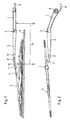
- the wiper arm shown in Fig. 1 is a so-called wet wiper arm. It essentially consists of a fastening part 1, the rotatable on a drivable wiper shaft is to be fastened and by means of a joint 2 a joint part 3 is connected. At the free end of the joint part 3 a wiper rod 4 is attached, the free End designed for pivotable connection with a wiper blade 5 is.
- the joint 2 serves that the joint part 3rd with wiper rod 4 in the direction of the window to be wiped 6 or from the window 6 to be wiped away.
- a pressure spring ensures that the wiper blade 5 with a certain force on the to be wiped Disc 6 rests.
- the spray nozzles are intended to If necessary, washing liquid on the window to be wiped 6 leave.
- An elastic hose 8 is intended for the nozzle device 7.
- the concealed along the wiper arm in the 6 open cross-sectional profile of the fastening part 1 and the joint part 3 is misplaced.
- the Hose 8 next to the receptacle 9 for the wiper shaft lengthways enters the fastening part 1 and on the opposite End below the wiper rod 4 from the joint part 3 exit.
- the nozzle device attached to the wiper rod 4 7 has a hose connector 10, which is below the wiper rod 4 and the end of the Hose 8 is attached.
- a holding device 11 is provided on the joint part 3, which the hose 8 a guide in the direction of Wiper rod 4 offers, but not as a strain relief in With regard to a tensile force acting on the hose 8 acts.
- the tube 8 is within the cross-sectional profile of the Wiper arm guided so that he the joint 2 at the bottom of the wiper arm.
- a second clamping point 13 of the hose 8 is direct provided on the fastening part 1 and is thus located on the other side of the joint 2.
- On this second Fixing point 13 is the hose 8 in the manner of a Strain relief set on the fastening part 1, so that the hose 8 in the operating position, d. H. in stretched Location of the wiper arm, in the distance between the two Fixing points 12, 13 without or without substantial tension is kept permanently taut.
- the wiper arm that is, the hinge part 3 with wiper rod 4, of the Fold disc 6 away. This is necessary, for example, if the pane 6 is cleaned by hand or if the wiper blade 5 or the wiper blade of the wiper blade 5 Wear reasons is replaced. Because the hose 8 crosses joint 2 on the underside of the wiper arm, extends when the wiper arm is folded away from the Disc 6 the distance between the two fixing points 12 and 13, so that the relevant hose section 14th undergoes elastic elongation, i.e. the hose section 14 is extended in the longitudinal direction.
- the fastening part 1 has an elongated shape with two ends, one end a receptacle 9 for the wiper shaft and at the other end a bearing 15 for forming the joint 2 can be seen.
- the fastening part has between the receptacle 9 and the bearing 15 1 an open towards the disc 6 U-like cross-sectional profile with a back 16, of which from itself the two side walls 17 and 18 in the direction of extend the window 6 to be wiped.
- Hose channel 19 for receiving and guiding the hose 8 is determined.
- the hose channel 19 is advantageous on a long side of the fastening part 1 within the Cross-sectional profile arranged so that one side wall 17 of the fastening part 1 also has a side wall 17 of the hose channel 19.
- the second side wall 20 of the in Direction to the disc 6 open hose channel 19 is additional molded onto the fastening part 1 and extends starting from the back 16, also in the direction of the windshield to be wiped 6 the hose channel 19 has an opening for the wiper shaft 21, through which the hose 8 approximately in the longitudinal direction the fastening part 1 emerges from the wiper arm and is led away from it.
- Fig. 3 is the second fixing point approximately in the central area 13 for the hose 8.
- the hose 8 At this Fixing point 13, which extends over a certain longitudinal range the fastening part 1 or the hose channel 19 extends, the hose 8 three times from its essential Longitudinally deflected laterally.
- the side Deflections are arranged alternately Projections 22 and opposite corresponding ones Bulges 23 brought about, which in the longitudinal direction of the Fastening part 1 considered, approximately at equal intervals are arranged from each other.
- the side wall 20 of the hose channel 19 has two projections 22, which protrude into the hose channel 19 in a nub-like manner. Is located approximately in the middle between these projections 22 this side wall 20 of the hose channel 19 has a bulge 23.
- the projections 22 and the corresponding bulges 23 are designed in this way and matched that the hose 8 without essential Cross-sectional change held in the hose channel 19 and is led and in the area of the determination point 13 runs in a serpentine shape.
- the determination point 13 on the fastening part 1 is thus in the manner of a strain relief trained for the hose 8 and is able which when swiveling the wiper arm from the disc 6 in the hose 8 between the fixing points 12 and 13 absorb the resulting elastic tensile stresses.
- the hose 8 its tight guidance on the wiper arm maintains and not down from the cross-sectional profile the wiper arm can come out.
- the hose channel 19 could be on the inside of the fastener Projections may be provided, the tube 8 in shape of deflections between them or around them is led. For larger ones in the hose section 14 too expected pulling forces could be the distance between the deflections of the hose 8 reduced and / or the amplitude the excursions are increased.
- Figures 5-8 correspond to the basic structure and the basic Function of the wet wiper arm to those who in the Figures 1 and 2 is shown. Therefore, in the figures 5-8 for identical or corresponding components or details also used the same reference numerals. Likewise, with regard to the description of the basic structure and the basic function on the description above referenced and to a repetitive description waived. Rather, the following is essentially on the different features and design options received.
- Fig. 5 it can be seen that the elastic tube 8 in Area of the hinge part 3 and the fastening part 1 in is kept essentially concealed and guided. Only at the bottom of the joint 2, the hose 8 is in one short area visible from the side, however he permanently taut in this area at the bottom of the Wiper arms guided along.
- the tube 8 At the first fixing point 12 is the tube 8 with its end positive and non-positive on the connector 10 on the wiper rod 4 fixed nozzle device 7 fixed and thus clamped.
- the holding device attached to the wiper rod 4 17 holds and guides the hose 8 without it in his Determine longitudinal direction.
- the holding device 11 but could also be designed so that the hose 8 also defines in the longitudinal direction on the wiper arm.
- this holding device 11 would be used as a clamping be designed and thus the first determination point 12 define.
- the hose 8 After crossing the joint 2 at the bottom has, the hose 8 through an opening 24 in Fastening part 1 passed from the bottom to the top.
- the opening 24 has the shape of a longitudinal to the fastening part 1 aligned slot.
- Clamping ribs 25 are provided with chamfers, so that in this part of the opening 24, the width B is smaller is than the diameter of the hose 8.
- the joint 2 facing area 26 of the opening 24 has a slight larger diameter than the hose 8 to make a simple Passing the hose 8 through the opening 24 to enable.
- the width B between the clamping ribs 25 is dimensioned so that the hose within the opening 24 fixed or clamped in the manner of a strain relief is.
- the cover cap 27 Through the cover cap 27, the hose 8 after exiting breakthrough 24 in its direction deflected, which additionally increases the clamping force at the second location 13.
- a corresponding opening 28 is provided around the hose 8 to the outside of the fastening part 1 and then lead away from the wiper arm is in the cap 27 a corresponding opening 28 is provided.
- the definition in Art a strain relief alone on the cap 27 or on the fastening part 1 and on the cover cap 27.
- the second determination point 13 is then in the area of the cover cap 27 and / or the fastening part 1, in which the appropriate means of determining of the hose 8 are provided. In this case it could be on pinching the hose 8 in the opening 24 is dispensed with become.
- the opening 24 then serves for the passage the hose 8.
- FIG. 9 corresponds the basic structure and the basic function the wiper arm in turn largely that in the figures 1 and 5 shown wiper arms.
- Fig. 9 it can be seen that the hose 8 from the first, not shown here Fixing point 12 coming within the joint part 2 covered and thereby laid through the pressure spring 29 or is led. After crossing joint 2 the underside of the wiper arm is in turn through the Opening 24 in the mounting part 1 through from the bottom led to the top and thereby for the purpose of strain relief within the breakthrough designed as an elongated hole 24 clamped between the clamping ribs 25.
Landscapes
- Engineering & Computer Science (AREA)
- Mechanical Engineering (AREA)
- Water Supply & Treatment (AREA)
- Supports For Pipes And Cables (AREA)
- Vehicle Cleaning, Maintenance, Repair, Refitting, And Outriggers (AREA)
Description
- Fig. 1
- ein erstes Ausführungsbeispiel eines Naßwischarmes in Betriebsstellung,
- Fig. 2
- eine Draufsicht des Naßwischarmes von Fig. 1,
- Fig. 3
- eine Ansicht von unten auf das Befestigungsteil des Naßwischarmes von Fig. 1,
- Fig. 4
- ein Querschnittsprofil des Befestigungsteiles des Befestigungsteiles von Fig. 3,
- Fig. 5
- ein zweites Ausführungsbeispiel eines Naßwischarmes in Betriebsstellung,
- Fig. 6
- eine Ansicht von unten auf das Befestigungsteil des Naßwischarmes von Fig. 5,
- Fig. 7
- einen Schnitt entlang der Linie VII-VII in Fig. 6,
- Fig. 8
- einen Schnitt entlang der Linie VIII-VIII in Fig. 6 und
- Fig. 9
- ein drittes Ausführungsbeispiel eines Naßwischarmes in Betriebsstellung.
Claims (13)
- Nasswischarm einer Scheibenwischvorrichtung für Scheiben von Fahrzeugen mit einem Gelenkteil (3), das über ein Gelenk (2) auf die zu wischende Scheibe (6) hin bzw. von der zu wischenden Scheibe (6) weg schwenkbar mit einem Befestigungsteil (1) verbunden ist und an dem ein Wischblatt (5) direkt oder über eine am Gelenkteil (3) befestigte Wischstange (4) schwenkbar zu befestigen ist, wobei am Gelenkteil (3) oder an der Wischstange (4) oder am Wischblatt (5) eine Düsenvorrichtung (7) zur Abgabe von Waschflüssigkeit auf die zu wischende Scheibe (6) angeordnet ist, welche über einen elastischen Schlauch (8) mit Waschflüssigkeit versorgt wird, der im Bereich des Gelenkteiles (3) und des Befestigungsteiles (1) im Wesentlichen verdeckt an dem Wischarm entlanggeführt ist und an der auf die Scheibe (6) weisenden Seite das Gelenk (2) überquert, wobei der Schlauch (8) auf der einen Seite des Gelenkes (2) an einer ersten Festlegungsstelle (12) am Gelenkteil (3) bzw. an der Wischstange (4) oder am Wischblatt (5) oder an einem mit dem Gelenkteil (3) bzw. an der Wischstange (4) oder dem Wischblatt (5) verbundenen Bauteil festgelegt ist und auf der anderen Seite des Gelenkes (2) vom Wischarm hinweggeführt ist und außerhalb des Wischarmes an eine Zuleitung oder eine Pumpe oder einen Vorratsbehälter oder dergleichen anschließbar ist, wobei der Schlauch (8) am Befestigungsteil (1) oder/und an einer am Befestigungsteil (1) angebrachten Abdeckkappe (27) in der Art einer Zugentlastung festgelegt ist, wodurch eine zweite Festlegungsstelle (13) gebildet ist, und dass der Schlauch (8) in Arbeitsstellung des Wischarmes in dem Abstand zwischen den beiderseits des Gelenkes (2) befindlichen Festlegungsstellen (12, 13) in seiner Längsrichtung ohne bzw. ohne wesentliche Zugspannung dauerhaft straff gehalten ist, dadurch gekennzeichnet, dass die Festlegung des Schlauches (8) in seiner Längsrichtung am Befestigungsteil (1) oder an der Abdeckkappe (27) durch wechselweise von der einen Seitenwand (20, 17) eines Schlauchkanales (19) in den Schlauchkanal (19) hineinragende Vorsprünge (22) und korrespondierende Ausbuchtungen (23) der anderen Seitenwand (17, 20) des Schlauchkanales (19) herbeigeführt ist.
- Nasswischarm nach dem Oberbegriff von Anspruch 1, dadurch gekennzeichnet, dass die Festlegung des Schlauches (8) an der zweiten Festlegungsstelle (13) durch am Befestigungsteil (1) oder/und an der Abdeckkappe (27) befindliche bzw. angebrachte Vorsprünge bewirkt wird.
- Nasswischarm nach dem Oberbegriff von Anspruch 1, dadurch gekennzeichnet, dass die Festlegung des Schlauches (8) an der zweiten Festlegungsstelle (13) durch mehrere Durchbrüche im Befestigungsteil (1) bewirkt wird, durch welche der Schlauch (8) in wechselnde Richtungen hindurchgeführt ist.
- Nasswischarm nach einem der vorhergehenden Ansprüche, dadurch gekennzeichnet, dass der Schlauch (8) an der zweiten Festlegungsstelle (13) durch eine Auslenkung oder durch mehrere Auslenkungen in wechselnde Richtungen bzw. durch eine labyrinthartige oder schlangenlinienförmige Schlauchführung am Befestigungsteil (1) oder/und an einer am Befestigungsteil(1) angebrachten Abdeckkappe (27) festgelegt ist.
- Nasswischarm nach Anspruch 1, dadurch gekennzeichnet, dass der Schlauchkanal (19) am Befestigungsteil (1) oder an der Abdeckkappe (27) vorgesehenen und vorzugsweise an einer Längsseite offen ist.
- Nasswischarm nach einem der vorhergehenden Ansprüche, dadurch gekennzeichnet, dass der Schlauch (8) vom Gelenkteil (3) kommend nach Überquerung des Gelenkes (2) durch einen Durchbruch (24) im Befestigungsteil (1) von der Unterseite des Befestigungsteiles (1) zu dessen Oberseite hindurchgeführt ist.
- Nasswischarm nach Anspruch 6, dadurch gekennzeichnet, dass der Schlauch (8) innerhalb des Durchbruches (24) eingeklemmt ist.
- Nasswischarm nach Anspruch 7, dadurch gekennzeichnet, dass der Durchbruch (24) die Form eines Langloches hat, dessen Breite (B) außerhalb eines Bereiches für die Einführung des Schlauches (8) zur Herbeiführung der Klemmung des Schlauches (8) kleiner als der Außendurchmesser des Schlauches (8) ist.
- Nasswischarm nach einem der Ansprüche 6-8, dadurch gekennzeichnet, dass der Schlauch (8) nach seinem Austritt aus dem Durchbruch (24) an der Oberseite des Befestigungsteiles (1) einmal oder mehrere Male in eine andere Richtung umgelenkt wird, bevor er aus dem Wischarm (1) austritt.
- Nasswischarm nach Anspruch 9, dadurch gekennzeichnet, dass in der Abdeckkappe (27) ein in Richtung auf das Befestigungsteil (1) abstehender Niederhalter (30) angebracht ist, vorzugsweise in Form einer oder mehrerer einstückig mit der Abdeckkappe (27) hergestellter Rippen.
- Nasswischarm nach Anspruch 10, dadurch gekennzeichnet, dass der Schlauch (8) zwischen dem Niederhalter (30) in der Abdeckkappe (27) und der Oberseite des Befestigungsteiles (1) unter angemessener elastischer Verformung des Schlauchquerschnittes eingeklemmt ist.
- Nasswischarm nach einem der vorhergehenden Ansprüche, dadurch gekennzeichnet, dass der Schlauch (8) durch eine in der am Befestigungsteil (1) angebrachten Abdeckkappe (27) vorgesehene Öffnung (28) aus dem Wischarm austritt.
- Nasswischarm nach einem der vorhergehenden Ansprüche, dadurch gekennzeichnet, dass die Festlegung des Schlauches (8) an der ersten Festlegungsstelle (12) durch dessen Verbindung mit dem Anschlussstutzen (10) der Düsenvorrichtung (7), die direkt am Wischarm bzw. Wischblatt (5) oder an einem mit dem Wischarm bzw. dem Wischblatt (5) verbundenen Bauteil befestigt ist, oder durch ein anderes geeignetes Mittel, beispielsweise eine Klemm- bzw. Haltevorrichtung (11) am Wischarm bzw. Wischblatt (5) oder an einem mit dem Wischarm bzw. dem Wischblatt (5) verbundenen Bauteil erfolgt.
Applications Claiming Priority (4)
| Application Number | Priority Date | Filing Date | Title |
|---|---|---|---|
| DE19626947 | 1996-07-04 | ||
| DE19626947 | 1996-07-04 | ||
| DE19716248 | 1997-04-18 | ||
| DE19716248A DE19716248A1 (de) | 1996-07-04 | 1997-04-18 | Naßwischarm einer Scheibenwischvorrichtung für Scheiben von Fahrzeugen |
Publications (2)
| Publication Number | Publication Date |
|---|---|
| EP0816193A1 EP0816193A1 (de) | 1998-01-07 |
| EP0816193B1 true EP0816193B1 (de) | 2002-09-11 |
Family
ID=26027200
Family Applications (1)
| Application Number | Title | Priority Date | Filing Date |
|---|---|---|---|
| EP19970109261 Expired - Lifetime EP0816193B1 (de) | 1996-07-04 | 1997-06-07 | Nasswischarm einer Scheibenwischvorrichtung für Scheiben von Fahrzeugen |
Country Status (2)
| Country | Link |
|---|---|
| EP (1) | EP0816193B1 (de) |
| ES (1) | ES2179244T3 (de) |
Cited By (2)
| Publication number | Priority date | Publication date | Assignee | Title |
|---|---|---|---|---|
| DE102019216821A1 (de) * | 2019-10-31 | 2021-05-06 | Robert Bosch Gmbh | Scheibenwischeranordnung mit verbesserter Haltbarkeit |
| DE102021214184A1 (de) | 2021-12-13 | 2023-06-15 | Robert Bosch Gesellschaft mit beschränkter Haftung | Wischerarm, insbesondere für ein Kraftfahrzeug |
Families Citing this family (3)
| Publication number | Priority date | Publication date | Assignee | Title |
|---|---|---|---|---|
| US6804854B2 (en) * | 2001-03-23 | 2004-10-19 | Asmo Co., Ltd. | Windshield wiper device mounting washer nozzle and hose |
| DE102013209959B4 (de) | 2013-05-28 | 2024-09-19 | Robert Bosch Gmbh | Wischarmvorrichtung |
| EP4603341A1 (de) * | 2024-02-15 | 2025-08-20 | Valeo Systèmes d'Essuyage | Ein scheibenwischerarm, ein fahrzeug und ein verfahren zum zusammenbau des wischerarms |
Family Cites Families (4)
| Publication number | Priority date | Publication date | Assignee | Title |
|---|---|---|---|---|
| FR1295138A (fr) * | 1961-07-13 | 1962-06-01 | Perfectionnements au lavage des vitres, particulièrement des pare-brise | |
| US3916473A (en) * | 1974-02-25 | 1975-11-04 | H A S Investments Inc Entire | Wiper for windshields |
| DE3907968A1 (de) * | 1989-03-11 | 1990-09-13 | Swf Auto Electric Gmbh | Scheibenreinigungsanlage |
| JP2605107Y2 (ja) * | 1992-01-22 | 2000-06-26 | 株式会社ミツバ | ワイパアームにおけるウオツシヤホースの配設構造 |
-
1997
- 1997-06-07 EP EP19970109261 patent/EP0816193B1/de not_active Expired - Lifetime
- 1997-06-07 ES ES97109261T patent/ES2179244T3/es not_active Expired - Lifetime
Cited By (2)
| Publication number | Priority date | Publication date | Assignee | Title |
|---|---|---|---|---|
| DE102019216821A1 (de) * | 2019-10-31 | 2021-05-06 | Robert Bosch Gmbh | Scheibenwischeranordnung mit verbesserter Haltbarkeit |
| DE102021214184A1 (de) | 2021-12-13 | 2023-06-15 | Robert Bosch Gesellschaft mit beschränkter Haftung | Wischerarm, insbesondere für ein Kraftfahrzeug |
Also Published As
| Publication number | Publication date |
|---|---|
| EP0816193A1 (de) | 1998-01-07 |
| ES2179244T3 (es) | 2003-01-16 |
Similar Documents
| Publication | Publication Date | Title |
|---|---|---|
| EP1332075B1 (de) | Vorrichtung zum lösbaren, gelenkigen verbinden eines wischblatts zum reinigen von scheiben mit einem wischerarm | |
| EP0923470B1 (de) | Wischvorrichtung für windschutzscheiben von kraftfahrzeugen | |
| EP0986496B1 (de) | Wischblatt für scheiben von kraftfahrzeugen | |
| DE69002714T2 (de) | Beweglicher Luftableiter für Scheibenwischerblatt, insbesondere für Kraftfahrzeug. | |
| EP0935546A1 (de) | Wischblatt zum reinigen von scheiben von kraftfahrzeugen | |
| DE3744237A1 (de) | Scheibenwischer und fuehrungselement fuer einen scheibenwischer | |
| DE19860644A1 (de) | Vorrichtung zum gelenkigen Verbinden eines Wischblatts für Scheiben von Kraftfahrzeugen mit einem Wischerarm und Verfahren zum Herstellen dieser Verbindung | |
| DE2410733A1 (de) | Scheibenwaschanlage | |
| DE4415081A1 (de) | Wischarm, insbesondere für Kraftfahrzeuge | |
| DE10335394A1 (de) | Wischblatt zum Reinigen von Scheiben, insbesondere von Kraftfahrzeugen | |
| DE19627115A1 (de) | Wischblatt für Scheiben von Kraftfahrzeugen | |
| EP0860336B1 (de) | Scheibenwischblatt, insbesondere für eine Fahrzeugscheiben-wischvorrichtung | |
| EP1520759B1 (de) | Wischarm mit wenigstens einem Kanal für eine Reinigungsflüssigkeit | |
| EP0853564B1 (de) | Wischblatt für scheiben von kraftfahrzeugen | |
| WO1993008047A1 (de) | Wischvorrichtung für scheiben von kraftfahrzeugen | |
| DE2331324C3 (de) | Scheibenwischer für Fahrzeuge, insbesondere Kraftfahrzeuge | |
| DE19901818B4 (de) | Wischerblatt | |
| EP0816193A1 (de) | Nasswischarm einer Scheibenwischvorrichtung für Scheiben von Fahrzeugen | |
| DE19745846A1 (de) | Lagerteil zum Anlenken eines Wischerblatts | |
| DE10058455B4 (de) | Wischeranordnung und Verfahren zum Betreiben einer Wischeranordnung | |
| DE10312979A1 (de) | Wischblatt zum Reinigen von Scheiben insbesondere von Kraftfahrzeugen | |
| DE19716248A1 (de) | Naßwischarm einer Scheibenwischvorrichtung für Scheiben von Fahrzeugen | |
| EP1037777B1 (de) | Wischarm | |
| DE19959259B4 (de) | Wischblatt zum Reinigen von Scheiben an Kraftfahrzeugen | |
| DE3222761C2 (de) |
Legal Events
| Date | Code | Title | Description |
|---|---|---|---|
| PUAI | Public reference made under article 153(3) epc to a published international application that has entered the european phase |
Free format text: ORIGINAL CODE: 0009012 |
|
| AK | Designated contracting states |
Kind code of ref document: A1 Designated state(s): DE ES FR GB IT |
|
| 17P | Request for examination filed |
Effective date: 19980707 |
|
| AKX | Designation fees paid |
Free format text: DE ES FR GB IT |
|
| RBV | Designated contracting states (corrected) |
Designated state(s): DE ES FR GB IT |
|
| 17Q | First examination report despatched |
Effective date: 20000310 |
|
| RAP1 | Party data changed (applicant data changed or rights of an application transferred) |
Owner name: VALEO AUTO-ELECTRIC WISCHER UND MOTOREN GMBH |
|
| GRAG | Despatch of communication of intention to grant |
Free format text: ORIGINAL CODE: EPIDOS AGRA |
|
| GRAG | Despatch of communication of intention to grant |
Free format text: ORIGINAL CODE: EPIDOS AGRA |
|
| GRAG | Despatch of communication of intention to grant |
Free format text: ORIGINAL CODE: EPIDOS AGRA |
|
| GRAH | Despatch of communication of intention to grant a patent |
Free format text: ORIGINAL CODE: EPIDOS IGRA |
|
| GRAG | Despatch of communication of intention to grant |
Free format text: ORIGINAL CODE: EPIDOS AGRA |
|
| GRAH | Despatch of communication of intention to grant a patent |
Free format text: ORIGINAL CODE: EPIDOS IGRA |
|
| GRAG | Despatch of communication of intention to grant |
Free format text: ORIGINAL CODE: EPIDOS AGRA |
|
| GRAH | Despatch of communication of intention to grant a patent |
Free format text: ORIGINAL CODE: EPIDOS IGRA |
|
| GRAH | Despatch of communication of intention to grant a patent |
Free format text: ORIGINAL CODE: EPIDOS IGRA |
|
| GRAA | (expected) grant |
Free format text: ORIGINAL CODE: 0009210 |
|
| AK | Designated contracting states |
Kind code of ref document: B1 Designated state(s): DE ES FR GB IT |
|
| REG | Reference to a national code |
Ref country code: GB Ref legal event code: FG4D Free format text: NOT ENGLISH |
|
| GBT | Gb: translation of ep patent filed (gb section 77(6)(a)/1977) |
Effective date: 20020911 |
|
| REF | Corresponds to: |
Ref document number: 59708170 Country of ref document: DE Date of ref document: 20021017 |
|
| REG | Reference to a national code |
Ref country code: ES Ref legal event code: FG2A Ref document number: 2179244 Country of ref document: ES Kind code of ref document: T3 |
|
| ET | Fr: translation filed | ||
| PLBE | No opposition filed within time limit |
Free format text: ORIGINAL CODE: 0009261 |
|
| STAA | Information on the status of an ep patent application or granted ep patent |
Free format text: STATUS: NO OPPOSITION FILED WITHIN TIME LIMIT |
|
| 26N | No opposition filed |
Effective date: 20030612 |
|
| PGFP | Annual fee paid to national office [announced via postgrant information from national office to epo] |
Ref country code: ES Payment date: 20080620 Year of fee payment: 12 |
|
| PGFP | Annual fee paid to national office [announced via postgrant information from national office to epo] |
Ref country code: IT Payment date: 20080626 Year of fee payment: 12 |
|
| PGFP | Annual fee paid to national office [announced via postgrant information from national office to epo] |
Ref country code: GB Payment date: 20080605 Year of fee payment: 12 |
|
| GBPC | Gb: european patent ceased through non-payment of renewal fee |
Effective date: 20090607 |
|
| PG25 | Lapsed in a contracting state [announced via postgrant information from national office to epo] |
Ref country code: GB Free format text: LAPSE BECAUSE OF NON-PAYMENT OF DUE FEES Effective date: 20090607 |
|
| REG | Reference to a national code |
Ref country code: ES Ref legal event code: FD2A Effective date: 20090608 |
|
| PG25 | Lapsed in a contracting state [announced via postgrant information from national office to epo] |
Ref country code: ES Free format text: LAPSE BECAUSE OF NON-PAYMENT OF DUE FEES Effective date: 20090608 |
|
| PGFP | Annual fee paid to national office [announced via postgrant information from national office to epo] |
Ref country code: FR Payment date: 20100721 Year of fee payment: 14 Ref country code: DE Payment date: 20100614 Year of fee payment: 14 |
|
| PG25 | Lapsed in a contracting state [announced via postgrant information from national office to epo] |
Ref country code: IT Free format text: LAPSE BECAUSE OF NON-PAYMENT OF DUE FEES Effective date: 20090607 |
|
| REG | Reference to a national code |
Ref country code: FR Ref legal event code: ST Effective date: 20120229 |
|
| REG | Reference to a national code |
Ref country code: DE Ref legal event code: R119 Ref document number: 59708170 Country of ref document: DE Effective date: 20120103 |
|
| PG25 | Lapsed in a contracting state [announced via postgrant information from national office to epo] |
Ref country code: DE Free format text: LAPSE BECAUSE OF NON-PAYMENT OF DUE FEES Effective date: 20120103 Ref country code: FR Free format text: LAPSE BECAUSE OF NON-PAYMENT OF DUE FEES Effective date: 20110630 |