EP0815995B1 - Method for making cylindrical structures with cooling channels - Google Patents
Method for making cylindrical structures with cooling channels Download PDFInfo
- Publication number
- EP0815995B1 EP0815995B1 EP97304420A EP97304420A EP0815995B1 EP 0815995 B1 EP0815995 B1 EP 0815995B1 EP 97304420 A EP97304420 A EP 97304420A EP 97304420 A EP97304420 A EP 97304420A EP 0815995 B1 EP0815995 B1 EP 0815995B1
- Authority
- EP
- European Patent Office
- Prior art keywords
- channel
- wall
- filling means
- base alloys
- alloys
- Prior art date
- Legal status (The legal status is an assumption and is not a legal conclusion. Google has not performed a legal analysis and makes no representation as to the accuracy of the status listed.)
- Expired - Lifetime
Links
- 238000000034 method Methods 0.000 title claims description 55
- 238000001816 cooling Methods 0.000 title description 61
- 229910045601 alloy Inorganic materials 0.000 claims description 33
- 239000000956 alloy Substances 0.000 claims description 33
- 238000011049 filling Methods 0.000 claims description 25
- 229910001220 stainless steel Inorganic materials 0.000 claims description 18
- 239000000463 material Substances 0.000 claims description 14
- 239000012530 fluid Substances 0.000 claims description 11
- 238000007731 hot pressing Methods 0.000 claims description 10
- 239000000843 powder Substances 0.000 claims description 10
- 238000005266 casting Methods 0.000 claims description 6
- 239000010949 copper Substances 0.000 claims description 5
- 239000007787 solid Substances 0.000 claims description 5
- 230000000295 complement effect Effects 0.000 claims description 4
- 238000001513 hot isostatic pressing Methods 0.000 claims description 4
- 229910000975 Carbon steel Inorganic materials 0.000 claims description 3
- 229910001080 W alloy Inorganic materials 0.000 claims description 3
- 238000005056 compaction Methods 0.000 claims description 3
- 239000002131 composite material Substances 0.000 claims description 3
- 229910052802 copper Inorganic materials 0.000 claims description 3
- OKTJSMMVPCPJKN-UHFFFAOYSA-N Carbon Chemical compound [C] OKTJSMMVPCPJKN-UHFFFAOYSA-N 0.000 claims description 2
- 239000010962 carbon steel Substances 0.000 claims description 2
- 239000003575 carbonaceous material Substances 0.000 claims description 2
- 238000003486 chemical etching Methods 0.000 claims description 2
- 238000004090 dissolution Methods 0.000 claims description 2
- 239000011521 glass Substances 0.000 claims description 2
- 229910002804 graphite Inorganic materials 0.000 claims description 2
- 239000010439 graphite Substances 0.000 claims description 2
- 239000007788 liquid Substances 0.000 claims description 2
- 239000000155 melt Substances 0.000 claims description 2
- 238000002844 melting Methods 0.000 claims description 2
- 230000008018 melting Effects 0.000 claims description 2
- 229910052759 nickel Inorganic materials 0.000 claims description 2
- PXHVJJICTQNCMI-UHFFFAOYSA-N nickel Substances [Ni] PXHVJJICTQNCMI-UHFFFAOYSA-N 0.000 claims description 2
- 230000001737 promoting effect Effects 0.000 claims description 2
- 238000000197 pyrolysis Methods 0.000 claims description 2
- 150000003839 salts Chemical class 0.000 claims description 2
- 238000004663 powder metallurgy Methods 0.000 claims 1
- 238000012360 testing method Methods 0.000 description 28
- 238000012546 transfer Methods 0.000 description 25
- 238000002485 combustion reaction Methods 0.000 description 15
- 239000010935 stainless steel Substances 0.000 description 15
- 230000007704 transition Effects 0.000 description 14
- 239000007789 gas Substances 0.000 description 12
- 239000011888 foil Substances 0.000 description 11
- 229910000792 Monel Inorganic materials 0.000 description 7
- 239000000567 combustion gas Substances 0.000 description 7
- 229910052751 metal Inorganic materials 0.000 description 7
- 239000002184 metal Substances 0.000 description 7
- 239000000446 fuel Substances 0.000 description 6
- 238000004519 manufacturing process Methods 0.000 description 6
- 239000012720 thermal barrier coating Substances 0.000 description 6
- 239000010960 cold rolled steel Substances 0.000 description 5
- 230000009467 reduction Effects 0.000 description 5
- 229910000601 superalloy Inorganic materials 0.000 description 5
- 239000010963 304 stainless steel Substances 0.000 description 4
- UGFAIRIUMAVXCW-UHFFFAOYSA-N Carbon monoxide Chemical compound [O+]#[C-] UGFAIRIUMAVXCW-UHFFFAOYSA-N 0.000 description 4
- 229910000589 SAE 304 stainless steel Inorganic materials 0.000 description 4
- 229910000831 Steel Inorganic materials 0.000 description 4
- 229910002091 carbon monoxide Inorganic materials 0.000 description 4
- 229930195733 hydrocarbon Natural products 0.000 description 4
- 150000002430 hydrocarbons Chemical class 0.000 description 4
- 230000006872 improvement Effects 0.000 description 4
- 230000008569 process Effects 0.000 description 4
- 239000010959 steel Substances 0.000 description 4
- WYTGDNHDOZPMIW-RCBQFDQVSA-N alstonine Natural products C1=CC2=C3C=CC=CC3=NC2=C2N1C[C@H]1[C@H](C)OC=C(C(=O)OC)[C@H]1C2 WYTGDNHDOZPMIW-RCBQFDQVSA-N 0.000 description 3
- 238000013459 approach Methods 0.000 description 3
- 238000009792 diffusion process Methods 0.000 description 3
- 238000009826 distribution Methods 0.000 description 3
- 238000005530 etching Methods 0.000 description 3
- 239000011159 matrix material Substances 0.000 description 3
- 229910000990 Ni alloy Inorganic materials 0.000 description 2
- GRYLNZFGIOXLOG-UHFFFAOYSA-N Nitric acid Chemical compound O[N+]([O-])=O GRYLNZFGIOXLOG-UHFFFAOYSA-N 0.000 description 2
- QAOWNCQODCNURD-UHFFFAOYSA-N Sulfuric acid Chemical compound OS(O)(=O)=O QAOWNCQODCNURD-UHFFFAOYSA-N 0.000 description 2
- 230000008901 benefit Effects 0.000 description 2
- 239000002826 coolant Substances 0.000 description 2
- 230000006378 damage Effects 0.000 description 2
- 238000013461 design Methods 0.000 description 2
- 238000011161 development Methods 0.000 description 2
- 238000013101 initial test Methods 0.000 description 2
- 238000005259 measurement Methods 0.000 description 2
- 229910017604 nitric acid Inorganic materials 0.000 description 2
- 238000005192 partition Methods 0.000 description 2
- XLYOFNOQVPJJNP-UHFFFAOYSA-N water Substances O XLYOFNOQVPJJNP-UHFFFAOYSA-N 0.000 description 2
- 238000003466 welding Methods 0.000 description 2
- IJGRMHOSHXDMSA-UHFFFAOYSA-N Atomic nitrogen Chemical compound N#N IJGRMHOSHXDMSA-UHFFFAOYSA-N 0.000 description 1
- RYGMFSIKBFXOCR-UHFFFAOYSA-N Copper Chemical compound [Cu] RYGMFSIKBFXOCR-UHFFFAOYSA-N 0.000 description 1
- 229910001209 Low-carbon steel Inorganic materials 0.000 description 1
- 229910000943 NiAl Inorganic materials 0.000 description 1
- NPXOKRUENSOPAO-UHFFFAOYSA-N Raney nickel Chemical compound [Al].[Ni] NPXOKRUENSOPAO-UHFFFAOYSA-N 0.000 description 1
- 239000002253 acid Substances 0.000 description 1
- 238000003491 array Methods 0.000 description 1
- 238000005219 brazing Methods 0.000 description 1
- 238000009924 canning Methods 0.000 description 1
- 239000000919 ceramic Substances 0.000 description 1
- 238000000576 coating method Methods 0.000 description 1
- 238000007596 consolidation process Methods 0.000 description 1
- 238000010276 construction Methods 0.000 description 1
- 238000007796 conventional method Methods 0.000 description 1
- 238000005553 drilling Methods 0.000 description 1
- 230000000694 effects Effects 0.000 description 1
- 239000004519 grease Substances 0.000 description 1
- 238000010438 heat treatment Methods 0.000 description 1
- 238000005098 hot rolling Methods 0.000 description 1
- 238000009413 insulation Methods 0.000 description 1
- 230000003993 interaction Effects 0.000 description 1
- 238000011835 investigation Methods 0.000 description 1
- 230000014759 maintenance of location Effects 0.000 description 1
- 238000002156 mixing Methods 0.000 description 1
- 239000000203 mixture Substances 0.000 description 1
- 238000005457 optimization Methods 0.000 description 1
- 230000003647 oxidation Effects 0.000 description 1
- 238000007254 oxidation reaction Methods 0.000 description 1
- 238000010791 quenching Methods 0.000 description 1
- 238000011160 research Methods 0.000 description 1
- 238000005096 rolling process Methods 0.000 description 1
- 238000000926 separation method Methods 0.000 description 1
- 230000003068 static effect Effects 0.000 description 1
- 239000000126 substance Substances 0.000 description 1
- 238000009827 uniform distribution Methods 0.000 description 1
- 238000011144 upstream manufacturing Methods 0.000 description 1
Images


Classifications
-
- F—MECHANICAL ENGINEERING; LIGHTING; HEATING; WEAPONS; BLASTING
- F23—COMBUSTION APPARATUS; COMBUSTION PROCESSES
- F23R—GENERATING COMBUSTION PRODUCTS OF HIGH PRESSURE OR HIGH VELOCITY, e.g. GAS-TURBINE COMBUSTION CHAMBERS
- F23R3/00—Continuous combustion chambers using liquid or gaseous fuel
- F23R3/005—Combined with pressure or heat exchangers
-
- B—PERFORMING OPERATIONS; TRANSPORTING
- B22—CASTING; POWDER METALLURGY
- B22F—WORKING METALLIC POWDER; MANUFACTURE OF ARTICLES FROM METALLIC POWDER; MAKING METALLIC POWDER; APPARATUS OR DEVICES SPECIALLY ADAPTED FOR METALLIC POWDER
- B22F5/00—Manufacture of workpieces or articles from metallic powder characterised by the special shape of the product
- B22F5/10—Manufacture of workpieces or articles from metallic powder characterised by the special shape of the product of articles with cavities or holes, not otherwise provided for in the preceding subgroups
-
- B—PERFORMING OPERATIONS; TRANSPORTING
- B23—MACHINE TOOLS; METAL-WORKING NOT OTHERWISE PROVIDED FOR
- B23P—METAL-WORKING NOT OTHERWISE PROVIDED FOR; COMBINED OPERATIONS; UNIVERSAL MACHINE TOOLS
- B23P15/00—Making specific metal objects by operations not covered by a single other subclass or a group in this subclass
-
- B—PERFORMING OPERATIONS; TRANSPORTING
- B22—CASTING; POWDER METALLURGY
- B22F—WORKING METALLIC POWDER; MANUFACTURE OF ARTICLES FROM METALLIC POWDER; MAKING METALLIC POWDER; APPARATUS OR DEVICES SPECIALLY ADAPTED FOR METALLIC POWDER
- B22F5/00—Manufacture of workpieces or articles from metallic powder characterised by the special shape of the product
- B22F5/10—Manufacture of workpieces or articles from metallic powder characterised by the special shape of the product of articles with cavities or holes, not otherwise provided for in the preceding subgroups
- B22F2005/103—Cavity made by removal of insert
-
- B—PERFORMING OPERATIONS; TRANSPORTING
- B23—MACHINE TOOLS; METAL-WORKING NOT OTHERWISE PROVIDED FOR
- B23P—METAL-WORKING NOT OTHERWISE PROVIDED FOR; COMBINED OPERATIONS; UNIVERSAL MACHINE TOOLS
- B23P2700/00—Indexing scheme relating to the articles being treated, e.g. manufactured, repaired, assembled, connected or other operations covered in the subgroups
- B23P2700/13—Parts of turbine combustion chambers
-
- F—MECHANICAL ENGINEERING; LIGHTING; HEATING; WEAPONS; BLASTING
- F05—INDEXING SCHEMES RELATING TO ENGINES OR PUMPS IN VARIOUS SUBCLASSES OF CLASSES F01-F04
- F05B—INDEXING SCHEME RELATING TO WIND, SPRING, WEIGHT, INERTIA OR LIKE MOTORS, TO MACHINES OR ENGINES FOR LIQUIDS COVERED BY SUBCLASSES F03B, F03D AND F03G
- F05B2250/00—Geometry
- F05B2250/20—Geometry three-dimensional
- F05B2250/23—Geometry three-dimensional prismatic
- F05B2250/231—Geometry three-dimensional prismatic cylindrical
-
- Y—GENERAL TAGGING OF NEW TECHNOLOGICAL DEVELOPMENTS; GENERAL TAGGING OF CROSS-SECTIONAL TECHNOLOGIES SPANNING OVER SEVERAL SECTIONS OF THE IPC; TECHNICAL SUBJECTS COVERED BY FORMER USPC CROSS-REFERENCE ART COLLECTIONS [XRACs] AND DIGESTS
- Y02—TECHNOLOGIES OR APPLICATIONS FOR MITIGATION OR ADAPTATION AGAINST CLIMATE CHANGE
- Y02T—CLIMATE CHANGE MITIGATION TECHNOLOGIES RELATED TO TRANSPORTATION
- Y02T50/00—Aeronautics or air transport
- Y02T50/60—Efficient propulsion technologies, e.g. for aircraft
-
- Y—GENERAL TAGGING OF NEW TECHNOLOGICAL DEVELOPMENTS; GENERAL TAGGING OF CROSS-SECTIONAL TECHNOLOGIES SPANNING OVER SEVERAL SECTIONS OF THE IPC; TECHNICAL SUBJECTS COVERED BY FORMER USPC CROSS-REFERENCE ART COLLECTIONS [XRACs] AND DIGESTS
- Y10—TECHNICAL SUBJECTS COVERED BY FORMER USPC
- Y10T—TECHNICAL SUBJECTS COVERED BY FORMER US CLASSIFICATION
- Y10T29/00—Metal working
- Y10T29/49—Method of mechanical manufacture
- Y10T29/49346—Rocket or jet device making
-
- Y—GENERAL TAGGING OF NEW TECHNOLOGICAL DEVELOPMENTS; GENERAL TAGGING OF CROSS-SECTIONAL TECHNOLOGIES SPANNING OVER SEVERAL SECTIONS OF THE IPC; TECHNICAL SUBJECTS COVERED BY FORMER USPC CROSS-REFERENCE ART COLLECTIONS [XRACs] AND DIGESTS
- Y10—TECHNICAL SUBJECTS COVERED BY FORMER USPC
- Y10T—TECHNICAL SUBJECTS COVERED BY FORMER US CLASSIFICATION
- Y10T29/00—Metal working
- Y10T29/49—Method of mechanical manufacture
- Y10T29/4935—Heat exchanger or boiler making
- Y10T29/49353—Heat pipe device making
Definitions
- This invention generally relates to methods for making cylindrical structures having cooling channels, more particularly relates to methods of making gas turbine combustors and/or transition pieces having cooling channels and most particularly relates to methods for making improved combustors and/or transition pieces having cooling channels for utilization where film cooling may be extremely limited or might not even be possible.
- a liner would require a thermal barrier coating of extreme thickness (50-100 mils) so that the surface temperature could be high enough to ensure complete bum out of carbon monoxide and unburned hydrocarbons. This would be approximately 982-1093°C (1800-2000 degrees F) bond coat temperature and approximately 1204°C (2200 degrees F) TBC (Thermal Barrier Coating) temperature for combustors of typical lengths and flow conditions.
- TBC Thermal Barrier Coating
- U.S. Patent Nos. 5,427,736 and 5,480,468, may provide for greatly reduced tolerances on wall thicknesses. These capabilities are also of interest in fabricating components other than airfoils, such as combustors, which can be cylindrical, and more irregularly shaped components such as transition pieces. In those kinds of structures, wrought alloys may be used, with considerable brazing and/or welding of cooling features (such as impingement sleeves) being required. Accuracy of placement of such cooling features, and retention of mechanical behavior of strong superalloys and avoidance of structural damage during welding, may be a severe limitation to materials that can be considered.
- More efficient cooling structures may allow significant cooling flow reduction, perhaps up to 60%, without increasing the metal temperature. These reductions may also be realized with a combination of new cooling structures and other system/cycle changes.
- Efficient cooling combustor/transition piece structures should provide cooling flow reduction of about thirty-five percent (359% to about sixty percent (60%) without increasing the metal temperature of the inner surface of the combustor and should have internal features such as turbulation promoters which must have sharper internal edges than can be currently produced by casting. Because the accuracy of placement of cooling features and wall thicknesses can be much greater than for ceramic-cored castings, utilizing a powder foil process should provide for greatly reduced tolerances on wall thicknesses, and should also provide for the production of sharp-edged internal features.
- FR-A-2553148 discloses a method of making double-wall structures having integral internal channels using sacrificial metal in the channels which is subsequently removed.
- This hot pressing may comprise hot isostatic pressing, in which case the double-walled assembly may be canned and evacuated prior to the hot pressing step or power compaction.
- a ring with complex internal cooling channels running circumferentially may be produced by hot-rolling a HIP preform, followed by cold ring-rolling and chemical removal of sacrificial materials used to maintain the cooling channel locations during metal deformation.
- panels with complex internal cooling channels, as well as straight-through channels may be produced by HIP of an array of stainless steel channels with sacrificial cores.
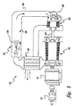
- FIG. 1 schematically illustrates a gas turbine system 10.
- typical gas turbines 10 are driven by the combustion gases from fuels, in that a flowing medium with a high energy content, i.e., the combustion gases, produces a rotary motion as a result of being deflected by rings of blading mounted on a rotor.
- the compressor 16 draws in fresh air and compresses it to a representative pressure on the order of about 3.515-5.272 kg/cm 2 (50-75 lb/in 2 ); the air is forced by the compressor 16 through a heat exchanger 32 where it is preheated by the heat that is still present in the exhaust combustion gases emerging from the turbine section 22; and finally, the preheated air is admitted into the combustion chamber of the combustion section 18.
- fuel is burned, thereby producing gases with a temperature of about 1500°C (2730°F). These combustion gases flow at a high velocity into turbine section 22 and drive it.
- the turbine 22 itself, the compressor 16 and the electric generator 14 are all mounted on a single shaft 24.
- the turbine cannot transmit its entire power output to the generator, for a substantial portion is needed for driving the compressor 16.
- the turbine section 22 is started with the aid of the electric motor 12 which first has to set the compressor in motion in order to produce compressed air and supply it to the combustion chamber so as to enable the combustion gases to be formed. Only then can the turbine start running.
- the combustion section 18, which includes the combustion chamber 36 provides for the flow of the combustion gas 28 from the combustion section 18 to the turbine inlet 30.
- a transition piece 38 connects the turbine inlet and the combustion section 18.
- These new methods include, for example, methods for making double-wall structures having integral internal channels such as assembling a double-wall assembly comprising an inner wall, a channel forming means, a sacrificial channel filling means and an outer wall, wherein the inner wall and the outer wall are complementary to one another and separated by the channel forming means that is placed between and in touching contact with them to define at least one channel, and wherein the sacrificial channel filling means is complementary to the channel forming means and placed into the channel forming means to fill the at least one channel, such that the double-wall assembly comprises a substantially solid structure; hot pressing the double-wall assembly at a temperature and for a time sufficient to cause the inner wall, outer wall and channel forming means to become metallurgically bonded to one another; and removing the sacrificial channel filling means.
- the outer wall material used in these methods could be selected from the group consisting of: stainless steel, Ni-base alloys, Co-base alloys, Fe-base alloys, Ti-base alloys, Cr-base or composite alloys, FeCrAIY-W alloys and Nb-base alloys.
- the inner wall material used in these methods could be selected from the group consisting of: stainless steel, Ni-base alloys, Co-base alloys, Fe-base alloys, Ti-base alloys, Cr-base or composite alloys, FeCrAIY-W alloys and Nb-base alloys.
- the channel forming means used in these methods could be selected from the group consisting of: stainless steels, Ni-base alloys, Co-base alloys, Fe-base alloys, Ti-base alloys and Nb-base alloys.
- the channel filling means used in these methods could be selected from the group consisting of: alloys comprising Ni and Cu, graphite, carbon steel, other carbonaceous materials, and including a glass or a salt that might be solid at the HlPing temp. and etched afterward.
- the hot pressing used in these methods includes hot isostatic pressing and specifically canning the double-wall assembly and evacuating the canned assembly prior to hot pressing.
- the hot pressing step could also include powder compaction.
- the channel filling means used in these methods could be accomplished by using a removal method selected from the group consisting of: chemical etching of the channel filling means, pyrolysis of the channel filling means, melting of the channel filling means and expulsion of the melt.
- the method of removing the channel filling means used in these methods could be accomplished by using a removal method selected from the group consisting of: dissolution of the channel filling means in a liquid not aggressive with respect to the wall channel materials.
- the at least one channel used in these methods has, in some applications, at least one stepwise offset for promoting turbulent fluid flow through the channel.
- the channel forming means used in these methods are a plurality of components that communicate with one another to form the at least one channel.
- One method used further comprises the step of creating a plurality of bores that extend through the inner wall into the at least one channel prior to the step of assembling the double-wall assembly, wherein the double-wall assembly also comprises a bore filling means that is inserted into the bore during the assembling step.
- One method used further comprises the step of creating a plurality of bores that extend through the inner wall into the at least one channel after hot pressing and prior to removing the channel filling means.
- One method further comprises the step of: creating a plurality of bores that extend through the inner wall into the at least one channel after said removing of the channel filling means.
- combustors and transition pieces fabricated with cooling channels between hot wall and cold wall surfaces have enhanced heat transfer to provide the necessary cooling.
- Such combustors and transition pieces can be fabricated according to the methods described in the examples below. Example 1 (Made but not tested).
- a first panel 92 Fig. 7, about 3.175 cm (1 1/4 inches) x about 8.9 cm (3 1/2 inches), was fabricated.
- the stainless steel channel geometry was similar to the examples below, and the sacrificial pieces were made from low carbon steel instead of monel, as with the examples below.
- the bottom wall 86 was made from a plate of stainless steel, as below.
- the top wall 88 was made using a powder foil approach. This method had been used to make foils from high-strength alloys.
- the original powder foil structure contained eighty (80) stainless steel 'U" channels 80 supported in HIPing by eighty (80) cold rolled steel blocks 82 (see Figure 7), separated by the sixteen (16) cold rolled steel grooved sections 84. These pieces were assembled on 0.05 cm (.02 inch) stainless foil, and HIP'ed with Ni alloy powder on the opposite face to make a 0.05 cm (0.02 inch) outer wall. After etching to remove the steel, the space between stainless and Ni alloy outer walls 86,88 consisted of vertical stainless partitions in the pattern shown in Figure 7.
- This first panel demonstrates the capability of the process to tailor the compositions of different sections to different thermal or mechanical requirements.
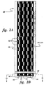
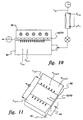
- An about16.36 cm ( 6.44 inch) x about 10.5 cm (4.14 inch) panel 52 with zig-zag cooling channels was HIP-fabricated from 304 stainless steel.
- the dimensions and internal structure of the panel after HIP are shown in Figure 4.
- the panel 52 consisted of stainless steel top 54 and bottom 56 plates, about 0.16 cm (1/16 inch) and about 0.475 cm (3/16 inch) thick, respectively.
- the stainless steel U-channels 58 had top walls about 0.1 cm (0.040 inches) thick and side walls about 0.2 cm (0.080 inches) thick.
- the channels were about 1.04 cm (0.410 inch) wide, and the side-to-side opening was about 0.635 cm (0.250 inches).
- the top-to-bottom opening 60 within the channels was about 10.41 cm (0.160 inches).
- the spacing between the channels was about 0.635 cm (0.250 inches), and the top-to-bottom dimension between the channels was about 0.51 cm (0.200 inches).
- the channels 58 were fitted tightly over sacrificial monel pieces (not shown), which were also zig-zagged in a manner similar to pieces 84 in example 1.
- the entire assembly was placed in a cold rolled steel HIP can, and evacuated.
- the can and the sacrificial monel pieces were removed by etching in a solution of about forty five percent (45%) nitric acid/about five percent (5%) suffuric acid/about fifty percent (50%) water.
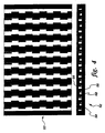
- a series of about 0.060 inch diameter holes (62 in Figure 5) for impingement cooling were then drilled through the bottom plate 56 of the stainless assembly. The holes did not touch the thin side, or the inner cooling channel walls.
- FIG. 5 An x-ray image of the drilled panel, Figure 5, illustrates the positions of the drilled holes 62 relative to the cooling channels and the walls. There are also holes that are not imaged in the 6 central channels that appear white in Figure 5.
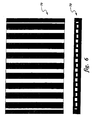
- a panel of the same size and wall thicknesses with straight through cooling channels Figure 6) was also fabricated using this technique, and then drilled with holes to produce the panel in Figure 8.
- impingement channels are comprised of coolant flow tubes or channels, whether straight or serpentined in some manner, which are fed by impingement jets through one wall.
- the objective of such channels is to take advantage of the high heat transfer performance associated with impingement, but in a manner which allows the directing of the flow according to cooling needs.
- a happy marriage of impingement and convective duct heat transfer would result which is superior to either impingement or duct heat transfer on their own.
- geometric configurations might be discerned which further enhanced convective heat transfer through the use of transverse roughness elements, jagged serpentines, or other means. The determination of an optimal configuration however, depends upon the many factors of impingement, those of convection, as well as those occurring through the interaction of the two.
- the baseline panel 70 shown in Figure 8 is formed of straight channels with regularly spaced impingement jets along the channel centerlines.
- the second panel 52 is a serpentine, called the zig-zag channel, as shown in Figure 9.
- the impingement jets have the same spacing and size, as in Figure 8, but are offset relative to the centerlines.
- Figures 10 and 11 show the test setup used for each unit. Moderate pressure air was supplied by a Worthington compressor at about 5.27 kg/cm 2 (75 psig) and about 21.11°C (70°F) to the flow venturl. The flow rate was determined from the in-line venturi measurements of inlet pressure, differential pressure, and temperature. Test section flow and pressure control was established with the use of three manual valves, a ball valve upstream of the venturi, a needle valve downstream of the venturi, and a ball valve downstream of the test section exit. Each panel 52, 70 has an array of 13 x 8 jets, that is, 8 jets equally spaced in each of the central 13 channels; the other channels do not flow in the tests.
- the panels 52, 70 were fitted with inlet 94 and exit 96 plenums in identical fashion, as in Figure 11.
- the inlet plenum 94 was large enough to ensure a uniform distribution of air to all impingement jets.
- the exit plenums 96 were flared out (expanded) from the channel exits to minimize non-uniform flow distribution due to back pressure. Temperature and static pressure were measured in the inlet plenum 94 and one exit plenum 96 (assuming symmetric flow to the two exits). Additional thermocouples were placed at each exit plenum 96 exit.
- the impingement surface (plate) of each test section had two thermocouples securely tacked into machined grooves.
- One thermocouple was intended to be located over a flow channel, while the other was over a separating rib.
- Heat input to the impingement surface was via a thick copper block, having five compact heating rods imbedded in it.
- the maximum heat rate of the unit was about 2100 watts (7170 btu/hr).
- the Cu block temperature was also monitored. Thermal contact between the Cu and the stainless steel test surface was facilitated by thermal grease and vise clamps. The entire assembly was wrapped with insulation.
- Table 1 shows the initial test matrix range planned for these units. For various jet Re, this table gives an indication of the associated impingement pressure ratios and pressure differentials involved.
- Initial Test Matrix for Channel Units The following matrix contains approximate numbers. The criteria used to establish these ranges were 1) maintaining an impingement pressure ratio P rat of 1.10 or less, and 2) keeping the jet Mach number in the incompressible range of M j less than or equal to 0.30. These criteria are to keep the tests within the representative range to unit the actual hardware. Inlet temperature of 530R has been assumed. The total mass flow rate through the unit is based on an array of 0.1524 cm (.060") diameter impingement holes of 13 x 8, assuming an average discharge coefficient of 0.8, using air as the fluid.
- Tables 3 and 4 present the test data for the baseline 70, and zig-zag 52 panels, respectively.
- the air outlet temperature is the average of the three exit thermocouples
- the wall average temperature is the average of the two metal surface thermocouples
- the DT f is the fluid temperature difference between inlet and average outlet
- the power is the total supplied to the heater.
- h ave is determined using the wall average-to-fluid average temperature potential (average of fluid inlet and exit).
- Baseline 70 Zig-Zag 52 Re h of Eq.(I) Watt/m 2 /K (btulhr/ft2/F) h ave h ave 22650 1487(262) 1816 (320) 1901 (335) 41700 2230 (393) 2451 (432) 2627 (463)
- impingement panel (52, 70) heat transfer performance is about 22-28% greater at the low Re and about 10-18% greater at the high Re, over the better plain impingement case of in-line jets.
- test cases represent only a start of the possible geometric configurations (fluid and structure). Optimization of the parameters may result in significantly greater heat transfer performance.
- a plate preform 40 about 3.81 cm(1 1/2 inch) x about 19.05 cm (7 1/2 inch) was made from an about 0.04 inch thick HA214 top 42 and bottom faces 44, about 0.013 cm (0.005 inch) thick 304 stainless steel foil separations 46, and an about 0.51 cm (0.2 inch) thick inner core comprised of 304 stainless steel U-channels 48 around sacrificial monel pieces 50.
- a cross-section of the plate 40 is shown in Figure 2.
- the channels and monel pieces ran continuously down the length of the plate.
- the channels were zig-zagged, a concept designed to enhance heat transfer of a structure by increasing turbulation.
- the plate was canned and then HlP'ed at about 1150°C/for about 4 hours/at about 15 ksi.
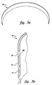
- the plate 40 was heated to about 950°C and then hot-rolled, for a total reduction of about seventy five percent (75%).
- An about 61 cm (twenty-four (24) inch) long section of the piece was then cold hoop-rolled to about 19.05 cm (7 1/2 inch) diameter.
- the ring was etched in a hot solution of about forty five percent (45%) nitric acid/about five percent (5%) sulfuric acid/ about fifty percent (50%) water, which removed the plain carbon steel HIP can as well as the sacrificial monel pieces 50 within the U-channels.
- the above described method could be used to fabricate structures, such as combustors and transition pieces for use in gas turbines and could possibly be made using different materials, such as a stronger alloy as the outer walls. If foils of high-strength superalloys are not available, the top and bottom faces of the preform could be made using in-process HIP consolidation of superalloy powders. Depending on the types of materials used, the structure could be ring-rolled hot, instead of cold.
- the above methods of making cylindrical structures with cooling channels could be used to make axial and/or circumferential cross-flow passages positioned between the structure's inner member and the outer member to provide cooling air thereto.
- the cooling channels are formed in the area between the inner member of the structure and the outer member thereof.
- the passages preferably extend axially and/or circumferentially with respect to the direction of flow through the structure.
- the axial passages extend completely from one end to the other and the circumferential passages extend around the circumference of the structure.
- the methods described herein can also be used to fabricate structures with internal features, serpentine passages of simple or high complexity, walls of variable thickness, accessibility to include flow inlets and exits where desired, and even 3D channels to follow the required structure dictated by aerodynamics.
- the examples show this technique can be applied to produce structures with enhanced cooling for application, such as for gas turbines, but the same approach could be used to fabricate reduced-weight components for aircraft engine applications, such as two-layer or multi-layer structures to replace solid components.
Landscapes
- Engineering & Computer Science (AREA)
- Mechanical Engineering (AREA)
- Manufacturing & Machinery (AREA)
- Chemical & Material Sciences (AREA)
- Combustion & Propulsion (AREA)
- General Engineering & Computer Science (AREA)
- Turbine Rotor Nozzle Sealing (AREA)
- Pressure Welding/Diffusion-Bonding (AREA)
- Powder Metallurgy (AREA)
Applications Claiming Priority (2)
| Application Number | Priority Date | Filing Date | Title |
|---|---|---|---|
| US669069 | 1996-06-24 | ||
| US08/669,069 US5822853A (en) | 1996-06-24 | 1996-06-24 | Method for making cylindrical structures with cooling channels |
Publications (3)
| Publication Number | Publication Date |
|---|---|
| EP0815995A2 EP0815995A2 (en) | 1998-01-07 |
| EP0815995A3 EP0815995A3 (en) | 1998-12-23 |
| EP0815995B1 true EP0815995B1 (en) | 2002-06-05 |
Family
ID=24684876
Family Applications (1)
| Application Number | Title | Priority Date | Filing Date |
|---|---|---|---|
| EP97304420A Expired - Lifetime EP0815995B1 (en) | 1996-06-24 | 1997-06-24 | Method for making cylindrical structures with cooling channels |
Country Status (4)
| Country | Link |
|---|---|
| US (1) | US5822853A (enExample) |
| EP (1) | EP0815995B1 (enExample) |
| JP (1) | JP4052363B2 (enExample) |
| DE (1) | DE69712983T2 (enExample) |
Cited By (1)
| Publication number | Priority date | Publication date | Assignee | Title |
|---|---|---|---|---|
| US9296072B2 (en) | 2010-10-05 | 2016-03-29 | Snecma | Method for manufacturing a metal part |
Families Citing this family (41)
| Publication number | Priority date | Publication date | Assignee | Title |
|---|---|---|---|---|
| SE512942C2 (sv) * | 1998-10-02 | 2000-06-12 | Volvo Aero Corp | Förfarande för tillverkning av utloppsmunstycken för raketmotorer |
| CA2288557C (en) * | 1998-11-12 | 2007-02-06 | Mitsubishi Heavy Industries, Ltd. | Gas turbine combustor cooling structure |
| US6402470B1 (en) | 1999-10-05 | 2002-06-11 | United Technologies Corporation | Method and apparatus for cooling a wall within a gas turbine engine |
| US6254334B1 (en) | 1999-10-05 | 2001-07-03 | United Technologies Corporation | Method and apparatus for cooling a wall within a gas turbine engine |
| US6655234B2 (en) | 2000-01-31 | 2003-12-02 | Baker Hughes Incorporated | Method of manufacturing PDC cutter with chambers or passages |
| EP1146289B1 (en) * | 2000-04-13 | 2008-12-24 | Mitsubishi Heavy Industries, Ltd. | Cooling structure of combustor tail tube |
| US6408610B1 (en) * | 2000-07-18 | 2002-06-25 | General Electric Company | Method of adjusting gas turbine component cooling air flow |
| FR2812828B1 (fr) * | 2000-08-10 | 2003-03-14 | Atmostat Etudes Et Rech S | Procede de fabrication de dispositif d'echange thermique et dispositif d'echange thermique obtenu par ce procede |
| US6878412B2 (en) * | 2001-03-26 | 2005-04-12 | Bodycote Imt, Inc. | Corrosion resistant component and method for fabricating same |
| US6530225B1 (en) | 2001-09-21 | 2003-03-11 | Honeywell International, Inc. | Waffle cooling |
| US6722134B2 (en) | 2002-09-18 | 2004-04-20 | General Electric Company | Linear surface concavity enhancement |
| US6761031B2 (en) | 2002-09-18 | 2004-07-13 | General Electric Company | Double wall combustor liner segment with enhanced cooling |
| US7104067B2 (en) * | 2002-10-24 | 2006-09-12 | General Electric Company | Combustor liner with inverted turbulators |
| US6681578B1 (en) | 2002-11-22 | 2004-01-27 | General Electric Company | Combustor liner with ring turbulators and related method |
| FR2850741B1 (fr) * | 2003-01-30 | 2005-09-23 | Snecma Propulsion Solide | Procede de fabrication d'un panneau de refroidissement actif en materiau composite thermostructural |
| US7186084B2 (en) * | 2003-11-19 | 2007-03-06 | General Electric Company | Hot gas path component with mesh and dimpled cooling |
| US6984102B2 (en) * | 2003-11-19 | 2006-01-10 | General Electric Company | Hot gas path component with mesh and turbulated cooling |
| US7216485B2 (en) * | 2004-09-03 | 2007-05-15 | General Electric Company | Adjusting airflow in turbine component by depositing overlay metallic coating |
| US7464554B2 (en) * | 2004-09-09 | 2008-12-16 | United Technologies Corporation | Gas turbine combustor heat shield panel or exhaust panel including a cooling device |
| US7243700B2 (en) * | 2005-10-27 | 2007-07-17 | United Technologies Corporation | Method for casting core removal |
| US7493965B1 (en) | 2006-04-12 | 2009-02-24 | Us Synthetic Corporation | Apparatuses and methods relating to cooling a subterranean drill bit and/or at least one cutting element during use |
| DE102007022310A1 (de) * | 2007-05-12 | 2008-11-13 | Arno Friedrichs | Verfahren zur Herstellung eines Kühlkanäle aufweisenden Kreissägeblattes |
| US8376706B2 (en) * | 2007-09-28 | 2013-02-19 | General Electric Company | Turbine airfoil concave cooling passage using dual-swirl flow mechanism and method |
| GB0722850D0 (en) * | 2007-11-22 | 2008-01-02 | Advanced Interactive Materials | Net or near net shape powder metallurgy process |
| JP4768763B2 (ja) * | 2008-02-07 | 2011-09-07 | 川崎重工業株式会社 | 二重壁冷却型のガスタービン燃焼器の冷却構造 |
| GB0805250D0 (en) * | 2008-03-20 | 2008-04-30 | Advanced Interactive Materials | Stator for use in helicoidal motor |
| GB0805242D0 (en) * | 2008-03-20 | 2008-04-30 | Advanced Interactive Materials | Net-shape or near net-shape powder isostatic pressing process |
| US20100011770A1 (en) * | 2008-07-21 | 2010-01-21 | Ronald James Chila | Gas Turbine Premixer with Cratered Fuel Injection Sites |
| US8727706B2 (en) | 2011-01-04 | 2014-05-20 | General Electric Company | System for providing cooling and purging air flow to a rotary machine online monitoring system |
| US9950382B2 (en) * | 2012-03-23 | 2018-04-24 | Pratt & Whitney Canada Corp. | Method for a fabricated heat shield with rails and studs mounted on the cold side of a combustor heat shield |
| US20140216043A1 (en) * | 2013-02-06 | 2014-08-07 | Weidong Cai | Combustor liner for a can-annular gas turbine engine and a method for constructing such a liner |
| US10520193B2 (en) * | 2015-10-28 | 2019-12-31 | General Electric Company | Cooling patch for hot gas path components |
| US11199105B2 (en) | 2017-07-26 | 2021-12-14 | General Electric Company | Monitoring system for a gas turbine engine |
| US11371702B2 (en) | 2020-08-31 | 2022-06-28 | General Electric Company | Impingement panel for a turbomachine |
| US11460191B2 (en) | 2020-08-31 | 2022-10-04 | General Electric Company | Cooling insert for a turbomachine |
| US11614233B2 (en) | 2020-08-31 | 2023-03-28 | General Electric Company | Impingement panel support structure and method of manufacture |
| US11994292B2 (en) | 2020-08-31 | 2024-05-28 | General Electric Company | Impingement cooling apparatus for turbomachine |
| US11994293B2 (en) | 2020-08-31 | 2024-05-28 | General Electric Company | Impingement cooling apparatus support structure and method of manufacture |
| US11255545B1 (en) | 2020-10-26 | 2022-02-22 | General Electric Company | Integrated combustion nozzle having a unified head end |
| GB2620549A (en) * | 2022-06-27 | 2024-01-17 | The Manufacturing Tech Centre Limited | A method for creating an object |
| US11767766B1 (en) | 2022-07-29 | 2023-09-26 | General Electric Company | Turbomachine airfoil having impingement cooling passages |
Family Cites Families (13)
| Publication number | Priority date | Publication date | Assignee | Title |
|---|---|---|---|---|
| FR2012723A1 (enExample) * | 1968-07-11 | 1970-03-20 | Messerschmitt Boelkow Blohm | |
| JPS58217605A (ja) * | 1982-06-08 | 1983-12-17 | Natl Aerospace Lab | ロケツト燃焼器製作法 |
| DE3436419C2 (de) * | 1983-10-07 | 1990-11-15 | Yoshimichi Chigasaki Kanagawa Masuda | Verfahren zur Herstellung von Raketenbrennkammern |
| JPS6082603A (ja) * | 1983-10-07 | 1985-05-10 | Natl Aerospace Lab | ロケツト燃焼器製作法 |
| US4956201A (en) * | 1988-06-29 | 1990-09-11 | The United States Of America As Represented By The Secretary Of The Air Force | Method of creating pasageways in niobium by CVD of niobium over sintered vanadium which is thereafter leached |
| JP3142850B2 (ja) * | 1989-03-13 | 2001-03-07 | 株式会社東芝 | タービンの冷却翼および複合発電プラント |
| US5075966A (en) * | 1990-09-04 | 1991-12-31 | General Electric Company | Method for fabricating a hollow component for a rocket engine |
| US5249357A (en) * | 1993-01-27 | 1993-10-05 | The United States Of America As Represented By The Administrator Of The National Aeronautics And Space Administration | Method of fabricating a rocket engine combustion chamber |
| US5328331A (en) * | 1993-06-28 | 1994-07-12 | General Electric Company | Turbine airfoil with double shell outer wall |
| US5427736A (en) * | 1994-04-05 | 1995-06-27 | General Electric Company | Method of making metal alloy foils |
| US5480468A (en) * | 1994-06-27 | 1996-01-02 | General Electric Company | Ni-base alloy foils |
| US5613299A (en) * | 1994-11-09 | 1997-03-25 | Ring; Peter J. | Method of fabricating a rocket thrust chamber |
| US5724816A (en) * | 1996-04-10 | 1998-03-10 | General Electric Company | Combustor for a gas turbine with cooling structure |
-
1996
- 1996-06-24 US US08/669,069 patent/US5822853A/en not_active Expired - Lifetime
-
1997
- 1997-06-24 EP EP97304420A patent/EP0815995B1/en not_active Expired - Lifetime
- 1997-06-24 DE DE69712983T patent/DE69712983T2/de not_active Expired - Fee Related
- 1997-06-24 JP JP16692797A patent/JP4052363B2/ja not_active Expired - Fee Related
Cited By (1)
| Publication number | Priority date | Publication date | Assignee | Title |
|---|---|---|---|---|
| US9296072B2 (en) | 2010-10-05 | 2016-03-29 | Snecma | Method for manufacturing a metal part |
Also Published As
| Publication number | Publication date |
|---|---|
| US5822853A (en) | 1998-10-20 |
| DE69712983D1 (de) | 2002-07-11 |
| EP0815995A2 (en) | 1998-01-07 |
| JPH10115425A (ja) | 1998-05-06 |
| DE69712983T2 (de) | 2003-01-23 |
| JP4052363B2 (ja) | 2008-02-27 |
| EP0815995A3 (en) | 1998-12-23 |
Similar Documents
| Publication | Publication Date | Title |
|---|---|---|
| EP0815995B1 (en) | Method for making cylindrical structures with cooling channels | |
| US5933699A (en) | Method of making double-walled turbine components from pre-consolidated assemblies | |
| US9200855B2 (en) | Tubular heat exchange systems | |
| EP3073217B1 (en) | Heat exchanger for a gas turbine engine | |
| US9410702B2 (en) | Gas turbine engine combustors with effusion and impingement cooling and methods for manufacturing the same using additive manufacturing techniques | |
| US9764435B2 (en) | Counter-flow heat exchange systems | |
| EP1400750B1 (en) | Double wall connector segment for a gas turbine with cooling channels having concavities | |
| EP3071913B1 (en) | Monolithic tube-in matrix heat exchanger | |
| EP2759772B1 (en) | Combustors with complex shaped effusion holes | |
| JP4150938B2 (ja) | ガスタービン用高温ガス制御構造 | |
| JP2693665B2 (ja) | ガスタービン燃焼器ライナ、アフタバーナ用ガスタービンエンジン排気部燃焼器ライナ及びガスタービン燃焼器ライナを製造する方法 | |
| JP2016020693A (ja) | 付加製造された表面仕上げ | |
| US10260749B2 (en) | Combustion chamber wall and a method of manufacturing a combustion chamber wall | |
| US11906249B2 (en) | Tube bank heat exchanger | |
| JP2000145479A (ja) | ガスタービン燃焼器の冷却構造 | |
| EP3961101B1 (en) | Integrated combustor nozzle | |
| EP3961102A1 (en) | Impingement panel and method of manufacture | |
| EP4394254B1 (en) | Integrated combustor nozzle with impingement panel and method of manufacture | |
| EP3961100B1 (en) | Integrated combustor nozzle for a turbomachine |
Legal Events
| Date | Code | Title | Description |
|---|---|---|---|
| PUAI | Public reference made under article 153(3) epc to a published international application that has entered the european phase |
Free format text: ORIGINAL CODE: 0009012 |
|
| AK | Designated contracting states |
Kind code of ref document: A2 Designated state(s): CH DE FR GB LI |
|
| PUAL | Search report despatched |
Free format text: ORIGINAL CODE: 0009013 |
|
| AK | Designated contracting states |
Kind code of ref document: A3 Designated state(s): AT BE CH DE DK ES FI FR GB GR IE IT LI LU MC NL PT SE |
|
| 17P | Request for examination filed |
Effective date: 19990623 |
|
| AKX | Designation fees paid |
Free format text: CH DE FR GB LI |
|
| 17Q | First examination report despatched |
Effective date: 19991006 |
|
| GRAG | Despatch of communication of intention to grant |
Free format text: ORIGINAL CODE: EPIDOS AGRA |
|
| GRAG | Despatch of communication of intention to grant |
Free format text: ORIGINAL CODE: EPIDOS AGRA |
|
| GRAH | Despatch of communication of intention to grant a patent |
Free format text: ORIGINAL CODE: EPIDOS IGRA |
|
| GRAH | Despatch of communication of intention to grant a patent |
Free format text: ORIGINAL CODE: EPIDOS IGRA |
|
| GRAA | (expected) grant |
Free format text: ORIGINAL CODE: 0009210 |
|
| AK | Designated contracting states |
Kind code of ref document: B1 Designated state(s): CH DE FR GB LI |
|
| REG | Reference to a national code |
Ref country code: GB Ref legal event code: FG4D |
|
| REG | Reference to a national code |
Ref country code: CH Ref legal event code: EP |
|
| REG | Reference to a national code |
Ref country code: CH Ref legal event code: NV Representative=s name: SERVOPATENT GMBH |
|
| REF | Corresponds to: |
Ref document number: 69712983 Country of ref document: DE Date of ref document: 20020711 |
|
| ET | Fr: translation filed | ||
| PLBE | No opposition filed within time limit |
Free format text: ORIGINAL CODE: 0009261 |
|
| STAA | Information on the status of an ep patent application or granted ep patent |
Free format text: STATUS: NO OPPOSITION FILED WITHIN TIME LIMIT |
|
| 26N | No opposition filed |
Effective date: 20030306 |
|
| REG | Reference to a national code |
Ref country code: CH Ref legal event code: PFA Owner name: GENERAL ELECTRIC COMPANY Free format text: GENERAL ELECTRIC COMPANY#1 RIVER ROAD#SCHENECTADY, NY 12345 (US) -TRANSFER TO- GENERAL ELECTRIC COMPANY#1 RIVER ROAD#SCHENECTADY, NY 12345 (US) |
|
| PGFP | Annual fee paid to national office [announced via postgrant information from national office to epo] |
Ref country code: CH Payment date: 20080630 Year of fee payment: 12 |
|
| PGFP | Annual fee paid to national office [announced via postgrant information from national office to epo] |
Ref country code: FR Payment date: 20080617 Year of fee payment: 12 |
|
| PGFP | Annual fee paid to national office [announced via postgrant information from national office to epo] |
Ref country code: GB Payment date: 20080627 Year of fee payment: 12 |
|
| PGFP | Annual fee paid to national office [announced via postgrant information from national office to epo] |
Ref country code: DE Payment date: 20080930 Year of fee payment: 12 |
|
| REG | Reference to a national code |
Ref country code: CH Ref legal event code: PL |
|
| GBPC | Gb: european patent ceased through non-payment of renewal fee |
Effective date: 20090624 |
|
| REG | Reference to a national code |
Ref country code: FR Ref legal event code: ST Effective date: 20100226 |
|
| PG25 | Lapsed in a contracting state [announced via postgrant information from national office to epo] |
Ref country code: LI Free format text: LAPSE BECAUSE OF NON-PAYMENT OF DUE FEES Effective date: 20090630 Ref country code: FR Free format text: LAPSE BECAUSE OF NON-PAYMENT OF DUE FEES Effective date: 20090630 Ref country code: CH Free format text: LAPSE BECAUSE OF NON-PAYMENT OF DUE FEES Effective date: 20090630 |
|
| PG25 | Lapsed in a contracting state [announced via postgrant information from national office to epo] |
Ref country code: GB Free format text: LAPSE BECAUSE OF NON-PAYMENT OF DUE FEES Effective date: 20090624 |
|
| PG25 | Lapsed in a contracting state [announced via postgrant information from national office to epo] |
Ref country code: DE Free format text: LAPSE BECAUSE OF NON-PAYMENT OF DUE FEES Effective date: 20100101 |