EP0814705B1 - Appareil de soulevement flexible - Google Patents
Appareil de soulevement flexible Download PDFInfo
- Publication number
- EP0814705B1 EP0814705B1 EP96907919A EP96907919A EP0814705B1 EP 0814705 B1 EP0814705 B1 EP 0814705B1 EP 96907919 A EP96907919 A EP 96907919A EP 96907919 A EP96907919 A EP 96907919A EP 0814705 B1 EP0814705 B1 EP 0814705B1
- Authority
- EP
- European Patent Office
- Prior art keywords
- body wall
- engaging element
- lifting
- wall engaging
- flexible
- Prior art date
- Legal status (The legal status is an assumption and is not a legal conclusion. Google has not performed a legal analysis and makes no representation as to the accuracy of the status listed.)
- Expired - Lifetime
Links
Images


Classifications
-
- A—HUMAN NECESSITIES
- A61—MEDICAL OR VETERINARY SCIENCE; HYGIENE
- A61B—DIAGNOSIS; SURGERY; IDENTIFICATION
- A61B17/00—Surgical instruments, devices or methods, e.g. tourniquets
- A61B17/02—Surgical instruments, devices or methods, e.g. tourniquets for holding wounds open; Tractors
- A61B17/0281—Abdominal wall lifters
-
- A—HUMAN NECESSITIES
- A61—MEDICAL OR VETERINARY SCIENCE; HYGIENE
- A61B—DIAGNOSIS; SURGERY; IDENTIFICATION
- A61B17/00—Surgical instruments, devices or methods, e.g. tourniquets
- A61B17/02—Surgical instruments, devices or methods, e.g. tourniquets for holding wounds open; Tractors
- A61B17/0218—Surgical instruments, devices or methods, e.g. tourniquets for holding wounds open; Tractors for minimally invasive surgery
-
- A—HUMAN NECESSITIES
- A61—MEDICAL OR VETERINARY SCIENCE; HYGIENE
- A61B—DIAGNOSIS; SURGERY; IDENTIFICATION
- A61B17/00—Surgical instruments, devices or methods, e.g. tourniquets
- A61B2017/00535—Surgical instruments, devices or methods, e.g. tourniquets pneumatically or hydraulically operated
- A61B2017/00557—Surgical instruments, devices or methods, e.g. tourniquets pneumatically or hydraulically operated inflatable
-
- A—HUMAN NECESSITIES
- A61—MEDICAL OR VETERINARY SCIENCE; HYGIENE
- A61B—DIAGNOSIS; SURGERY; IDENTIFICATION
- A61B50/00—Containers, covers, furniture or holders specially adapted for surgical or diagnostic appliances or instruments, e.g. sterile covers
- A61B50/30—Containers specially adapted for packaging, protecting, dispensing, collecting or disposing of surgical or diagnostic appliances or instruments
- A61B2050/314—Flexible bags or pouches
Definitions
- the present invention concerns an apparatus for deployment through a laparoscopic incision in a body wall according to the precharacterizing portion of claim 1 (WO-A-92 21291).
- the invention generally relates to an apparatus for lifting a body wall during surgery, especially during laparoscopic surgery.
- a well-known method of raising the abdominal wall is to insufflate the abdominal cavity with a suitable insufflation gas, such as air, or carbon dioxide.
- a suitable insufflation gas such as air, or carbon dioxide.
- gas insufflation is that elongated instruments must be passed into the abdominal cavity through gas-tight seals, which significantly reduce the surgeon's feel of the instruments.
- the Californiayerli Endoscopic Retractor Model 1 described in SURGICAL LAPAROSCOPY AND ENDOSCOPY, Vol. 1, No. 2, 1991, pages 98-100, has a rigid rod with a hinged blade at the distal end.
- the blade can rotate through 360 degrees about an axis perpendicular to the long axis of the rod.
- the blade is aligned with the long axis of the rod for insertion into the abdomen through a small puncture. Once inside the abdomen, the blade is swivelled through about 90 degrees to form a T-shaped structure.
- the proximal end of the rod can be raised by hand or by a rope, pulley and weight arrangement. Raising the rod causes the blade to engage the abdominal wall and to lift it.
- French patent application no. 90-03980 shows a wire structure that is threaded into the abdomen through a small puncture to engage and to lift the abdominal wall.
- the application also shows a fan retractor that has a first angle-shaped member having a first leg that engages with the abdominal wall, a tubular second leg having a bore, and a third leg, remote from the first leg, that has a hook-shaped member on its end distal from the second leg.
- a second angle-shaped member has a first leg that engages with the abdominal wall, a second leg that pivots within the bore of the second leg of the first angle-shaped member, and a third leg, remote from the first leg, that serves as an operating lever for the second angle-shaped member.
- the first legs of the angle-shaped members are closed together to insert them into the abdominal cavity through an incision.
- the third leg of the second angle-shaped member is then operated to spread the first leg of the second angle-shaped member apart from the first leg of the first angle-shaped member.
- the first legs are engaged with the peritoneum inside the abdominal cavity.
- a lifting force is then applied to the hook-shaped member to lift the retractor and hence to lift the abdominal wall.
- United States Patent Application Serial No. 08/062,707 (US-A-5 501 653), assigned to the assignee of this application, describes a number of different mechanical devices that are inserted through one or more punctures into the abdomen. All or part of the device is then lifted to lift the abdominal wall away from the underlying abdominal organs.
- One of the devices described in this application is a fan retractor that is inserted in a closed condition into the abdominal cavity, spread apart once inside the abdominal cavity, and brought into contact with the peritoneum insidle the abdominal cavity. The apparatus is then lifted to lift the abdominal wall.
- the above-mentioned fan retractors can be used with intra-abdominal placement. Because the peritoneum-engaging elements of such devices are relatively elongated, it is possible to snag the bowel or omentum during deployment. Under some circumstances, it may be necessary to make multiple attempts at inserting the retractor before the fan retractor can be correctly positioned with its peritoneum-engaging elements adjacent to the peritoneum with no bowel or omentum caught between the peritoneum-engaging elements and the peritoneum. Insufflating the abdomen before inserting the fan retractor does not necessarily eliminate the risk of snagging.
- United States patent application serial no. 07/890,033 (US-A-5 501 653, assigned to the assignee of this application, describes a fan retractor that can be inserted into the abdomen properitoneally to prevent snagging.
- the abdominal wall contacting legs of the fan retractor are shaped to enable them to dissect the peritoneum away from the abdominal wall so that the peritoneum can act as a drape over the underlying organs.
- the legs are shaped to provide a stiffness that decreases away from the pivot to enable the legs to conform to the internal shape of the abdominal wall.
- the known mechanical lifting devices described above generally expose a smaller area of the underlying organs than conventional gas insufflation. Moreover, the known mechanical lifting devices are inserted into the abdomen through a laparoscopic incision. Consequently, due to the dimensional constraints imposed by the need to pass though such a small incision, these devices apply the lifting force to a relatively small area of the abdominal wall, and, consequently, expose the small area of the abdominal wall to a relatively high lifting pressure.
- United States patent application serial no. 08/239,348 (WO-A-9 530 375), assigned to the assignee of this application and published after the date of priority of this application, hereinafter the "prior application,” describes an inflatable lifting apparatus that has a flat lifting surface.
- the inflatable lifting apparatus is intended for deployment through a laparoscopic incision in a body wall to apply an external lifting force over a large area of the body wall.
- the apparatus has a body wall engaging element and an elongate lifting tube.
- the body wall engaging element is shaped to pass in a packaged state through the laparoscopic incision in the body wall.
- the body wall engaging element is inflatable to an inflated state, and includes, in the inflated state, a plane lifting surface.
- the lifting tube includes a distal portion that is connected to the lifting surface of the body wall engaging element, and is also shaped to pass through the laparoscopic incision.
- the lifting tube also includes a proximal portion that receives the external lifting force in a direction that moves the body wall engaging element into contact with the body wall.
- the inflatable lifting apparatus described in the prior application overcomes many of the disadvantages of the purely mechanical lifting devices.
- the elongate lifting tube is hollow, and provides access to the body cavity for a surgical instrument.
- a rigid lifting tube limits lateral and angular movement of an instrument inserted therein.
- instrument ports are provided in the body wall engaging element.
- using these instrument ports requires that additional laparoscopic incisions be made in the body wall.
- movement of a instrument inserted through an instrument port is still partially constrained, because the lifting tube can obstruct movement of the instrument.
- the body wall engaging element of the inflatable apparatus described in the prior application is preferably constructed from a relatively thin material to make the body wall engaging extremely compact in its collapsed state.
- the thin material may limit the maximum inflation pressure that can be reliably used.
- the body wall engaging element has a complex internal structure of baffles to enable it to assert the required lifting force against the body wall when inflated to a relatively low inflation pressure.
- the baffles increase the bulk of the body wall engaging element in its collapsed state, and make the body wall engaging element complex to manufacture.
- the collapsed body wall engaging element of the inflatable lifting apparatus described in the prior application may require a considerable tractive force applied to the lifting tube to remove it from the body cavity through the laparoscopic incision.
- the present invention provides a lifting apparatus that fulfills two main performance requirements that conflict with one another.
- the lifting apparatus includes a broad lifting surface that is capable of applying a lifting force of at least (180 Newtons) 40 pounds to an area of a body wall that is sufficiently extensive that the lifting pressure exerted on the body wall is well below that which could cause pressure trauma to the body wall.
- the lifting apparatus delivers this broad lifting surface into the body cavity underlying the body wall through an incision in the body wall about 14 mm long.
- the present invention additionally provides a lifting apparatus that retains the advantages of the inflating lifting apparatus described in the prior application, and which has additional operational advantages. These advantages include an improved access for surgical instruments without the need for additional incisions, and a greater freedom of movement for surgical instruments, including allowing surgical instruments to be inserted at an oblique angle.
- the lifting apparatus according to the present invention additionally allows the patient to move or be moved relative to the lifting arm, and enables the body wall to be disposed at different angles relative to the direction of lift.
- the lifting apparatus according to the present invention provides an improved ease of manufacture.
- the invention provides an apparatus for deployment through a laparoscopic incision in a body wall to apply an external lifting force over a large area of the body wall.
- the apparatus comprises a body wall engaging element capable of passing in a packaged state through the laparoscopic incision, and being inflatable to an inflated state. In the inflated state, the body wall engaging element is substantially toroidal, provides a broad lifting face, and bounds a central hole.
- the body wall engaging element includes an equatorial portion facing into the central hole.
- the apparatus also includes a flexible lifting element that has a flexible portion capable of passing through the laparoscopic incision. The flexible portion is attached to the equatorial portion of the body wall engaging element and extends from the equatorial portion towards the broad lifting face.
- the flexible lifting element also includes an adapter, connected to part of the flexible portion remote from the equatorial portion of the body wall engaging element, that receives the external lifting force and transfers the external lifting force to the flexible portion.
- a lifting apparatus comprising a flat, substantially circular or elliptical body wall engaging element having a center, an outer periphery, and opposed faces, and having a flexible lifting element attached to approximately the center and extending from one of the faces.
- An elongate pouch is also provided having an open end and having on one side a central aperture and on the other side a longitudinal line of perforations.
- the body wall engaging element is rolled from diametrically opposed points on the outer periphery towards the center. After rolling, the body wall engaging element is substantially cylindrical.
- the flexible lifting element is threaded into the open end of the pouch and out of the central aperture of the pouch. Finally, the rolled body wall engaging element is inserted into the pouch, which retains it in its rolled state.
- a lifting apparatus in the method, includes a body wall engaging element in a packaged state, capable of passing through the laparoscopic incision.
- the body wall engaging element is inflatable from the packaged state to an inflated state in which the body wall engaging element is substantially toroidal, provides a broad lifting face, and bounds a central hole.
- the lifting apparatus also includes a flexible lifting element that has a flexible portion capable of passing through the laparoscopic incision and an adapter.
- the flexible portion is attached to the equatorial portion of the body wall engaging element and extends from the equatorial portion towards the broad lifting face.
- the adapter is connected to part of the flexible portion remote from the equatorial portion of the body wall engaging element, receives the external lifting force, and transfers the external lifting force to the flexible portion.
- the packaged body wall engaging element and part of the flexible lifting element are advanced through the laparoscopic incision.
- the body wall engaging element is inflated to an inflated state to provide a broad lifting surface.
- the external lifting force is applied to the adapter of the flexible lifting element to move the broad lifting surface into contact with the body wall and to lift the body wall from a normal state to a lifted state.
- the preferred embodiment of the lifting apparatus 10 according to the invention is shown in its operational state in Figures 1A-1F, in which perspective, top, bottom, cross sectional, and elevational views are respectively shown.
- the lifting apparatus 10 has two main components, the body wall engaging element 12 and the flexible lifting element 14, as shown in the perspective view of Figure 1A. Additional details of the components of the lifting apparatus 10 are shown in Figures 3, 4A, 4B, and 5.
- the lifting apparatus 10 is also shown in its packaged state, prior to insertion into the body cavity in Figures 2A-2C.
- the envelope 18 of the body wall engaging element 12 is tightly rolled, as shown in the cross-sectional view of Figure 2B and in the enlarged cross-sectional view of Figure 2C, and is retained in this state by the pouch 22 to form the package 24.
- the flexible lifting element 14 extends from the aperture 29 mid-way along the side of the package 24, and the inflation tube 26 and the tether 28 extend from the proximal end 30 of the package, as will be described in more detail below.
- the body wall engaging element 12 will pass easily through a laparoscopic incision in the body wall into the underlying body cavity, for example, into the abdominal cavity.
- the laparoscopic incision should be as small as possible. Consequently, it is desirable that the cross-sectional area of the package 24 be minimized because the cross-sectional area of the package determines the size of the incision.
- the package 24 containing a body wall engaging element 12 capable of exerting a lifting force of at least (180 N) 40 pounds can be inserted through a laparoscopic incision about 14 mm long.
- the flexible lifting element 14 is attached to a suitable lifting arm (not shown).
- the lifting arm applies the lifting force to the flexible lifting element 14.
- the flexible lifting element 14 transmits the lifting force to the body wall engaging element 12.
- the body wall engaging element transfers the lifting force to the body wall (not shown) via the broad, flat lifting surface 16 and lifts the body wall.
- the large area of the lifting surface 16 of the body wall engaging element 12 distributes the lifting force substantially uniformly over a large area of the body wall.
- the lifting apparatus according to the invention applies a considerably lower lifting pressure to the body wall than its applied by the mechanical lifting devices described above.
- the body wall engaging element 12 In its inflated state, the body wall engaging element 12 is toroidal and has a substantially elliptical cross section.
- the toroidal body wall engaging element bounds the central hole 32. Instruments and endoscopes can be passed though the incision and the central hole 32 to perform surgical procedures in the working space created by the lifting apparatus 10 lifting the body wall. If the flexible lifting element 14 obstructs movement of an instrument, the flexible lifting element is flexible, so can easily be moved out of the way.
- the lifting force is removed, which returns the body wall to its normal (non-lifted) state.
- the flexible lifting element 14 is released from the lifting arm, the inflation fluid is released from the body wall engaging element 12, and the body wall engaging element is evacuated to minimize its volume.
- the proximal end of the tether 28, which remains outside the body cavity during the treatment procedure, is gently pulled axially to align part of the perimeter of the envelope 18 with the laparoscopic incision. Further gentle tension on the tether 28 withdraws the envelope from the body cavity through the incision. In the course of withdrawing the envelope through the incision, the part of the flexible lifting element 14 that was inside the body cavity is also withdrawn. Once the lifting apparatus has been withdrawn from the incision, the incision is closed in the normal way.
- the body wall engaging element 12 is substantially toroidal.
- the toroid has a substantially elliptical cross section.
- the minor axis of the ellipse is aligned with the lifting direction and is preferably about one half of the length of the major axis.
- This shape provides the body wall engaging element with the broad lifting surface 16 while affording access through the central hole 32 to the working space created by lifting the body wall.
- the central hole is located relative to the flexible lifting element 14 such that, when the body wall is lifted, the central hole is aligned with the incision through which the flexible lifting element 14 passes through the body wall (and through which the body wall engaging element 12 was inserted into the body cavity underlying the body wall). This alignment enables instruments inserted into the incision to reach the working space underlying the body wall engaging element via the central hole 32.
- the lifting surface 16 is more curved than that of the body wall engaging element of the inflating lifting apparatus described in the prior application. However, this curvature does not significantly increase the lifting pressure applied to the body wall by the lifting surface 16 relative to that applied by a flat lifting surface. This is because inflatable body wall engaging elements have an intrinsic limitation on the lifting pressure applied to the body wall, namely, the inflation pressure. The body wall engaging element 12 deforms in response to the lifting force until the area of the lifting surface 16 in contact with the body wall increases to that required to transfer all the lifting force to the body wall.
- the inflation pressure used in the lifting apparatus according to the invention although larger than that used in the apparatus with the flat lifting surface described above, is well below that at which the lifting pressure applied to the body wall could cause pressure trauma to the body wall.
- the body wall engaging element 12 lacks the internal baffles of the body wall engaging element of the inflating lifting apparatus described in the prior application, and is therefore considerably simpler, consisting of the upper envelope half 34 and the lower envelope half 36 forming the envelope 18.
- the stiffness required for the body wall engaging element 12 to transfer the lifting force to the body wall is provided by using a considerably increased inflation pressure.
- the envelope halves 34 and 36 use a new composite material that has the strength and resistance to leakage required to provide reliability in spite of the increase in inflation pressure.
- the new envelope material is thicker than the envelope material used in the flat-surface lifting apparatus, but since the body wall engaging element 12 lacks internal baffles, it uses fewer square cm (square inches) of envelope material, and the bulk of the package 24 is little different from that of the package of the flat-surface lifting apparatus. Eliminating the internal baffles not only makes the lifting apparatus according to the invention easier to manufacture, it also increases potential reliability, because the number of welded joints, each of which may fail, is substantially reduced.
- the composite material of the envelope halves 34 and 36 is required to have a combination of strength, flexibility, suppleness, low bulk, weldability, and resistance to leakage.
- Polyamide such as nylon, has the necessary strength requirements but is almost impossible to weld.
- Polyamide fiber has tensile strength advantages over polyamide film at the expense of greater thickness.
- Polyurethane has the required flexibility and weldability requirements, but has poor strength characteristics.
- a composite of these materials provides the advantages of both materials.
- Initial embodiments were made from a composite material formed by laminating an open-weave fabric made of 200 denier monofilament nylon with about (8-12 threads/cm) 20-30 threads/inch between two layers of polyurethane film about 4 mil. (100 ⁇ m) thick using heat and pressure.
- This composite material had excellent strength characteristics and the bulk material had very low leakage.
- the relative stiffness of the nylon monofilaments led to leakage problems when the material was welded. Welding released the monofilaments from the polyurethane matrix, and the voids left in the polyurethane matrix provided a leakage path for the inflation fluid. Leakage was reduced by substituting 200 denier spun nylon thread for the nylon monofilaments in the fabric.
- a further improvement in strength characteristics was obtained by using a more closely woven fabric of 200 denier spun nylon thread with (24 ⁇ 18 threads/cm) 60 ⁇ 45 threads per inch .
- the fabric was heat and pressure laminated between two (100 ⁇ m) 4 mil. layers of polyurethane to form an envelope material that was nominally (300 ⁇ m) 14 mil. thick.
- the upper envelope half 34 and the lower envelope half 36 are annular and are welded together at their inner peripheries 44 and at their outer peripheries 45 to form a toroidal chamber. Because of the threads in the composite envelope material form a square matrix, the body wall engaging element 12 tends to assume a square shape when inflated. This shape may be optimum in some applications.
- the body wall engaging element 12 can be made round for applications that require this shape by orienting the threads of the upper envelope half 34 at about 45 degrees to the threads of the lower envelope half 36 prior to welding the envelope halves together.
- the directions in which the threads run in the upper envelope half 34 and in the lower envelope half 36 are respectively shown by the area 20 in the top view of Figure 1B and the area 21 in the bottom view of Figure 1C.
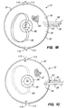
- the upper envelope half 34 may be welded to the lower envelope half 36 as shown in Figures 3A and 3B.
- parts that are identical to those shown in Figures 1A-1F are indicated by the same reference numeral, and parts that are similar are indicated by the same reference numeral with the letter "A" added.
- the way of welding the envelope halves together shown in Figures 3A and 3B is simplest because both the inner seam 38 and the outer seam 40 can be welded in one operation.
- the outer seam 40 projects outwards from the body wall engaging element 12A and, when the body wall engaging element is inflated, is relatively rigid.
- the nylon fibres in the envelope material give the outer seam a rough outer edge 41. Additional processing, such as flame treatment, or welding a thin cover over the outer edge, must therefore be performed to provide the outer seam with a smooth outer edge.
- the outer seam 42 is contained by the body wall engaging element 12, and the envelope 18 isolates the outer seam 42 from the patient. Consequently, no additional processing is required to provide a smooth outer edge to the outer seam.
- the outer seam 42 is formed inside the body wall engaging element 12 by a two-step welding process in which the upper envelope half 34 is welded to the lower envelope half 36 at the outer seam 42 first, and the resulting structure is turned inside out before the upper envelope half 34 is welded to the lower envelope half 36 at the inside seam 38.
- Locating the outer seam 42 inside the body wall engaging element 12 imposes an additional requirement on the envelope material.
- the exposed ends of the threads of the nylon fabric inside the body wall engaging element 12 are exposed to the inflation fluid at the inflation pressure, whereas the ends of these threads adjacent the inner seam 38 are exposed to the ambient pressure of the body cavity.
- the threads are porous, and the pressure differential between the ends of the threads causes inflation fluid to leak from the body wall engaging element along the length of the threads.
- the nylon fabric is made non-porous by saturating it with polyurethane prior to laminating it between the polyurethane films.
- a small section 43 of the outer seam 42 in the body wall engaging element 12 shown in Figures 1A-1F, and a small section of the outer seam 40 in the body wall engaging element 12A shown in Figures 3A and 3B is left unwelded to provide a gap into which the inflation tube 26 is inserted, as will be described in detail below.
- the body wall engaging element 12 is adapted for receiving the lifting force at its equator 46 by increasing the width of the inner seam 38 beyond that which is required to reliably join the upper envelope half 34 to the lower envelope half 36.
- the extended-width inner seam provides the lifting flange 48.
- the lifting flange is about (6 mm) 0.25" wide.
- the flexible lifting element 14 is composed of the flexible element 50 and the arm attachment element 52.
- the arm attachment element is configured for attachment to a table-mounted standard lifting arm, such as the LaparoliftTM sold by the assignee of the present invention, and for transferring the lifting force exerted by the lifting arm to the flexible element 50.
- the flexible element transfers the lifting force from the arm attachment element 52 to the body wall engaging element 12, to which the flexible element is attached.
- the flexible element 50 has a number of practical advantages over the rigid lifting tube of the inflating lifting apparatus described in the prior application.
- the flexible element reduces the bulk of the lifting apparatus in the form in which it is inserted into and removed from the body cavity.
- the flexible element minimally obstructs the movement of instruments inserted into the incision. If the surgeon desires to move an instrument to a position where it would be obstructed by the flexible element, he/she can simply move the flexible element out of the way.
- the flexible element allows the patient to move or be moved laterally relative to the lifting arm.
- the flexible element enables the body wall engaging element 12 to be operated at different angles relative to the direction of the lifting force exerted by the lifting arm.
- the flexible element 50 must transfer a lifting force of up to (180 N) 40 pounds to the lifting flange 48 on the equator 46 of the body wall engaging element 12 in a manner that minimizes localized stress.
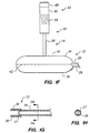
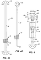
- the preferred embodiment of the flexible element 50 called the epsilon 54, is shown in Figure 4A.
- the epsilon 54 distributes the lifting force substantially uniformly over the entire area of the lifting flange.
- the epsilon 54 is cut from a single piece of composite material and consists of two semi-annular portions 56 integral with, and interconnected by, the strap 58.
- the semi-annular portions are dimensioned such that they collectively cover substantially the entire area of the lifting flange 48, as shown in Figure 1B.
- the epsilon 54 is preferably cut from a single piece of composite material using laser cutting or ultrasonic cutting. Both of these methods result in a clean edge that is protected from fraying by melting of the composite material during the cutting process.
- the fabric is formed from 840 denier spun nylon thread with 32 x 30 threads per 25 mm (inch). The fabric is treated with an anti-fraying resin, and is then laminated between two (125 ⁇ m) 5 mil. thick polyurethane films, to provide a material with a total nominal thickness of (600 ⁇ m) 24 mil..
- the thread orientation in the epsilon 54 is shown by the area 55 in Figure 4A.
- the nylon fabric in the composite material of the epsilon 54 is tightly woven to maximize the efficiency by which the lifting force applied to the strap 58 is distributed uniformly across the surface of the semi-annular portions 56.
- the lifting force is applied in the strap 58 to the relatively few warp threads 57 that run along the length of the strap from one of the annular portions 56 to the other.
- these warp threads transfer the lifting force to the relatively few weft threads 59 that are woven with them.
- These weft threads in turn distribute the lifting force to the threads covering the remainder of the area of the semi-annular portions.
- the strap 58 is preferably made as long as possible to make the part of the strap attached to each of the semi-annular portions 56 as close to parallel as possible during lifting. This reduces the lateral component of the lifting force applied to opposite sides of the central hole 32 and the tendency of this lateral component to close the central hole.
- the length of the strap is limited in practice to about (330 mm) 13" by the maximum upwards excursion of the lifting arm.
- the strap is about (6 mm) 0.25" wide.
- the semi-annular portions 56 are RF welded to the entire lifting flange area of the lower envelope half 36, preferably before the lower envelope half is welded to the upper envelope half 34.
- the lifting flange area of the lower envelope half is the part of the lower envelope half that will constitute the lifting flange 48 when the lower envelope half is welded to the upper envelope half 34.
- the semi-annular portions are welded over their entire area, so that, in the finished body wall engaging element, the lifting force is distributed over the entire area of the lifting flange 48, thereby minimizing localized stress.
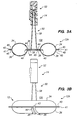
- the arm attachment element 52 is shown in detail in Figure 5, and has three main components, the housing 60, the strap hanger 62, and the dovetail connector 64.
- the dovetail connector 64 is preferably molded integrally with the housing 60, and mates with a complementary dovetail connector (not shown) mounted on the lifting arm.
- the housing and the strap hanger are preferably moldings of a suitable plastic, for example, polycarbonate.
- the dovetail connector 64 when mated with a complementary dovetail connector, transmits the lifting force unidirectionally, i.e., upwards. Also, because the dovetail connector 64 is off-center relative to the housing 60, it also transmits a torque to the complementary dovetail connector. If the lifting arm is lowered to a point at which the lifting force would be applied to the housing in a downwards direction, the dovetail connector automatically disengages from the complementary dovetail connector. This prevents the downwards force being transmitted via the housing to the patient. With the lifting apparatus according to the present invention, the flexible element 50 provides the main mechanism for minimizing the possibility of a downwards force being transmitted to the patient, and the dovetail connector 64 simply provides a backup.
- the strap hanger 62 includes the cylindrical portion 66 extending axially from the center of the knob 68.
- the cylindrical portion is swivellingly received in the bore 70 of the housing 60.
- Rotating the knob 68 changes the rotational position of the strap 58 when the housing is attached to the table-mounted lifting arm.
- the upper rim 72 of the housing 60 transmits the lifting force to the lower face 74 of the knob 68 of the strap hanger 62.
- the cylindrical portion of the strap hanger 62 is formed with the groove 76 that engages with the flange 78 molded in the bore 70 of the housing to locate the strap hanger axially.
- the cylindrical portion 66 of the strap hanger includes the axial bore 84, and the transverse bore 86 through the wall of the axial bore.
- the strap 58 is attached to the arm attachment element by forming the strap into a loop, inserting the loop into the axial bore 84 and inserting the pin 88 into the transverse bore 86 and the loop.
- the inflation tube 26 is preferably a piece of polyurethane tube with an outside diameter of about (4 mm) 0.16" and a wall thickness of about (1 mm) 40 mil., about (380 mm) 15" long.
- the inflation tube is glued into the gap 43 between the envelope halves 34 and 36 left unwelded when the outer seam 42 was welded.
- a UV-cured cyano-acrylate adhesive is preferably used.
- the anti-kinking device 27 is formed from a piece of 50-pound test monofilament about (100 mm) four inches long. The piece of monofilament is bent in half along its length and is inserted into the inflation tube close to where the inflation tube is connected to the envelope halves 34 and 36. Anti-kinking measures can be applied over a greater extend to the inflation tube 26 if necessary. Alternatively, kink-resistant tubing can be used for the inflation tube 26.
- the inflation tube 26 is fitted at its end remote from the body wall engaging element 12 with the one-way valve 80.
- the valve 80 includes the portion 82 to which the bulb inflator 163 can be attached to inflate or evacuate the body wall engaging element.
- the valve 80 is a one-way valve and also preferably has a pressure-limiting characteristic.
- the pressure limiting characteristic of the valve 80 prevents the inflation pressure of the body wall engaging element from rising above a predetermined limit pressure.
- the limit pressure of the valve 80 is chosen to be greater than the minimum pressure required to provide the body wall engaging element 12 with the stiffness it requires to enable it to transfer the lifting force to the body wall, but well below the pressure at which the integrity of the body wall engaging element is impaired.
- the limit pressure is chosen to be 70 kPa (10 psi)
- the pressure limiting characteristic of the valve 80 enables the surgeon to inflate the body wall engaging element without having to monitor the inflation pressure and without having to be concerned about over-inflating the body wall engaging element.
- the surgeon simply operates the bulb inflator 163 until he/she hears air being released by the valve 80, which indicates that the pressure in the body wall engaging element has reached the operating pressure. If the procedure is lengthy, the bulb inflator can be operated occasionally to replace inflation fluid lost due to minor leakage. The bulb inflator is again operated until the valve 80 is heard to release.
- the valve 80 can alternatively and preferably simply have a one-way characteristic, and the bulb inflator 163 can be fitted with the pressure-limiting valve 164.
- the pressure limiting valve 164 fitted to the bulb inflator limits the inflation pressure of the body wall engaging element similarly to the valve 80 with a pressure limiting characteristic.
- References hereinafter to the valve 80 having a pressure limiting characteristic will be understood to include a valve with a pressure limiting characteristic included into the bulb inflator.
- the tether 28 shown in Figure 4B provides a reliable means for withdrawing the collapsed body wall engaging element 12 from the body cavity at the end of the procedure.
- the distal end 90 of the tether is attached to one of the envelope halves, preferably the lower envelope half 36, close to the outer seam 42 at or close to the point on the periphery of the envelope half to which the inflation tube 26 will later be attached.
- the tether Prior to attaching the end of the tether 28 to the envelope half, the tether is oriented so that it extends radially outwards from the center of the envelope half.
- the tether is preferably attached to the lower envelope half by RF welding before the lower envelope half is welded to the upper envelope half 34.
- the tether 28 is cut from a piece of the same type of composite material as the epsilon 54.
- the warp threads of the fabric core of the composite material are oriented along the length of the tether, as shown by the area 93 in Figure 4B.
- tether 28 extends from the proximal end of the package. After the body wall engaging element has been inserted into the body cavity, the proximal end 92 of the tether remains outside the body cavity. At the end of the procedure, following deflation and evacuation of the body wall engaging element 12 to a collapsed state, the proximal end 92 of the tether is pulled proximally to withdraw the collapsed body wall engaging element edge-first from the body cavity through the incision.
- the inflation tube 26 may be pulled proximally to assist the tether 28 in withdrawing the collapsed body wall engaging element from the body cavity, but it is impractical to use the inflation tube as a substitute for the tether.
- the inflation tube itself is too elastic, and the strength of the glued joint between the inflation tube and the envelope 18 is insufficient for the inflation tube to serve as a reliable substitute for the tether.
- the lifting apparatus 10 is shown in its packaged state, prior to insertion into the body cavity in Figure 2A.
- a cross-sectional view of the packaged body wall engaging element 12 is shown in Figure 2B, and an enlarged cross-sectional view of the packaged body wall engaging element 12 is shown in Figure 2C.
- the body wall engaging element 12 is packaged in a manner that minimizes the cross-sectional area of the package 24. This minimizes the size of the incision required for the body wall engaging element to be inserted into the body cavity, and, hence, minimizes trauma to the patient.
- the body wall engaging element 12 is also packaged in a manner that enables the body wall engaging element to be released from its packaging simply by inflating the body wall engaging element, and that enables withdrawal of the body wall engaging element from the body cavity automatically to withdraw the packaging.
- the body wall engaging element 12 is maintained in its packaged state by the pouch 22.
- the pouch is made by attaching the upper pouch half 94 to the lower pouch half 96 along their peripheries at their sides 98 and distal end 105. This leaves the proximal end 101 open.
- the upper and lower pouch halves are preferably attached to one another by RF welding.
- the upper and lower pouch halves are cut from a thin film of a weldable plastic, such as (80 ⁇ m) 2 mil. polyurethane.
- the length of the pouch halves is about (25 mm) one inch greater than the diameter of the upper and lower envelope halves 34 and 36.
- the upper pouch half 94 bounds the aperture 29 through which the flexible element 50 exits the pouch 24.
- the lower pouch half 96 includes the line of perforations 103 formed along part of its center line, preferably in the same operation in which the lower pouch half is cut from the film of weldable plastic.
- the line of perforations 103 extends proximally along the length of the lower pouch half from the distal end 105 to the terminator 107, which is spaced about (12 mm) 1 ⁇ 2" from the open proximal end 101.
- the terminator 107 is a small circular aperture about (240 microns) 60 mil. in diameter, and serves to define the proximal end of the line of perforations. The function of the terminator 107 will be described in more detail below.
- the body wall engaging element 12 is first evacuated to prevent air trapped inside the body wall engaging element from increasing the bulk of the package. Evacuation reduces the body wall engaging element 12 to a substantially flat disc.
- the flexible lifting element 14 is arranged to extend from the upper envelope half 34 side of the body wall engaging element, i.e., to extend from the side of the body wall engaging element from which will extend in use.
- the inflation tube 26 and the tether 28 are arranged to extend radially from the body wall engaging element 12.
- Opposite ends 113 of the diameter of the envelope 18 perpendicular to the direction of the inflation tube 26 and the tether 28 are then rolled in the direction shown by the arrows 115 in Figure 1C. This direction is opposite to that from which the flexible lifting element 14 extends from the body wall engaging element 12. This rolls the opposite ends 113 of the diameter of the envelope18 inwards towards the central hole 32. Rolling is continued until the two rolled portions of the envelope contact one another, as shown in Figures 2B and 2C. As the rolled portions of the envelope approach the center of the body wall engaging element, the semi-annular portions 56 of the epsilon 54 are also subject to rolling.
- the body wall engaging element 12 is substantially cylindrical, and has the inflation tube 26 and the tether 28 extending from its proximal end, and has the flexible lifting element 14 extending from its center.
- the body wall engaging element: 12 is held in its rolled state, and the arm attachment element 52 of the flexible lifting element 14 is threaded through the pouch 22, entering at the open proximal end 101 and leaving through the aperture 29, drawing the strap 58 behind it.
- This orients the rolled body wall. engaging element relative to the pouch so that the rolled portions of the envelope face towards the line of perforations 103 in the lower pouch half 96.
- the distal end of the rolled body wall engaging element 12, remote from the inflation tube 26, is then inserted into the pouch 22 through the open end 101.
- the arm attachment element 52 is pulled axially to withdraw the strap 58 from the pouch.
- Insertion is continued until the distal end of the rolled body wall engaging element reaches the distal end 105 of the pouch.
- the arm attachment element 52 is then manipulated to lay the strap 58 along the length of the package 24, and to bring the arm attachment element close to the inflation tube 26 and the tether 28 emerging from the open end 101 of the pouch 22, as shown in Figure 2A.
- An enlarged cross sectional view of the rolled body wall engaging element 12 inside the pouch 22 is shown in Figure 2C.
- the inflation tube 26 and the tether 28 may temporarily be attached to the arm attachment element 52 following manufacture and prior to use.
- Rolling the body wall engaging element 12 and inserting the body wall engaging element into the pouch 22 with the lifting element emerging from the aperture 29, and with the rolled portion facing the line of perforations 103 enables the pouch to reliably retain the rolled body wall engaging element in its rolled state during storage and insertion of the body wall engaging element into the body cavity, and yet enables inflation of the body wall engaging element to release the body wall engaging element from the pouch.
- Initial inflation of the rolled body wall engaging element 12 causes the rolled body wall engaging element to unroll slightly. This applies a lateral stress to the lower pouch half 96, which causes the lower pouch half to split along the line of perforations 103.
- the lower pouch half splitting releases the pouch from around the rolled body wall engaging element, and allows the body wall engaging element to expand unimpeded by the pouch.
- the terminator 107 at the proximal end of the line of perforations 103 reduces the tendency for the lower pouch half to tear beyond the end of the line of perforations when the body wall engaging element 12 is inflated.
- the part 111 of the pouch encircling the inflation tube 26 and the tether 28 remains intact and keeps the pouch connected to the body wall engaging element following release of the body wall engaging element from the pouch 22.
- the pouch is additionally connected to the body wall engaging element by the strap 58 passing through the aperture 29 in the pouch.
- FIGS 6A-6C Parts of an alternative embodiment 110 of the lifting apparatus according to the invention are shown in Figures 6A-6C.
- elements that are the same as those shown in Figures 1A-1F are indicated by the same reference numerals, and elements that are similar to those shown in Figures 1A-1F are indicated by the same reference numerals with 100 added.
- the part of the envelope 118 of the body wall engaging element 112 that forms the lifting flange 148 is pierced with the punctures 119.
- the punctures are located at substantially constant angular intervals and are inset from the inner perimeter of the lifting flange.
- the embodiment shown in Figures 6A-6C has a different flexible lifting element from the embodiment shown in Figures 1A-1F.
- the flexible lifting element 114 shown in Figures 6A-6C includes the upper ring 121, the lower ring 123, and the suspension 125.
- the lifting flange 148 of the body wall engaging element 112 is sandwiched between the upper ring 121 and the lower ring 123.
- the upper ring and lower ring are similar to one another and are circular with a rectangular or square cross section.
- the upper ring and lower ring are preferably moldings of a rigid plastic such as a polyetherimid.
- the upper ring 121 and the lower ring 123 are formed with the holes 127 (one of twelve holes is indicated by the reference numeral 127 in Figure 6A) corresponding to the punctures 119 in the lifting flange 148. Because the upper ring and the lower ring are rigid, they define a minimum cross-sectional dimension for the packaged apparatus.
- the outside diameter of the upper and lower rings is about (19 mm) 0.75" .
- the inner diameter of the upper and lower rings defines the central hole 132, and is about (12 mm) 0.5". This is smaller than the 25 mm (1 inch) diameter of the central hole 32 of the embodiment shown in Figures 1A-1F.
- the upper ring 121A and the lower ring 123A can be elliptical instead of circular.
- the upper ring and the lower ring are preferably aligned with their major axes in the direction of the inflation tube 26 and the tether 28. This aligns the minor axes of the rings perpendicular to the longitudinal axis of rolled body wall engaging element, and provides the central hole with an increased area compared with circular upper and lower rings without increasing the cross-sectional area of the body wall engaging element 112 in its packaged state.
- the monofilament 129 and the sleeves 131 form the suspension 125.
- the monofilament 129 is a length of 50-pound test nylon monofilament about (0.5 mm) 20 mil. in diameter, and the sleeves are each a length of polyurethane or PVC tubing with an internal diameter of 40 mil. (1 mm), an outside diameter of (2 mm) 80 mil., and a length of over twice that of the strap 58.
- the sleeves serve as a cushion between the monofilament 129 and the incision, and prevent the monofilament from enlarging the incision.
- the monofilament 129 is sequentially threaded through the holes 127 in the upper and lower rings 121 and 123 and the corresponding punctures 119 in the lifting flange 148, and is threaded twice through each sleeve 131, as shown in Figures 6A-6C. Finally, the free ends of the monofilament 129 emerge in the same direction from two adjacent ones of the holes 127 in the lower ring 123 and are connected together as indicated by the reference numeral 135. This attaches the upper ring 121 and the lower ring 123 to opposite sides of the lifting flange 148, and forms the suspension 125.
- the suspension 125 is connected in the arm attachment element 52 (omitted from the drawings for clarity) by forming the portions 133 of the monofilament 129 remote from the upper ring 141 into a loop, inserting the loop into the axial bore 84 of the strap hanger 62 and inserting the pin 88 into the transverse bore 86 and the loop in a manner similar to that shown in Figure 5.
- the upper ring 121 can be attached to the lower ring 123 and the lifting flange 148 by riveting through all but two pairs of diametrically-opposite ones of the holes 127.
- the monofilament 129 can then be threaded through each of the non-riveted holes and the sleeves 131 to form the suspension 125.
- FIG. 7A-7C Part of another alternative embodiment 210 of the lifting apparatus according to the invention is shown in Figures 7A-7C.
- elements that are the same as those shown in Figures 1A-1F are indicated by the same reference numerals, and elements that are similar to those shown in Figures 1A-1F are indicated by the same reference numerals with 200 added.
- the part of the envelope 218 (only a part of the envelope is shown) of the body wall engaging element that forms the lifting flange 248 is pierced with the two pairs of diametrically-opposite punctures 219. The punctures are inset from the inner perimeter 249 of the lifting flange 248.
- the embodiment shown in Figures 7A-7C has a different flexible lifting element from the embodiments shown in Figures 1A-1F and in Figures 6A-6C.
- the flexible lifting element 214 shown in Figures 7A-7C includes the ring 241 and the suspension 225.
- the ring 241 is circular with a rectangular cross section and is cut from a nylon fabric/polyurethane composite material similar to the envelope material, but of considerably greater thickness (about (0.1") 2.5 mm).
- the ring 241 is formed with the diametrically-opposed pairs of holes 227 corresponding to diametrically-opposed punctures 219 in the lifting flange 248.
- the ring 241 is attached to the portion of the lower envelope half 236 forming the lifting flange 248, preferably by RF welding, with the holes 227 aligned with the punctures 219.
- the outside diameter of the ring 241 is about (25 mm) one inch, and its inside diameter, which defines the central hole 232, is about (12 mm) 0.5" . This is smaller than the 25mm (one-inch) diameter of the central hole 32 of the embodiment shown in Figures 1A-1F.
- a piece of very high-strength nylon string 229 enclosed by the sleeve 231 provides the suspension 225.
- the nylon string is looped through the pairs of diametrically-opposed holes 227 and threaded twice through the sleeve 231, as shown in Figures 7B and 7C, and its free ends are connected together.
- the sleeve 231 retains any fibres shed from the nylon string 229.
- nylon monofilament or stainless-steel wire string may be used, in which case the sleeve prevents the monofilament or the wire from enlarging the incision.
- the suspension 225 is connected in the arm attachment element 52 (omitted from the drawings for clarity) by forming the portions 233 of the string 229 remote from the ring 241 into a loop, inserting the loop into the axial bore 84 of the strap hanger 62 and inserting the pin 88 into the transverse bore 86 and the loop in a manner similar to that shown in Figure 5.
- FIG. 8A-8C Part of another alternative embodiment 310 of the lifting apparatus according to the invention is shown in Figures 8A-8C.
- elements that are the same as those shown in Figures 1A-1F are indicated by the same reference numerals, and elements that are similar to those shown in Figures 1A-1F are indicated by the same reference numerals with 300 added.
- the body wall engaging element is the same as that shown in Figures 1A-1F, but the flexible lifting element 314 is different from that of the embodiments shown in Figures 1A-1F, Figures 6A-6C, and Figures 7A-7C is used.
- the flexible lifting element 314 shown in Figures 8A-8C includes the transfer segments 341 and 343 and the suspension 325.
- the ring 241 is cut from a piece of fabric-reinforced composite material.
- the ring made this way has an unfinished inside edge 243 ( Figures 7A and 7B) that has a relatively low resistance to lateral tearing.
- the ring must be made strong enough to prevent the lifting force from causing the nylon string to tear the ring from the holes 227 to the inside edge 243. Consequently, the suspension 225 in the embodiment shown in Figures 7A-7C is formed by looping the nylon string 229 through two holes on each side of the ring 241 to reduce the lateral pressure between the nylon string and the holes 227. The reduced lateral pressure reduces the ability of the nylon string to tear the ring 241.
- the ring 241 is also formed using a thick (2.5 mm) composite material to reduce its resistance to tearing.
- the transfer segments 341 and 343 are short lengths of a ribbon of a nylon fabric/polyurethane composite material similar to the envelope material.
- the thickness of this material is about 1.2 mm, which is considerably greater than that of the envelope material, but less than the composite material used to form the ring 241 in the embodiment shown in Figures 7A-7C.
- the ribbon is woven with selvedges, indicated by the broken lines 345, along its length.
- a selvedge is about twenty times more resistant to lateral tearing than the unfinished inside edge 243 of the ring 241 in the Figures 7A-7C embodiment.
- Each transfer segment is cut from the ribbon with the portions 347 and 349 shaped to match the outer perimeter of the lifting flange.
- the transfer segments are about 15 mm wide and 40 mm long.
- Each of the transfer segments 341 and 342 is formed with the hole 327.
- the hole is formed in a portion of the transfer segment that does not overlap the lifting flange 348. No punctures need therefore be formed in the lifting flange
- the transfer segments 341 and 343 are attached to the part of the lower envelope half 336 forming the lifting flange, preferably by RF welding. Prior to welding, the transfer segments are aligned so that their longitudinal axes are parallel to the direction of the lifting tube 26 ( Figures 1A-1F). Thus, when the body wall engaging element is packaged, the transfer segments are rolled across their short dimensions.
- a piece of very high-strength nylon string 329 enclosed by the sleeve 331 provides the suspension 325.
- the nylon string is threaded through one of the diametrically-opposed holes 327, through the sleeves 331, and the other of the diametrically-opposed holes 327.
- the ends of the nylon string are then respectively inserted into the flanged fittings 351 and 352, where they are retained by crimping the flanged fittings.
- the flanged fittings couple the lifting force to the transfer segments 341 and 343.
- the flanged fittings may be dispensed with, and the ends of the nylon string 339 may simply be knotted.
- a metal or plastic washer may be put on each end of the nylon string prior to knotting the ends of the string to distribute the lifting force over a wider area of the transfer segments.
- the flanged fittings also distribute the lifting force over a relatively large area of the transfer segments.
- the suspension 325 is connected in the arm attachment element 52 (omitted from the drawings for clarity) by forming the portion 333 of the string 329 remote from the transfer segments 341 and 343 into a loop, inserting the loop into the axial bore 84 of the strap hanger 62 and inserting the pin 88 into the transverse bore 86 and the loop in a manner similar to that shown in Figure 5.
- the sleeve retains any fibres shed from the nylon string 329.
- nylon monofilament or stainless-steel wire string may be used, in which case the sleeve prevents the monofilament or the wire string from the enlarging the incision.
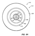
- FIG. 9A and 9B An alternative embodiment 412 of the body wall engaging element suitable for use with any of the flexible lifting elements 14, 114, 214, and 314 shown in Figures 1A-1F, 6A-6C, 7A-7C and 8A-8C is shown in Figures 9A and 9B.
- the embodiment of the body wall engaging element 412 shown in Figures 9A and 9B uses the flexible lifting element 14 shown in Figures 1A-1F as an example.
- the body wall engaging element 412 is based on the baffled body wall engaging element described in the prior application, but is adapted for connection to the flexible lifting element 14.
- Figures 9A and 9B respectively show a bottom view and a cross-sectional view of the lifting apparatus 410 incorporating the alternative body wall engaging element 412 with the body wall engaging element in its inflated state.
- the body wall engaging element 412 Prior to insertion into the body cavity, the body wall engaging element 412 is evacuated and packaged in a manner similar to that described above with reference to Figures 2A-2C. Accordingly, packaging the body wall engaging element 412 will not be described again here.
- the body wall engaging element 412 In its inflated state, the body wall engaging element 412 has the large, flat, lifting surface 416 by means of which it transfers the lifting force to the body wall. Despite the large area of the lifting surface, the height of the body wall engaging element in the axial direction is relatively small, typically in the range of 12-25 mm, which minimizes the intrusion of the inflated body wall engaging element into the working space created by lifting the body wall.
- the body wall engaging element 412 is substantially toroidal and bounds the central hole 32 that provides access to the tissues underlying the lifted body wall through the body wall engaging element.
- the large area of the lifting surface 416 of the body wall engaging element 412 enables a large area of the body wall to be lifted and distributes the lifting force applied to the flexible lifting element 414 uniformly over this large area.
- the maximum lifting pressure applied to the body wall is not significantly greater than that applied by convention gas insufflation.
- the body wall engaging element 412 is formed from an upper envelope half 434 and a lower envelope half 436 which are joined together at their outer peripheries 445 and are interconnected at their inner peripheries 444 and at several intermediate points by the baffles 437.
- the inner-most baffle 465 bounds the central hole and is formed to include the lifting flange 448 to which the flexible lifting element 414 is attached.
- the semi-annular portions 56 of the epsilon 54 are welded to the underside of the lifting flange 448, and the strap 58 of the epsilon is connected to the arm attachment element 52 by the pin 88, as described above with reference to Figure 5.
- the upper envelope half 434 and the lower envelope half 436 form the envelope 418 of the body wall contacting element 412.
- the envelope halves are annular and are shaped to define the shape of the body wall engaging element and to define the extent of the central hole 432.
- the upper and lower envelope halves are substantially circular.
- the envelope halves are attached to one another at their outer peripheries 445, preferably by RF welding.
- the baffles 437 interconnect the upper and lower envelope halves 434 and 436.
- the baffles provide the body wall engaging element 412 with its plane lifting surface 16 when the body wall engaging element is inflated. Without the baffles, the lifting surface would be convex, as in the embodiments shown in Figures 1A-1F.
- the inner-most baffle 467 connects the inner peripheries 444 of the upper and lower envelope halves and also provides the part of the body wall engaging element 412 that bounds the central hole 432.
- the inner-most baffle 467 is formed in the same manner as the other baffles 437, as will be described in detail below. However, the upper and lower baffle halves constituting the inner-most baffle 467 are attached to one another over an extended area to form the lifting flange 448. The semi-annular portions 56 of the epsilon 54 are then attached to the part of the lower baffle half constituting the lifting flange. RF welding is the preferred way of attaching the upper and lower baffle halves to one another and to the semi-annular portions of the epsilon.
- the position of the outer-most baffle 439 relative to the outer periphery 445 of the envelope halves is chosen to provide the body wall engaging element 412 with the rounded shoulder 447.
- the rounded shoulder helps the body wall engaging element conform to the shape assumed by the abdominal wall at the transition between the portion of the abdominal wall that supported by the inflating lifting apparatus and the portion that is not supported. This prevents the lifting pressure applied to the abdominal wall increasing at the periphery of the body wall engaging element.
- the baffles 437 provide the body wall engaging element with much of the stiffness by which the body wall engaging element uniformly transfers the lifting force from the flexible lifting element 414 to the large area of the body wall.
- the baffles are preferably attached to the envelope halves by RF welding, as will be described below.
- the baffles 437 are arranged so that they run parallel to the outer periphery 445 of the body wall engaging element 412. This divides the body wall engaging element into a number of communicating concentric chambers.
- the holes 465 are formed in the baffles. In some applications, some of the baffles may be arranged radially.
- the body wall engaging element 412 must be capable of withstanding inflation pressures sufficiently high to provide it with the stiffness necessary to transfer the lifting force uniformly from the flexible lifting element 414 to the body wall.
- inflation pressures sufficiently high to provide it with the stiffness necessary to transfer the lifting force uniformly from the flexible lifting element 414 to the body wall.
- to minimize the bulk of the body wall engaging element in its packaged state, and, hence, to minimize the size of incision required, as thin a material as possible should be used for the envelope halves 434 and 436 and the baffles 437.
- the material of the envelope halves and the baffles must have good welding characteristics.
- the envelope halves and the baffles are preferably made of a composite film made by laminating a material with good welding characteristics, such as urethane, with a strong material, such as polyester.
- a material with good welding characteristics such as urethane
- a strong material such as polyester.
- An alternative composite material is a composite film made by extruding a material with good welding characteristics, such as polyethylene, with a strong material, such as nylon.
- a nylon or polyester fabric layer (12-50 ⁇ m) 0.5 to 2 mil. thick is used as the core of the envelope material.
- the nylon or polyester fabric layer can be a woven fabric or can be a layer of randomly-oriented fibres.
- the nylon or polyester fabric layer is laminated between two polyurethane films to provide a film of envelope material with a preferred thickness of about (75 ⁇ m) 3 mil.. The polyurethane films bond securely to the uneven surface of the nylon or polyester fabric layer.
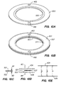
- the baffles 437 are preferably fabricated and attached to the upper envelope half 434 and the lower envelope half 436 by the process shown in Figures 10A through 10E. This process assembles the baffles and attaches them to the upper and lower envelope halves using two welding operations.
- the two-piece baffle used in the procedure saves having to bend the baffles prior to welding, as would be required if one-piece baffles were used.
- the assembly of the circular body wall engaging element 412 shown in Figures 1A-1D will be described.
- Each baffle is made from the annular upper baffle half 501 and the annular lower baffle half 503.
- One of the baffle halves, for example, the lower baffle half 503 is selectively coated with a suitable welding release agent in the shaded area 505 shown in Figure 10A.
- the upper baffle half 501 is then laid on top of the lower baffle half 503, as shown in Figure 10B, and the pair of baffle halves is placed between the first pair of circular RF welding electrodes W 1 and W 2 , as shown in the cross-sectional view of Figure 10C.
- the first welding electrodes W 1 and W 2 then weld the two baffle halves together along their outer peripheries, as indicated by the phantom line 507 shown in Figure10B, to form the baffle 437.
- the completed baffle 437 is then laid on the lower envelope half 436 between the circular second welding electrodes W 3 and W 4 , as shown in the cross-sectional view of Figure 10D.
- the second welding electrodes have a smaller diameter than that of the first welding electrodes W 1 and W 2 .
- the upper envelope half 434 is then laid over the completed baffle and the lower envelope half.
- the second welding electrodes W 3 and W 4 then perform a second welding operation to weld the baffle 437 along the inner periphery the baffle to the upper envelope half and the lower envelope half.
- the second welding operation welds the upper baffle half 501 to the upper envelope half 434 along the phantom line 511, remote from the phantom line 507, shown in Figure 10B.
- the second welding operation welds the upper baffle half 501 to the upper envelope half 434, and welds the lower baffle half 503 to the lower envelope half 436.
- the second welding operation does not weld the baffle halves together. Accordingly, when the body wall engaging element is inflated, as shown in the cross-sectional view of Figure 10E, part of the baffle welded to the lower envelope half 436 separates from the part of the baffle welded to the upper envelope half 434 until the baffles 437 are fully extended.
- the baffle halves 501 and 503 separate from one another except where they were welded along the line 507 ( Figure 10B) in the first welding operation.
- baffles 437 In an actual assembly operation, plural completed baffles 437 would be placed on a lower envelope half 436 and an upper envelope half 434 would be placed over the baffles.
- This assembly would be placed between plural concentric circular (in the case of circular baffles) welding electrodes, one per baffle, and all the baffles would be attached to the upper and lower envelope halves in a single welding operation.
- An additional concentric welding electrode could be provided to weld the outer peripheries 445 ( Figure 9B) of the upper and lower envelope halves together in the same operation.
- the lifting flange 448 is formed and the semi-annular portions 56 of the epsilon 54 are attached to it in a single welding operation.
- the area bounded by the phantom line 111 over which the baffle halves welded to one another is wider for the inner-most baffle 467 than for the remainder of the baffles 437, and has substantially the same width as the semi-annular portions 56.
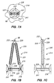
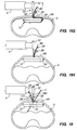
- the lifting apparatus according to the invention is used to lift a body wall according to the method to be described next with reference to Figures 11A-11H.
- a method of using the embodiment 10 of the lifting apparatus shown in Figures 1A-1F for lifting the lower abdominal wall will be described as an example.
- the method described can readily be adapted to lift other body walls using any of the alternative embodiments of the lifting apparatus described above.
- the lifting site is defined according to the treatment procedure that will follow the lifting.
- the center of the lifting site is then determined and a laparoscopic incision I is made through the abdominal wall AW, as shown in Figure 11A.
- the laparoscopic incision is normally between 10 and 15 mm long, depending on the cross sectional dimensions of the packaged body wall engaging element 24. Alternatively, a laparoscopic puncture of an equivalent size may be used.
- the proximal end 162 of the packaged body wall engaging element 24 is grasped, and the distal end 161 of the package is then inserted into the incision, as shown in Figure 11B.
- the inflation tube 26 and the tether 28 extend from the proximal end 162 of the package and lie adjacent to the arm attachment element 52. They may temporarily be attached to the arm attachment element for convenience during this part of the procedure.
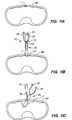
- the packaged body wall engaging element 24 is then advanced through the incision I in the abdominal wall AW until the proximal end 162 of the package clears the peritoneum P, as shown in Figures 11C and 11D.
- the packaged body wall engaging element is advanced through the abdominal wall, it is turned laterally, and the blunt, rounded distal tip 161 gently displaces the underlying viscera O downwards, away from the abdominal wall, and sideways, as shown in Figure 11C.
- Figure 11D shows the packaged body wall engaging element following its insertion though the abdominal wall.
- the packaged body wall engaging element lies between the peritoneum P and the viscera O with the proximal end 162 of the package 24 adjacent the incision I.
- the strap 58 of the flexible lifting element extends from the aperture 29 in the pouch, and runs between the pouch and the peritoneum to exit through the abdominal wall at the incision I.
- the inflation tube 26 and the tether 28 also exit through the abdominal wall at the incision.
- the arm attachment element 52 is then grasped and pulled proximally in the direction shown by the arrow 169 until a resistance is felt. Pulling the arm attachment element moves the packaged lifting apparatus 24 laterally, as indicated by the arrow 171 until the aperture 29 in the pouch 22 (and, hence, the central hole 32 of the body wall engaging element) is aligned with the incision I, as shown in Figure 11E.
- the bulb inflator 163 is then connected to the valve 80, and the bulb 165 is squeezed to feed inflation fluid, e.g., air, into the body wall engaging element 12.
- inflation fluid e.g., air
- the inflation fluid causes the packaged body wall engaging element 12 to unroll slightly.
- the resulting tension on the pouch 22 ruptures the pouch along the perforations 103 ( Figure 2A).
- the pouch remains attached to the body wall engaging element by the inflation tube 26 and the strap 58.
- the opened pouch is omitted from the Figures for clarity.
- the bulb 165 is then squeezed an additional number of times to feed more inflation fluid into the body wall engaging element 12. This inflates the body wall engaging element. As the body wall engaging element inflates it first unrolls fully, spreading laterally, and then inflates, spreading axially. This motion of the body wall engaging element keeps the viscera O out of the contact area between the body wall engaging element 12 and the abdominal wall.
- the bulb 165 is squeezed until the sound of air being vented from the valve 80 indicates that the pressure in the body wall engaging element has reached the working pressure set by the valve 80.
- the working pressure is high enough to provide the required degree of stiffness in the body wall engaging element, but is not so high as to compromise the reliability of the lifting apparatus.
- the bulb inflator 163 may be disconnected from the valve 80 at the end of the inflation operation. A one-way element in the valve 80 maintains the inflation pressure in the body wall engaging element when the bulb inflator is disconnected.
- the arm attachment element 52 When the body wall engaging element 12 is in its fully inflated state, the arm attachment element 52 is attached to the lifting arm A using the dovetail connector, as shown in Figure 11G. Raising the lifting arm A applies a lifting force to the arm attachment element, and thence, via the flexible element 50, to the body wall engaging element 12.
- the lifting surface 16 of the body wall engaging element applies the lifting force to a large area of the abdominal wall AW, which raises the abdominal wall to the position shown in Figure 11H. Lifting the abdominal wall creates the working space WS between the underside of the body wall engaging element 12 and the underlying organs O.
- part of the inflation tube 26 and part of the tether 28 run between the lifting surface 16 and the peritoneum P. These parts are not shown in Figures 11H and 11I.
- the body wall engaging element 12 may deform. If, as a result, the inflation pressure therein increases to a level approaching that which could compromise the reliability of the body wall engaging element, the valve 80 releases inflation fluid. This prevents the inflation pressure from increasing further, and maintains the reliability of the lifting apparatus.
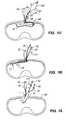
- an endoscope E shown schematically in Figure 11I, can be inserted into the incision I, and through the abdominal wall and the central hole 32 in the body wall engaging element to observe the underlying organs O.
- Figure 111 the parts of the body wall engaging element 12 bounding the central hole 32 are shown to indicate the freedom of lateral movement provided by the large central hole 32 for the endoscope.
- Figure 11I also shows the inflation tube 26, the tether 28 and one side 58A of the ship moved in the direction of the arrow 173 out of the way of the endoscope.
- the knob 68 of the arm attachment element 52 may be rotated to change the position of the strap 58.
- the endoscope can be left in position during the treatment procedure that follows the lifting procedure, and one or more surgical instruments can be passed into the working space through the incision and the central hole 32.
- a trocar tube can be inserted into the incision and through the central hole 32 once the abdominal wall has been lifted to provide a clean passage into the underlying working space.
- Additional instruments can be inserted into the working space through the incision I, or through trocar tubes driven through the abdominal wall AW outside the outer periphery of the body wall engaging element.
- the lifting arm A is lowered to restore the abdominal wall AW to its original (non-lifted) state. While the lifting arm is lowered, the flexibility of the strap 58 and ability of the dovetail connection between the dovetail connector ( Figure 5) on the arm attachment element and the lifting arm to disconnect together minimize the risk of the lifting arm applying a downwards force to the organs underlying the lifting apparatus.
- the arm attachment element 52 is disconnected from the lifting arm A, and the inlet connector 175 of bulb inflator 163 is connected to the valve 80, as shown in Figure 11J. This releases the inflation fluid from the body wall engaging element 12.
- the bulb 165 is then squeezed a number of times to evacuate the inflation fluid from the body wall engaging element. After the body wall engaging element is fully evacuated, it assumes the flat, disc-like shape shown in Figure 11K.
- the proximal end 92 of the tether 28 is then gently pulled proximally, as indicated by the arrow 177. This moves the evacuated body wall engaging element 12 laterally in the direction shown by the arrow 179 to align the part of the outer periphery to which the distal end 90 of the tether 28 is attached with the incision I, as shown in Figure 11K. Additional tension is then applied to the proximal end 92 of the tether pulls the portion of the evacuated body wall engaging element to which it is attached through the incision. This enables the evacuated body wall engaging element to be withdrawn edge-first from the abdominal cavity through the incision I, as shown in Figure 11L. The arm attachment element 52 is also pulled proximally during this process. The incision is then closed to finish the procedure.
- the lifting apparatus 10 may be used to lift a body wall manually, without the assistance of the lifting arm A.
- the body wall engaging element 12 is deployed under the body wall using the procedure described above with reference to Figures 11A-11F. Then, when the body wall engaging element is fully inflated, instead of connecting the arm engaging element 52 to the lifting arm, the surgeon grips the arm engaging element 52 and applies a lifting force to it. This raises the abdominal wall as shown in Figure 11H.
- the endoscope E can then be inserted into the incision and through the central hole 32 to provide viewing of the working space WS, as shown in Figure 11I.
- an element specially shaped to facilitate manual gripping can be substituted for the arm engaging element 52.
- the arm engaging element can be dispensed with entirely, and the lifting force can be applied manually directly to the strap 58.
Landscapes
- Health & Medical Sciences (AREA)
- Life Sciences & Earth Sciences (AREA)
- Surgery (AREA)
- Molecular Biology (AREA)
- General Health & Medical Sciences (AREA)
- Biomedical Technology (AREA)
- Heart & Thoracic Surgery (AREA)
- Medical Informatics (AREA)
- Nuclear Medicine, Radiotherapy & Molecular Imaging (AREA)
- Animal Behavior & Ethology (AREA)
- Engineering & Computer Science (AREA)
- Public Health (AREA)
- Veterinary Medicine (AREA)
- Surgical Instruments (AREA)
- Load-Engaging Elements For Cranes (AREA)
- Paper (AREA)
- Supplying Of Containers To The Packaging Station (AREA)
Claims (25)
- , Appareil (10; 10A, 110; 210; 310; 410) destiné à se déployer à travers une incision laparoscopique (I) pratiquée dans la paroi d'un corps dans le but d'exercer une force de soulèvement externe sur une grande surface de la paroi du corps, l'appareil comprenant :un élément de mise en contact avec la paroi du corps (12; 12A; 112; 212, 312; 412) capable de passer, à l'état comprimé, à travers l'incision laparoscopique (I) et apte à être gonflé pour prendre un état gonflé dans lequel l'élément de mise en contact avec la paroi du corps (12) est de forme essentiellement toroïdale, dispose d'une grande surface de soulèvement (16) et délimite un trou central (32), l'élément de mise en contact avec la paroi du corps (12; 12A; 112; 212, 312; 412) englobant une portion équatoriale (46) tournée vers le trou central; caractérisé en ce qu'il comprend en outre un élément flexible (14; 114, 214; 314; 414) englobant :une portion flexible (50) capable de passer à travers l'incision laparoscopique, la portion flexible étant fixée à la portion équatoriale (46) de l'élément de mise en contact avec la paroi du corps (12; 12A; 112; 212, 312; 412) et s'étendant depuis la portion équatoriale jusqu'à la grande surface de soulèvement (16), etun moyen d'adaptateur (52) relié à une partie de la portion flexible (50) éloignée de la portion équatoriale de l'élément de mise en contact avec la paroi du corps, destiné à recevoir la force de soulèvement externe et à transférer la force de soulèvement externe à la portion flexible (50).
- Appareil (10) selon la revendication 1, caractérisé en ce que l'élément de mise en contact avec la paroi du corps (12) englobe :une moitié supérieure d'enveloppe annulaire (34),une moitié inférieure d'enveloppe annulaire (36), les moitiés d'enveloppe (34, 36) englobant chacune une zone périphérique interne (44) et une zone périphérique externe (45);la zone périphérique externe (45) de la moitié supérieure d'enveloppe (34) est reliée à la zone périphérique externe (45) de la moitié inférieure d'enveloppe (36) pour former une soudure externe;la zone périphérique interne (44) de la moitié supérieure d'enveloppe (34) est reliée à la zone périphérique interne (44) de la moitié inférieure d'enveloppe (36) pour former une zone de soulèvement (48); etla portion flexible (50) est fixée à la zone de soulèvement (48).
- Appareil (10) selon la revendication 2, caractérisé en ce que les moitiés d'enveloppe (34, 36) comprennent chacune une matière composite englobant une partie centrale en tissu.
- Appareil (10) selon la revendication 2, caractérisé en ce que les moitiés d'enveloppe (34, 36) renferment ensemble une chambre, et
la soudure externe (42) est logée à l'intérieur de la chambre, les moitiés d'enveloppe (34, 36) isolant la soudure externe (42) par rapport à la paroi du corps. - Appareil (10) selon la revendication 4, caractérisé en ce que les moitiés d'enveloppe (34, 36) comprennent chacune une matière composite englobant une partie centrale en tissu.
- Appareil (10) selon la revendication 4, caractérisé en ce que les moitiés d'enveloppe (34, 36) comprennent chacune une matière composite englobant une partie centrale en tissu tissé constitué par des filés auxquels on a appliqué un traitement pour empêcher la fuite du fluide de gonflage le long des filés.
- Appareil (10) selon la revendication 2, caractérisé en ce que les moitiés d'enveloppe (34, 36) comprennent chacune une matière composite englobant une partie centrale en tissu possédant une direction de fil de chaíne; et
la zone périphérique externe (45) de la moitié supérieure d'enveloppe (34) est reliée à la zone périphérique externe (45) de la moitié inférieure d'enveloppe (36), la direction de fil de chaíne (57) de la matière composite de la moitié supérieure d'enveloppe (34) manifestant un décalage angulaire par rapport à la direction de fil de chaíne de la matière composite de la moitié inférieure d'enveloppe (36) afin de conférer à l'élément entrant en contact avec la paroi du corps (12) une configuration essentiellement circulaire, sans prendre en compte la partie centrale en tissu tissé de la matière composite. - Appareil (410) selon la revendication 2, caractérisé en ce que l'élément entrant en contact avec la paroi du corps (412) comprend en outre une chicane (437) entourant le trou central (432) et reliant l'une à l'autre la moitié supérieure d'enveloppe (434) et la moitié inférieure d'enveloppe (436).
- Appareil (410) selon la revendication 8, caractérisé en ce que l'élément entrant en contact avec la paroi du corps (412) comprend en outre une chicane supplémentaire (467) délimitant le trou central (432), la chicane supplémentaire (467) englobant :une moitié supérieure de chicane fixée à la zone périphérique interne (444) de la moitié supérieure d'enveloppe (434) et englobant une zone de fixation supérieure éloignée de la moitié supérieure d'enveloppe (434),une chicane inférieure fixée à la zone périphérique interne (444) de la moitié inférieure d'enveloppe (436) et englobant une zone de fixation inférieure éloignée de la moitié inférieure d'enveloppe (436), la zone de fixation supérieure étant fixée à la zone de fixation inférieure pour former la zone de soulèvement.
- Appareil (10) selon la revendication 1, caractérisé en ce que l'élément entrant en contact avec la paroi du corps (12) possède une hauteur et une largeur radiale, la hauteur étant inférieure à la moitié de la largeur radiale.
- Appareil (10) selon la revendication 1, caractérisé en ce que la portion flexible (50) de l'élément de soulèvement flexible (14) est réalisé à partir d'une pièce unique de matière et englobe deux portions semi-annulaires (56) reliées l'une à l'autre par une sangle allongée (58), les deux portions semi-annulaires (56) étant disposées de manière symétrique autour de la sangle allongée (58) en direction longitudinale et en direction latérale, et étant dimensionnées de façon à recouvrir ensemble la zone équatoriale de l'élément entrant en contact avec la paroi du corps (12), la sangle (58) formant une boucle à laquelle est fixé le moyen d'adaptateur (52).
- Appareil (10) selon la revendication 11, caractérisé en ce que la portion flexible (50) est réalisée à partir d'une pièce unique de matière composite englobant une partie centrale en tissu tissé comprenant des fils de chaínes (57), les fils de chaínes (57) étant disposés en alignement en direction longitudinale le long de la sangle (58).
- Appareil (110) selon la revendication 1, caractérisé en ce que la portion flexible (114) englobeun anneau supérieur essentiellement rigide (121) et un anneau inférieur essentiellement rigide (123) concentrique avec le trou central (132) et disposés sur les côtés opposés de la portion équatoriale de l'élément entrant en contact avec la paroi du corps; etun élément flexible allongé (125) fixé à l'anneau supérieur (121) et à l'anneau inférieur (123), l'élément flexible (125) formant une boucle à laquelle est fixé le moyen d'adaptateur (52).
- Appareil (110) selon la revendication 13, caractérisé en ce que l'anneau supérieur (121) et l'anneau inférieur (123), respectivement, délimitent plusieurs trous axiaux;
l'élément flexible (114) possède des extrémités opposées et est vissé à travers les trous pratiqués dans l'anneau supérieur (121), l'anneau inférieur (123) et la région équatoriale, les extrémités opposées étant jointes l'une à l'autre. - Appareil (210) selon la revendication 1, caractérisé en ce que la portion flexible (214) englobe:un anneau (241) concentrique avec le trou central et fixé à une partie de la portion équatoriale de l'élément entrant en contact avec la paroi du corps, éloignée de la surface de soulèvement (248); etun élément flexible allongé (225) fixé à l'anneau (241) et formant une boucle à laquelle est fixé le moyen d'adaptateur (52).
- Appareil (210) selon la revendication 15, caractérisé en ce que l'anneau (241) délimite plusieurs trous axiaux (227);la région équatoriale de l'élément entrant en contact avec la paroi du corps (212) délimite plusieurs trous disposés en alignement avec les trous axiaux pratiqués dans l'anneau; etl'élément flexible (220) possède des extrémités opposées et est vissé à travers les trous (227) pratiqués dans l'anneau et dans la région équatoriale, les extrémités opposées étant jointes l'une à l'autre.
- Appareil (210) selon la revendication 15, caractérisé en ce que l'anneau (241) est réalisé à partir d'une seule pièce de matière composite englobant une partie centrale en tissu tissé comprenant des fils de chaínes arrangés en position circulaire et des fils de trames tissés pour procurer des lisières opposées.
- Appareil (310) selon la revendication 1, dans lequel la portion flexible englobe :un segment de transfert (341, 343) fixé à la portion équatoriale de la paroi du corps sur chacun des côtés opposés du trou central, chaque segment de transfert (341, 343) étant réalisé à partir d'une pièce de matière composite englobant une partie centrale constituée d'un ruban en tissu tissé qui possède des lisières opposées (345), une des lisières étant tournée vers le trou central; etun élément flexible allongé (325) fixé à chaque segment de transfert et formant une boucle à laquelle est fixé l'élément d'adaptateur.
- Appareil (310) selon la revendication 18, dans lequel:chaque segment de transfert (341, 343) délimite un trou axial; etl'élément flexible (325) possède des extrémités opposées et est vissé à travers le trou pratiqué dans chaque segment de transfert.
- Appareil (10) selon la revendication 1, caractérisé en ce que le moyen d'adaptateur (52) englobe:un boítier (60) essentiellement cylindrique;une broche disposée dans le boítier, à laquelle est fixé l'élément de soulèvement flexible (14); etun connecteur en queue d'aronde (64) monté sur le boítier (60).
- Appareil selon la revendication 20, dans lequel le moyen d'adaptateur (52) englobant en outre un dispositif de suspension de sangle (62) comportant un alésage latéral (88) dans lequel vient se loger la broche.
- Appareil (10) selon la revendication 1, caractérisé en ce que l'élément entrant en contact avec la paroi du corps (12) possède une périphérie externe, et
l'appareil (10) comprend en outre une amarre allongée (28) dont une extrémité est fixée à l'élément entrant en contact avec la paroi du corps (12) en position adjacente à la périphérie externe. - Appareil (10) selon la revendication 1, caractérisé en ce qu'il comprend en outre un moyen de tube de gonflage (26) destiné à gonfler l'élément entrant en contact avec la paroi du corps (12), le moyen de tube de gonflage (26) englobant un moyen de réglage de la pression (80) pour limiter la pression régnant dans l'élément entrant en contact avec la paroi du corps (12).
- Appareil (10) selon la revendication 1, caractérisé en ce qu'il comprend en outre un moyen de tube de gonflage (26) destiné à gonfler l'élément entrant en contact avec la paroi du corps (12), le moyen de tube de gonflage (26) englobant un moyen (27) s'opposant à la formation de coques pour empêcher la formation de coques sur le moyen de tube de gonflage (26).
- Appareil (10) selon la revendication 24, caractérisé en ce que le moyen de tube de gonflage (26) comprend un tube flexible allongé comportant un alésage, et
le moyen (27) s'opposant à la formation de coques comprenant une longueur de monofilament insérée dans l'alésage du tube flexible allongé (26).
Applications Claiming Priority (3)
| Application Number | Priority Date | Filing Date | Title |
|---|---|---|---|
| US08/403,458 US5681341A (en) | 1995-03-14 | 1995-03-14 | Flexible lifting apparatus |
| US403458 | 1995-03-14 | ||
| PCT/US1996/002897 WO1996028099A1 (fr) | 1995-03-14 | 1996-03-01 | Appareil de soulevement flexible |
Publications (2)
| Publication Number | Publication Date |
|---|---|
| EP0814705A1 EP0814705A1 (fr) | 1998-01-07 |
| EP0814705B1 true EP0814705B1 (fr) | 2001-09-05 |
Family
ID=23595857
Family Applications (1)
| Application Number | Title | Priority Date | Filing Date |
|---|---|---|---|
| EP96907919A Expired - Lifetime EP0814705B1 (fr) | 1995-03-14 | 1996-03-01 | Appareil de soulevement flexible |
Country Status (8)
| Country | Link |
|---|---|
| US (2) | US5681341A (fr) |
| EP (1) | EP0814705B1 (fr) |
| JP (1) | JP3676372B2 (fr) |
| AT (1) | ATE205067T1 (fr) |
| CA (1) | CA2214632C (fr) |
| DE (1) | DE69615008T2 (fr) |
| ES (1) | ES2177770T3 (fr) |
| WO (1) | WO1996028099A1 (fr) |
Families Citing this family (443)
| Publication number | Priority date | Publication date | Assignee | Title |
|---|---|---|---|---|
| US6814700B1 (en) * | 1996-03-04 | 2004-11-09 | Heartport, Inc. | Soft tissue retractor and method for providing surgical access |
| US6048309A (en) * | 1996-03-04 | 2000-04-11 | Heartport, Inc. | Soft tissue retractor and delivery device therefor |
| US6015421A (en) * | 1997-05-15 | 2000-01-18 | General Surgical Innovations, Inc. | Apparatus and method for developing an anatomic space for laparoscopic procedures |
| US6042539A (en) * | 1999-03-26 | 2000-03-28 | Ethicon Endo-Surgery, Inc. | Vacuum-actuated tissue-lifting device and method |
| US6083155A (en) * | 1999-04-16 | 2000-07-04 | Nuvue Technologies, L.L.C. | Eyelid speculum |
| DE10040774A1 (de) * | 2000-08-21 | 2002-03-28 | Ebert Dieter | Vorrichtung zur Ermöglichung freier Sicht auf eine chirurgische Behandlungsstelle |
| US7473221B2 (en) | 2000-10-19 | 2009-01-06 | Applied Medical Resources Corporation | Surgical access apparatus and method |
| US6935889B2 (en) * | 2001-02-28 | 2005-08-30 | Koninklijke Philips Electronics N.V. | Electrode-pad package that is removable from an electrode-pad lead and method for opening the package |
| EP2422829B1 (fr) | 2001-08-14 | 2013-03-06 | Applied Medical Resources Corporation | Appareil de fermeture hermetique d'un acces chirurgical |
| US6958037B2 (en) | 2001-10-20 | 2005-10-25 | Applied Medical Resources Corporation | Wound retraction apparatus and method |
| US20030130621A1 (en) * | 2002-01-04 | 2003-07-10 | Bryan Vincent E. | Spinal needle system |
| CA2488118C (fr) | 2002-06-05 | 2012-01-10 | Applied Medical Resources Corporation | Ecarteur |
| US20050020884A1 (en) | 2003-02-25 | 2005-01-27 | Hart Charles C. | Surgical access system |
| US20070084897A1 (en) | 2003-05-20 | 2007-04-19 | Shelton Frederick E Iv | Articulating surgical stapling instrument incorporating a two-piece e-beam firing mechanism |
| US9060770B2 (en) | 2003-05-20 | 2015-06-23 | Ethicon Endo-Surgery, Inc. | Robotically-driven surgical instrument with E-beam driver |
| WO2005013803A2 (fr) | 2003-08-06 | 2005-02-17 | Applied Medical Resources Corporation | Dispositif chirurgical avec gel non adhesif et procede d'elaboration |
| US7163510B2 (en) | 2003-09-17 | 2007-01-16 | Applied Medical Resources Corporation | Surgical instrument access device |
| US8215531B2 (en) | 2004-07-28 | 2012-07-10 | Ethicon Endo-Surgery, Inc. | Surgical stapling instrument having a medical substance dispenser |
| US11896225B2 (en) | 2004-07-28 | 2024-02-13 | Cilag Gmbh International | Staple cartridge comprising a pan |
| US20070078476A1 (en) * | 2004-10-12 | 2007-04-05 | Hull Wendell C Sr | Overweight control apparatuses for insertion into the stomach |
| US7799078B2 (en) * | 2004-11-12 | 2010-09-21 | Warsaw Orthopedic, Inc. | Implantable vertebral lift |
| US7566302B2 (en) * | 2005-07-28 | 2009-07-28 | Synthes Usa, Llc | Expandable access device |
| US11246590B2 (en) | 2005-08-31 | 2022-02-15 | Cilag Gmbh International | Staple cartridge including staple drivers having different unfired heights |
| US7669746B2 (en) | 2005-08-31 | 2010-03-02 | Ethicon Endo-Surgery, Inc. | Staple cartridges for forming staples having differing formed staple heights |
| US10159482B2 (en) | 2005-08-31 | 2018-12-25 | Ethicon Llc | Fastener cartridge assembly comprising a fixed anvil and different staple heights |
| US8991676B2 (en) | 2007-03-15 | 2015-03-31 | Ethicon Endo-Surgery, Inc. | Surgical staple having a slidable crown |
| US9237891B2 (en) | 2005-08-31 | 2016-01-19 | Ethicon Endo-Surgery, Inc. | Robotically-controlled surgical stapling devices that produce formed staples having different lengths |
| US7934630B2 (en) | 2005-08-31 | 2011-05-03 | Ethicon Endo-Surgery, Inc. | Staple cartridges for forming staples having differing formed staple heights |
| US11484312B2 (en) | 2005-08-31 | 2022-11-01 | Cilag Gmbh International | Staple cartridge comprising a staple driver arrangement |
| DE602006015073D1 (de) | 2005-10-14 | 2010-08-05 | Applied Med Resources | Laparoskopische handzugriffsvorrichtung |
| US20070106317A1 (en) | 2005-11-09 | 2007-05-10 | Shelton Frederick E Iv | Hydraulically and electrically actuated articulation joints for surgical instruments |
| US20120292367A1 (en) | 2006-01-31 | 2012-11-22 | Ethicon Endo-Surgery, Inc. | Robotically-controlled end effector |
| US11793518B2 (en) | 2006-01-31 | 2023-10-24 | Cilag Gmbh International | Powered surgical instruments with firing system lockout arrangements |
| US8820603B2 (en) | 2006-01-31 | 2014-09-02 | Ethicon Endo-Surgery, Inc. | Accessing data stored in a memory of a surgical instrument |
| US7753904B2 (en) | 2006-01-31 | 2010-07-13 | Ethicon Endo-Surgery, Inc. | Endoscopic surgical instrument with a handle that can articulate with respect to the shaft |
| US7845537B2 (en) | 2006-01-31 | 2010-12-07 | Ethicon Endo-Surgery, Inc. | Surgical instrument having recording capabilities |
| US8708213B2 (en) | 2006-01-31 | 2014-04-29 | Ethicon Endo-Surgery, Inc. | Surgical instrument having a feedback system |
| US11278279B2 (en) | 2006-01-31 | 2022-03-22 | Cilag Gmbh International | Surgical instrument assembly |
| US20110024477A1 (en) | 2009-02-06 | 2011-02-03 | Hall Steven G | Driven Surgical Stapler Improvements |
| US8186555B2 (en) | 2006-01-31 | 2012-05-29 | Ethicon Endo-Surgery, Inc. | Motor-driven surgical cutting and fastening instrument with mechanical closure system |
| US11224427B2 (en) | 2006-01-31 | 2022-01-18 | Cilag Gmbh International | Surgical stapling system including a console and retraction assembly |
| US20110295295A1 (en) | 2006-01-31 | 2011-12-01 | Ethicon Endo-Surgery, Inc. | Robotically-controlled surgical instrument having recording capabilities |
| US8992422B2 (en) | 2006-03-23 | 2015-03-31 | Ethicon Endo-Surgery, Inc. | Robotically-controlled endoscopic accessory channel |
| US8322455B2 (en) | 2006-06-27 | 2012-12-04 | Ethicon Endo-Surgery, Inc. | Manually driven surgical cutting and fastening instrument |
| US10568652B2 (en) | 2006-09-29 | 2020-02-25 | Ethicon Llc | Surgical staples having attached drivers of different heights and stapling instruments for deploying the same |
| US8485412B2 (en) | 2006-09-29 | 2013-07-16 | Ethicon Endo-Surgery, Inc. | Surgical staples having attached drivers and stapling instruments for deploying the same |
| US11980366B2 (en) | 2006-10-03 | 2024-05-14 | Cilag Gmbh International | Surgical instrument |
| US8684253B2 (en) | 2007-01-10 | 2014-04-01 | Ethicon Endo-Surgery, Inc. | Surgical instrument with wireless communication between a control unit of a robotic system and remote sensor |
| US8652120B2 (en) | 2007-01-10 | 2014-02-18 | Ethicon Endo-Surgery, Inc. | Surgical instrument with wireless communication between control unit and sensor transponders |
| US11291441B2 (en) | 2007-01-10 | 2022-04-05 | Cilag Gmbh International | Surgical instrument with wireless communication between control unit and remote sensor |
| US20080169332A1 (en) | 2007-01-11 | 2008-07-17 | Shelton Frederick E | Surgical stapling device with a curved cutting member |
| US11039836B2 (en) | 2007-01-11 | 2021-06-22 | Cilag Gmbh International | Staple cartridge for use with a surgical stapling instrument |
| US8893946B2 (en) | 2007-03-28 | 2014-11-25 | Ethicon Endo-Surgery, Inc. | Laparoscopic tissue thickness and clamp load measuring devices |
| EP2719340B1 (fr) | 2007-05-11 | 2017-02-08 | Applied Medical Resources Corporation | Rétracteur chirurgical |
| CA2682923C (fr) | 2007-05-11 | 2014-10-07 | Applied Medical Resources Corporation | Ecarteur chirurgical avec coussin de gel |
| US11672531B2 (en) | 2007-06-04 | 2023-06-13 | Cilag Gmbh International | Rotary drive systems for surgical instruments |
| US8931682B2 (en) | 2007-06-04 | 2015-01-13 | Ethicon Endo-Surgery, Inc. | Robotically-controlled shaft based rotary drive systems for surgical instruments |
| US7753245B2 (en) | 2007-06-22 | 2010-07-13 | Ethicon Endo-Surgery, Inc. | Surgical stapling instruments |
| US11849941B2 (en) | 2007-06-29 | 2023-12-26 | Cilag Gmbh International | Staple cartridge having staple cavities extending at a transverse angle relative to a longitudinal cartridge axis |
| AU2009206407B2 (en) | 2008-01-22 | 2014-04-24 | Applied Medical Resources Corporation | Surgical instrument access device |
| US8758391B2 (en) | 2008-02-14 | 2014-06-24 | Ethicon Endo-Surgery, Inc. | Interchangeable tools for surgical instruments |
| US8636736B2 (en) | 2008-02-14 | 2014-01-28 | Ethicon Endo-Surgery, Inc. | Motorized surgical cutting and fastening instrument |
| US7866527B2 (en) | 2008-02-14 | 2011-01-11 | Ethicon Endo-Surgery, Inc. | Surgical stapling apparatus with interlockable firing system |
| US11986183B2 (en) | 2008-02-14 | 2024-05-21 | Cilag Gmbh International | Surgical cutting and fastening instrument comprising a plurality of sensors to measure an electrical parameter |
| US8573465B2 (en) | 2008-02-14 | 2013-11-05 | Ethicon Endo-Surgery, Inc. | Robotically-controlled surgical end effector system with rotary actuated closure systems |
| RU2493788C2 (ru) | 2008-02-14 | 2013-09-27 | Этикон Эндо-Серджери, Инк. | Хирургический режущий и крепежный инструмент, имеющий радиочастотные электроды |
| US7819298B2 (en) | 2008-02-14 | 2010-10-26 | Ethicon Endo-Surgery, Inc. | Surgical stapling apparatus with control features operable with one hand |
| US9179912B2 (en) | 2008-02-14 | 2015-11-10 | Ethicon Endo-Surgery, Inc. | Robotically-controlled motorized surgical cutting and fastening instrument |
| US20130153641A1 (en) | 2008-02-15 | 2013-06-20 | Ethicon Endo-Surgery, Inc. | Releasable layer of material and surgical end effector having the same |
| US11272927B2 (en) | 2008-02-15 | 2022-03-15 | Cilag Gmbh International | Layer arrangements for surgical staple cartridges |
| WO2009117358A2 (fr) * | 2008-03-18 | 2009-09-24 | The Trustees Of The University Of Pennsylvania | Ecarteur pour trauma |
| US9386983B2 (en) | 2008-09-23 | 2016-07-12 | Ethicon Endo-Surgery, Llc | Robotically-controlled motorized surgical instrument |
| US9005230B2 (en) | 2008-09-23 | 2015-04-14 | Ethicon Endo-Surgery, Inc. | Motorized surgical instrument |
| US11648005B2 (en) | 2008-09-23 | 2023-05-16 | Cilag Gmbh International | Robotically-controlled motorized surgical instrument with an end effector |
| US8210411B2 (en) | 2008-09-23 | 2012-07-03 | Ethicon Endo-Surgery, Inc. | Motor-driven surgical cutting instrument |
| US8608045B2 (en) | 2008-10-10 | 2013-12-17 | Ethicon Endo-Sugery, Inc. | Powered surgical cutting and stapling apparatus with manually retractable firing system |
| EP2349032B1 (fr) | 2008-10-13 | 2017-12-06 | Applied Medical Resources Corporation | Système d'accès à orifice unique |
| US8517239B2 (en) | 2009-02-05 | 2013-08-27 | Ethicon Endo-Surgery, Inc. | Surgical stapling instrument comprising a magnetic element driver |
| US8444036B2 (en) | 2009-02-06 | 2013-05-21 | Ethicon Endo-Surgery, Inc. | Motor driven surgical fastener device with mechanisms for adjusting a tissue gap within the end effector |
| WO2010090940A1 (fr) | 2009-02-06 | 2010-08-12 | Ethicon Endo-Surgery, Inc. | Améliorations d'agrafeuse chirurgicale commandée |
| ES2776949T3 (es) | 2009-08-31 | 2020-08-03 | Applied Med Resources | Sistema de acceso quirúrgico multifuncional |
| US8220688B2 (en) | 2009-12-24 | 2012-07-17 | Ethicon Endo-Surgery, Inc. | Motor-driven surgical cutting instrument with electric actuator directional control assembly |
| US8851354B2 (en) | 2009-12-24 | 2014-10-07 | Ethicon Endo-Surgery, Inc. | Surgical cutting instrument that analyzes tissue thickness |
| US8783543B2 (en) | 2010-07-30 | 2014-07-22 | Ethicon Endo-Surgery, Inc. | Tissue acquisition arrangements and methods for surgical stapling devices |
| US8360296B2 (en) | 2010-09-09 | 2013-01-29 | Ethicon Endo-Surgery, Inc. | Surgical stapling head assembly with firing lockout for a surgical stapler |
| US11298125B2 (en) | 2010-09-30 | 2022-04-12 | Cilag Gmbh International | Tissue stapler having a thickness compensator |
| US9282962B2 (en) | 2010-09-30 | 2016-03-15 | Ethicon Endo-Surgery, Llc | Adhesive film laminate |
| US9517063B2 (en) | 2012-03-28 | 2016-12-13 | Ethicon Endo-Surgery, Llc | Movable member for use with a tissue thickness compensator |
| US9364233B2 (en) | 2010-09-30 | 2016-06-14 | Ethicon Endo-Surgery, Llc | Tissue thickness compensators for circular surgical staplers |
| US11849952B2 (en) | 2010-09-30 | 2023-12-26 | Cilag Gmbh International | Staple cartridge comprising staples positioned within a compressible portion thereof |
| US9168038B2 (en) | 2010-09-30 | 2015-10-27 | Ethicon Endo-Surgery, Inc. | Staple cartridge comprising a tissue thickness compensator |
| US9629814B2 (en) | 2010-09-30 | 2017-04-25 | Ethicon Endo-Surgery, Llc | Tissue thickness compensator configured to redistribute compressive forces |
| US9351730B2 (en) | 2011-04-29 | 2016-05-31 | Ethicon Endo-Surgery, Llc | Tissue thickness compensator comprising channels |
| US10945731B2 (en) | 2010-09-30 | 2021-03-16 | Ethicon Llc | Tissue thickness compensator comprising controlled release and expansion |
| US11812965B2 (en) | 2010-09-30 | 2023-11-14 | Cilag Gmbh International | Layer of material for a surgical end effector |
| US9320523B2 (en) | 2012-03-28 | 2016-04-26 | Ethicon Endo-Surgery, Llc | Tissue thickness compensator comprising tissue ingrowth features |
| EP2621348B1 (fr) | 2010-10-01 | 2019-06-12 | Applied Medical Resources Corporation | Système de chirurgie pour orifice naturel |
| US8695866B2 (en) | 2010-10-01 | 2014-04-15 | Ethicon Endo-Surgery, Inc. | Surgical instrument having a power control circuit |
| US9289115B2 (en) | 2010-10-01 | 2016-03-22 | Applied Medical Resources Corporation | Natural orifice surgery system |
| US9113883B2 (en) | 2011-03-14 | 2015-08-25 | Ethicon Endo-Surgery, Inc. | Collapsible anvil plate assemblies for circular surgical stapling devices |
| JP5674545B2 (ja) * | 2011-04-22 | 2015-02-25 | オオサキメディカル株式会社 | 肝臓吊上げ圧排具 |
| BR112013027794B1 (pt) | 2011-04-29 | 2020-12-15 | Ethicon Endo-Surgery, Inc | Conjunto de cartucho de grampos |
| EP3711682B1 (fr) | 2011-05-10 | 2022-10-19 | Applied Medical Resources Corporation | Écarteur de plaies |
| US9072535B2 (en) | 2011-05-27 | 2015-07-07 | Ethicon Endo-Surgery, Inc. | Surgical stapling instruments with rotatable staple deployment arrangements |
| US11207064B2 (en) | 2011-05-27 | 2021-12-28 | Cilag Gmbh International | Automated end effector component reloading system for use with a robotic system |
| US9044230B2 (en) | 2012-02-13 | 2015-06-02 | Ethicon Endo-Surgery, Inc. | Surgical cutting and fastening instrument with apparatus for determining cartridge and firing motion status |
| RU2644272C2 (ru) | 2012-03-28 | 2018-02-08 | Этикон Эндо-Серджери, Инк. | Узел ограничения, включающий компенсатор толщины ткани |
| BR112014024098B1 (pt) | 2012-03-28 | 2021-05-25 | Ethicon Endo-Surgery, Inc. | cartucho de grampos |
| JP6305979B2 (ja) | 2012-03-28 | 2018-04-04 | エシコン・エンド−サージェリィ・インコーポレイテッドEthicon Endo−Surgery,Inc. | 複数の層を含む組織厚さコンペンセーター |
| US9101358B2 (en) | 2012-06-15 | 2015-08-11 | Ethicon Endo-Surgery, Inc. | Articulatable surgical instrument comprising a firing drive |
| US9649111B2 (en) | 2012-06-28 | 2017-05-16 | Ethicon Endo-Surgery, Llc | Replaceable clip cartridge for a clip applier |
| US9226751B2 (en) | 2012-06-28 | 2016-01-05 | Ethicon Endo-Surgery, Inc. | Surgical instrument system including replaceable end effectors |
| JP6290201B2 (ja) | 2012-06-28 | 2018-03-07 | エシコン・エンド−サージェリィ・インコーポレイテッドEthicon Endo−Surgery,Inc. | 空クリップカートリッジ用のロックアウト |
| US20140001231A1 (en) | 2012-06-28 | 2014-01-02 | Ethicon Endo-Surgery, Inc. | Firing system lockout arrangements for surgical instruments |
| US11202631B2 (en) | 2012-06-28 | 2021-12-21 | Cilag Gmbh International | Stapling assembly comprising a firing lockout |
| BR112014032776B1 (pt) | 2012-06-28 | 2021-09-08 | Ethicon Endo-Surgery, Inc | Sistema de instrumento cirúrgico e kit cirúrgico para uso com um sistema de instrumento cirúrgico |
| US9289256B2 (en) | 2012-06-28 | 2016-03-22 | Ethicon Endo-Surgery, Llc | Surgical end effectors having angled tissue-contacting surfaces |
| US20140005718A1 (en) | 2012-06-28 | 2014-01-02 | Ethicon Endo-Surgery, Inc. | Multi-functional powered surgical device with external dissection features |
| MX368026B (es) | 2013-03-01 | 2019-09-12 | Ethicon Endo Surgery Inc | Instrumento quirúrgico articulable con vías conductoras para la comunicación de la señal. |
| RU2669463C2 (ru) | 2013-03-01 | 2018-10-11 | Этикон Эндо-Серджери, Инк. | Хирургический инструмент с мягким упором |
| US9629629B2 (en) | 2013-03-14 | 2017-04-25 | Ethicon Endo-Surgey, LLC | Control systems for surgical instruments |
| US9808244B2 (en) | 2013-03-14 | 2017-11-07 | Ethicon Llc | Sensor arrangements for absolute positioning system for surgical instruments |
| CA2902201A1 (fr) | 2013-03-15 | 2014-09-18 | Applied Medical Resources Corporation | Dispositif d'acces chirurgical a gel mecanique |
| BR112015026109B1 (pt) | 2013-04-16 | 2022-02-22 | Ethicon Endo-Surgery, Inc | Instrumento cirúrgico |
| US9867612B2 (en) | 2013-04-16 | 2018-01-16 | Ethicon Llc | Powered surgical stapler |
| US9808231B2 (en) | 2013-07-09 | 2017-11-07 | Edwards Lifesciences Corporation | Tissue retractor |
| RU2678363C2 (ru) | 2013-08-23 | 2019-01-28 | ЭТИКОН ЭНДО-СЕРДЖЕРИ, ЭлЭлСи | Устройства втягивания пускового элемента для хирургических инструментов с электропитанием |
| US20150053743A1 (en) | 2013-08-23 | 2015-02-26 | Ethicon Endo-Surgery, Inc. | Error detection arrangements for surgical instrument assemblies |
| US9962161B2 (en) | 2014-02-12 | 2018-05-08 | Ethicon Llc | Deliverable surgical instrument |
| BR112016019387B1 (pt) | 2014-02-24 | 2022-11-29 | Ethicon Endo-Surgery, Llc | Sistema de instrumento cirúrgico e cartucho de prendedores para uso com um instrumento cirúrgico de fixação |
| US20150272582A1 (en) | 2014-03-26 | 2015-10-01 | Ethicon Endo-Surgery, Inc. | Power management control systems for surgical instruments |
| US10004497B2 (en) | 2014-03-26 | 2018-06-26 | Ethicon Llc | Interface systems for use with surgical instruments |
| US9804618B2 (en) | 2014-03-26 | 2017-10-31 | Ethicon Llc | Systems and methods for controlling a segmented circuit |
| BR112016021943B1 (pt) | 2014-03-26 | 2022-06-14 | Ethicon Endo-Surgery, Llc | Instrumento cirúrgico para uso por um operador em um procedimento cirúrgico |
| US10426476B2 (en) | 2014-09-26 | 2019-10-01 | Ethicon Llc | Circular fastener cartridges for applying radially expandable fastener lines |
| JP6636452B2 (ja) | 2014-04-16 | 2020-01-29 | エシコン エルエルシーEthicon LLC | 異なる構成を有する延在部を含む締結具カートリッジ |
| US20150297225A1 (en) | 2014-04-16 | 2015-10-22 | Ethicon Endo-Surgery, Inc. | Fastener cartridges including extensions having different configurations |
| JP6612256B2 (ja) | 2014-04-16 | 2019-11-27 | エシコン エルエルシー | 不均一な締結具を備える締結具カートリッジ |
| JP6532889B2 (ja) | 2014-04-16 | 2019-06-19 | エシコン エルエルシーEthicon LLC | 締結具カートリッジ組立体及びステープル保持具カバー配置構成 |
| US9844369B2 (en) | 2014-04-16 | 2017-12-19 | Ethicon Llc | Surgical end effectors with firing element monitoring arrangements |
| CA2952640C (fr) | 2014-07-18 | 2023-04-04 | Applied Medical Resources Corporation | Gels presentant des revetements non collants permanents et procede de fabrication |
| KR102380957B1 (ko) | 2014-08-15 | 2022-03-31 | 어플라이드 메디컬 리소시스 코포레이션 | 자연 개구 수술 시스템 |
| BR112017004361B1 (pt) | 2014-09-05 | 2023-04-11 | Ethicon Llc | Sistema eletrônico para um instrumento cirúrgico |
| US11311294B2 (en) | 2014-09-05 | 2022-04-26 | Cilag Gmbh International | Powered medical device including measurement of closure state of jaws |
| US10016199B2 (en) | 2014-09-05 | 2018-07-10 | Ethicon Llc | Polarity of hall magnet to identify cartridge type |
| US10105142B2 (en) | 2014-09-18 | 2018-10-23 | Ethicon Llc | Surgical stapler with plurality of cutting elements |
| CN107427300B (zh) | 2014-09-26 | 2020-12-04 | 伊西康有限责任公司 | 外科缝合支撑物和辅助材料 |
| US11523821B2 (en) | 2014-09-26 | 2022-12-13 | Cilag Gmbh International | Method for creating a flexible staple line |
| US10076325B2 (en) | 2014-10-13 | 2018-09-18 | Ethicon Llc | Surgical stapling apparatus comprising a tissue stop |
| US9924944B2 (en) | 2014-10-16 | 2018-03-27 | Ethicon Llc | Staple cartridge comprising an adjunct material |
| US11141153B2 (en) | 2014-10-29 | 2021-10-12 | Cilag Gmbh International | Staple cartridges comprising driver arrangements |
| US10517594B2 (en) | 2014-10-29 | 2019-12-31 | Ethicon Llc | Cartridge assemblies for surgical staplers |
| US9844376B2 (en) | 2014-11-06 | 2017-12-19 | Ethicon Llc | Staple cartridge comprising a releasable adjunct material |
| US9949730B2 (en) | 2014-11-25 | 2018-04-24 | Applied Medical Resources Corporation | Circumferential wound retraction with support and guidance structures |
| US10736636B2 (en) | 2014-12-10 | 2020-08-11 | Ethicon Llc | Articulatable surgical instrument system |
| US9844375B2 (en) | 2014-12-18 | 2017-12-19 | Ethicon Llc | Drive arrangements for articulatable surgical instruments |
| US10188385B2 (en) | 2014-12-18 | 2019-01-29 | Ethicon Llc | Surgical instrument system comprising lockable systems |
| US9987000B2 (en) | 2014-12-18 | 2018-06-05 | Ethicon Llc | Surgical instrument assembly comprising a flexible articulation system |
| US10245027B2 (en) | 2014-12-18 | 2019-04-02 | Ethicon Llc | Surgical instrument with an anvil that is selectively movable about a discrete non-movable axis relative to a staple cartridge |
| MX2017008108A (es) | 2014-12-18 | 2018-03-06 | Ethicon Llc | Instrumento quirurgico con un yunque que puede moverse de manera selectiva sobre un eje discreto no movil con relacion a un cartucho de grapas. |
| US10085748B2 (en) | 2014-12-18 | 2018-10-02 | Ethicon Llc | Locking arrangements for detachable shaft assemblies with articulatable surgical end effectors |
| US9844374B2 (en) | 2014-12-18 | 2017-12-19 | Ethicon Llc | Surgical instrument systems comprising an articulatable end effector and means for adjusting the firing stroke of a firing member |
| US11154301B2 (en) | 2015-02-27 | 2021-10-26 | Cilag Gmbh International | Modular stapling assembly |
| US10245028B2 (en) | 2015-02-27 | 2019-04-02 | Ethicon Llc | Power adapter for a surgical instrument |
| US10180463B2 (en) | 2015-02-27 | 2019-01-15 | Ethicon Llc | Surgical apparatus configured to assess whether a performance parameter of the surgical apparatus is within an acceptable performance band |
| US10245033B2 (en) | 2015-03-06 | 2019-04-02 | Ethicon Llc | Surgical instrument comprising a lockable battery housing |
| US9924961B2 (en) | 2015-03-06 | 2018-03-27 | Ethicon Endo-Surgery, Llc | Interactive feedback system for powered surgical instruments |
| US9993248B2 (en) | 2015-03-06 | 2018-06-12 | Ethicon Endo-Surgery, Llc | Smart sensors with local signal processing |
| US9901342B2 (en) | 2015-03-06 | 2018-02-27 | Ethicon Endo-Surgery, Llc | Signal and power communication system positioned on a rotatable shaft |
| US10052044B2 (en) | 2015-03-06 | 2018-08-21 | Ethicon Llc | Time dependent evaluation of sensor data to determine stability, creep, and viscoelastic elements of measures |
| US9808246B2 (en) | 2015-03-06 | 2017-11-07 | Ethicon Endo-Surgery, Llc | Method of operating a powered surgical instrument |
| US10441279B2 (en) | 2015-03-06 | 2019-10-15 | Ethicon Llc | Multiple level thresholds to modify operation of powered surgical instruments |
| US10687806B2 (en) | 2015-03-06 | 2020-06-23 | Ethicon Llc | Adaptive tissue compression techniques to adjust closure rates for multiple tissue types |
| US10617412B2 (en) | 2015-03-06 | 2020-04-14 | Ethicon Llc | System for detecting the mis-insertion of a staple cartridge into a surgical stapler |
| JP2020121162A (ja) | 2015-03-06 | 2020-08-13 | エシコン エルエルシーEthicon LLC | 測定の安定性要素、クリープ要素、及び粘弾性要素を決定するためのセンサデータの時間依存性評価 |
| US10433844B2 (en) | 2015-03-31 | 2019-10-08 | Ethicon Llc | Surgical instrument with selectively disengageable threaded drive systems |
| US10835249B2 (en) | 2015-08-17 | 2020-11-17 | Ethicon Llc | Implantable layers for a surgical instrument |
| EP3349675B1 (fr) | 2015-09-15 | 2020-10-21 | Applied Medical Resources Corporation | Système d'accès chirurgical robotisé |
| US10363036B2 (en) | 2015-09-23 | 2019-07-30 | Ethicon Llc | Surgical stapler having force-based motor control |
| US10327769B2 (en) | 2015-09-23 | 2019-06-25 | Ethicon Llc | Surgical stapler having motor control based on a drive system component |
| US10238386B2 (en) | 2015-09-23 | 2019-03-26 | Ethicon Llc | Surgical stapler having motor control based on an electrical parameter related to a motor current |
| US10105139B2 (en) | 2015-09-23 | 2018-10-23 | Ethicon Llc | Surgical stapler having downstream current-based motor control |
| US10299878B2 (en) | 2015-09-25 | 2019-05-28 | Ethicon Llc | Implantable adjunct systems for determining adjunct skew |
| US10271849B2 (en) | 2015-09-30 | 2019-04-30 | Ethicon Llc | Woven constructs with interlocked standing fibers |
| US11890015B2 (en) | 2015-09-30 | 2024-02-06 | Cilag Gmbh International | Compressible adjunct with crossing spacer fibers |
| US10980539B2 (en) | 2015-09-30 | 2021-04-20 | Ethicon Llc | Implantable adjunct comprising bonded layers |
| US10524788B2 (en) | 2015-09-30 | 2020-01-07 | Ethicon Llc | Compressible adjunct with attachment regions |
| EP3359057B1 (fr) | 2015-10-07 | 2023-07-05 | Applied Medical Resources Corporation | Écarteur de plaie à bague extérieure à segments multiples |
| US10368865B2 (en) | 2015-12-30 | 2019-08-06 | Ethicon Llc | Mechanisms for compensating for drivetrain failure in powered surgical instruments |
| US10292704B2 (en) | 2015-12-30 | 2019-05-21 | Ethicon Llc | Mechanisms for compensating for battery pack failure in powered surgical instruments |
| US10265068B2 (en) | 2015-12-30 | 2019-04-23 | Ethicon Llc | Surgical instruments with separable motors and motor control circuits |
| US11213293B2 (en) | 2016-02-09 | 2022-01-04 | Cilag Gmbh International | Articulatable surgical instruments with single articulation link arrangements |
| CN108882932B (zh) | 2016-02-09 | 2021-07-23 | 伊西康有限责任公司 | 具有非对称关节运动构造的外科器械 |
| US10245030B2 (en) | 2016-02-09 | 2019-04-02 | Ethicon Llc | Surgical instruments with tensioning arrangements for cable driven articulation systems |
| US10448948B2 (en) | 2016-02-12 | 2019-10-22 | Ethicon Llc | Mechanisms for compensating for drivetrain failure in powered surgical instruments |
| US10258331B2 (en) | 2016-02-12 | 2019-04-16 | Ethicon Llc | Mechanisms for compensating for drivetrain failure in powered surgical instruments |
| US11224426B2 (en) | 2016-02-12 | 2022-01-18 | Cilag Gmbh International | Mechanisms for compensating for drivetrain failure in powered surgical instruments |
| US11284890B2 (en) | 2016-04-01 | 2022-03-29 | Cilag Gmbh International | Circular stapling system comprising an incisable tissue support |
| US10456140B2 (en) | 2016-04-01 | 2019-10-29 | Ethicon Llc | Surgical stapling system comprising an unclamping lockout |
| US10617413B2 (en) | 2016-04-01 | 2020-04-14 | Ethicon Llc | Closure system arrangements for surgical cutting and stapling devices with separate and distinct firing shafts |
| US10314582B2 (en) | 2016-04-01 | 2019-06-11 | Ethicon Llc | Surgical instrument comprising a shifting mechanism |
| US10357246B2 (en) | 2016-04-01 | 2019-07-23 | Ethicon Llc | Rotary powered surgical instrument with manually actuatable bailout system |
| US10456137B2 (en) | 2016-04-15 | 2019-10-29 | Ethicon Llc | Staple formation detection mechanisms |
| US10492783B2 (en) | 2016-04-15 | 2019-12-03 | Ethicon, Llc | Surgical instrument with improved stop/start control during a firing motion |
| US10405859B2 (en) | 2016-04-15 | 2019-09-10 | Ethicon Llc | Surgical instrument with adjustable stop/start control during a firing motion |
| US10828028B2 (en) | 2016-04-15 | 2020-11-10 | Ethicon Llc | Surgical instrument with multiple program responses during a firing motion |
| US10357247B2 (en) | 2016-04-15 | 2019-07-23 | Ethicon Llc | Surgical instrument with multiple program responses during a firing motion |
| US11179150B2 (en) | 2016-04-15 | 2021-11-23 | Cilag Gmbh International | Systems and methods for controlling a surgical stapling and cutting instrument |
| US11607239B2 (en) | 2016-04-15 | 2023-03-21 | Cilag Gmbh International | Systems and methods for controlling a surgical stapling and cutting instrument |
| US10335145B2 (en) | 2016-04-15 | 2019-07-02 | Ethicon Llc | Modular surgical instrument with configurable operating mode |
| US10426467B2 (en) | 2016-04-15 | 2019-10-01 | Ethicon Llc | Surgical instrument with detection sensors |
| US20170296173A1 (en) | 2016-04-18 | 2017-10-19 | Ethicon Endo-Surgery, Llc | Method for operating a surgical instrument |
| US11317917B2 (en) | 2016-04-18 | 2022-05-03 | Cilag Gmbh International | Surgical stapling system comprising a lockable firing assembly |
| US10368867B2 (en) | 2016-04-18 | 2019-08-06 | Ethicon Llc | Surgical instrument comprising a lockout |
| US10674896B2 (en) | 2016-09-12 | 2020-06-09 | Applied Medical Resources Corporation | Surgical robotic access system for irregularly shaped robotic actuators and associated robotic surgical instruments |
| US10568624B2 (en) | 2016-12-21 | 2020-02-25 | Ethicon Llc | Surgical instruments with jaws that are pivotable about a fixed axis and include separate and distinct closure and firing systems |
| CN110099619B (zh) | 2016-12-21 | 2022-07-15 | 爱惜康有限责任公司 | 用于外科端部执行器和可替换工具组件的闭锁装置 |
| US10813638B2 (en) | 2016-12-21 | 2020-10-27 | Ethicon Llc | Surgical end effectors with expandable tissue stop arrangements |
| US10888322B2 (en) | 2016-12-21 | 2021-01-12 | Ethicon Llc | Surgical instrument comprising a cutting member |
| US11419606B2 (en) | 2016-12-21 | 2022-08-23 | Cilag Gmbh International | Shaft assembly comprising a clutch configured to adapt the output of a rotary firing member to two different systems |
| JP7010956B2 (ja) | 2016-12-21 | 2022-01-26 | エシコン エルエルシー | 組織をステープル留めする方法 |
| US10893864B2 (en) | 2016-12-21 | 2021-01-19 | Ethicon | Staple cartridges and arrangements of staples and staple cavities therein |
| US11090048B2 (en) | 2016-12-21 | 2021-08-17 | Cilag Gmbh International | Method for resetting a fuse of a surgical instrument shaft |
| US10682138B2 (en) | 2016-12-21 | 2020-06-16 | Ethicon Llc | Bilaterally asymmetric staple forming pocket pairs |
| US10695055B2 (en) | 2016-12-21 | 2020-06-30 | Ethicon Llc | Firing assembly comprising a lockout |
| US10603036B2 (en) | 2016-12-21 | 2020-03-31 | Ethicon Llc | Articulatable surgical instrument with independent pivotable linkage distal of an articulation lock |
| US11134942B2 (en) | 2016-12-21 | 2021-10-05 | Cilag Gmbh International | Surgical stapling instruments and staple-forming anvils |
| US20180168615A1 (en) | 2016-12-21 | 2018-06-21 | Ethicon Endo-Surgery, Llc | Method of deforming staples from two different types of staple cartridges with the same surgical stapling instrument |
| US10835245B2 (en) | 2016-12-21 | 2020-11-17 | Ethicon Llc | Method for attaching a shaft assembly to a surgical instrument and, alternatively, to a surgical robot |
| BR112019011947A2 (pt) | 2016-12-21 | 2019-10-29 | Ethicon Llc | sistemas de grampeamento cirúrgico |
| US10856868B2 (en) | 2016-12-21 | 2020-12-08 | Ethicon Llc | Firing member pin configurations |
| US10426471B2 (en) | 2016-12-21 | 2019-10-01 | Ethicon Llc | Surgical instrument with multiple failure response modes |
| US20180168625A1 (en) | 2016-12-21 | 2018-06-21 | Ethicon Endo-Surgery, Llc | Surgical stapling instruments with smart staple cartridges |
| US10588632B2 (en) | 2016-12-21 | 2020-03-17 | Ethicon Llc | Surgical end effectors and firing members thereof |
| US10624633B2 (en) | 2017-06-20 | 2020-04-21 | Ethicon Llc | Systems and methods for controlling motor velocity of a surgical stapling and cutting instrument |
| US10980537B2 (en) | 2017-06-20 | 2021-04-20 | Ethicon Llc | Closed loop feedback control of motor velocity of a surgical stapling and cutting instrument based on measured time over a specified number of shaft rotations |
| USD879809S1 (en) | 2017-06-20 | 2020-03-31 | Ethicon Llc | Display panel with changeable graphical user interface |
| US11090046B2 (en) | 2017-06-20 | 2021-08-17 | Cilag Gmbh International | Systems and methods for controlling displacement member motion of a surgical stapling and cutting instrument |
| US10888321B2 (en) | 2017-06-20 | 2021-01-12 | Ethicon Llc | Systems and methods for controlling velocity of a displacement member of a surgical stapling and cutting instrument |
| US11071554B2 (en) | 2017-06-20 | 2021-07-27 | Cilag Gmbh International | Closed loop feedback control of motor velocity of a surgical stapling and cutting instrument based on magnitude of velocity error measurements |
| US10779820B2 (en) | 2017-06-20 | 2020-09-22 | Ethicon Llc | Systems and methods for controlling motor speed according to user input for a surgical instrument |
| US10327767B2 (en) | 2017-06-20 | 2019-06-25 | Ethicon Llc | Control of motor velocity of a surgical stapling and cutting instrument based on angle of articulation |
| US10881396B2 (en) | 2017-06-20 | 2021-01-05 | Ethicon Llc | Surgical instrument with variable duration trigger arrangement |
| US10881399B2 (en) | 2017-06-20 | 2021-01-05 | Ethicon Llc | Techniques for adaptive control of motor velocity of a surgical stapling and cutting instrument |
| US10368864B2 (en) | 2017-06-20 | 2019-08-06 | Ethicon Llc | Systems and methods for controlling displaying motor velocity for a surgical instrument |
| USD890784S1 (en) | 2017-06-20 | 2020-07-21 | Ethicon Llc | Display panel with changeable graphical user interface |
| USD879808S1 (en) | 2017-06-20 | 2020-03-31 | Ethicon Llc | Display panel with graphical user interface |
| US10307170B2 (en) | 2017-06-20 | 2019-06-04 | Ethicon Llc | Method for closed loop control of motor velocity of a surgical stapling and cutting instrument |
| US11382638B2 (en) | 2017-06-20 | 2022-07-12 | Cilag Gmbh International | Closed loop feedback control of motor velocity of a surgical stapling and cutting instrument based on measured time over a specified displacement distance |
| US10646220B2 (en) | 2017-06-20 | 2020-05-12 | Ethicon Llc | Systems and methods for controlling displacement member velocity for a surgical instrument |
| US11517325B2 (en) | 2017-06-20 | 2022-12-06 | Cilag Gmbh International | Closed loop feedback control of motor velocity of a surgical stapling and cutting instrument based on measured displacement distance traveled over a specified time interval |
| US11653914B2 (en) | 2017-06-20 | 2023-05-23 | Cilag Gmbh International | Systems and methods for controlling motor velocity of a surgical stapling and cutting instrument according to articulation angle of end effector |
| US10813639B2 (en) | 2017-06-20 | 2020-10-27 | Ethicon Llc | Closed loop feedback control of motor velocity of a surgical stapling and cutting instrument based on system conditions |
| US10390841B2 (en) | 2017-06-20 | 2019-08-27 | Ethicon Llc | Control of motor velocity of a surgical stapling and cutting instrument based on angle of articulation |
| US10993716B2 (en) | 2017-06-27 | 2021-05-04 | Ethicon Llc | Surgical anvil arrangements |
| US11141154B2 (en) | 2017-06-27 | 2021-10-12 | Cilag Gmbh International | Surgical end effectors and anvils |
| US10772629B2 (en) | 2017-06-27 | 2020-09-15 | Ethicon Llc | Surgical anvil arrangements |
| US11266405B2 (en) | 2017-06-27 | 2022-03-08 | Cilag Gmbh International | Surgical anvil manufacturing methods |
| US10856869B2 (en) | 2017-06-27 | 2020-12-08 | Ethicon Llc | Surgical anvil arrangements |
| US11324503B2 (en) | 2017-06-27 | 2022-05-10 | Cilag Gmbh International | Surgical firing member arrangements |
| USD869655S1 (en) | 2017-06-28 | 2019-12-10 | Ethicon Llc | Surgical fastener cartridge |
| US11020114B2 (en) | 2017-06-28 | 2021-06-01 | Cilag Gmbh International | Surgical instruments with articulatable end effector with axially shortened articulation joint configurations |
| US10211586B2 (en) | 2017-06-28 | 2019-02-19 | Ethicon Llc | Surgical shaft assemblies with watertight housings |
| US11246592B2 (en) | 2017-06-28 | 2022-02-15 | Cilag Gmbh International | Surgical instrument comprising an articulation system lockable to a frame |
| US10716614B2 (en) | 2017-06-28 | 2020-07-21 | Ethicon Llc | Surgical shaft assemblies with slip ring assemblies with increased contact pressure |
| USD851762S1 (en) | 2017-06-28 | 2019-06-18 | Ethicon Llc | Anvil |
| USD906355S1 (en) | 2017-06-28 | 2020-12-29 | Ethicon Llc | Display screen or portion thereof with a graphical user interface for a surgical instrument |
| US11259805B2 (en) | 2017-06-28 | 2022-03-01 | Cilag Gmbh International | Surgical instrument comprising firing member supports |
| USD854151S1 (en) | 2017-06-28 | 2019-07-16 | Ethicon Llc | Surgical instrument shaft |
| EP4070740A1 (fr) | 2017-06-28 | 2022-10-12 | Cilag GmbH International | Instrument chirurgical comprenant des coupleurs rotatifs actionnables de façon sélective |
| US11484310B2 (en) | 2017-06-28 | 2022-11-01 | Cilag Gmbh International | Surgical instrument comprising a shaft including a closure tube profile |
| US11564686B2 (en) | 2017-06-28 | 2023-01-31 | Cilag Gmbh International | Surgical shaft assemblies with flexible interfaces |
| US10903685B2 (en) | 2017-06-28 | 2021-01-26 | Ethicon Llc | Surgical shaft assemblies with slip ring assemblies forming capacitive channels |
| US10765427B2 (en) | 2017-06-28 | 2020-09-08 | Ethicon Llc | Method for articulating a surgical instrument |
| US10258418B2 (en) | 2017-06-29 | 2019-04-16 | Ethicon Llc | System for controlling articulation forces |
| US10398434B2 (en) | 2017-06-29 | 2019-09-03 | Ethicon Llc | Closed loop velocity control of closure member for robotic surgical instrument |
| US11007022B2 (en) | 2017-06-29 | 2021-05-18 | Ethicon Llc | Closed loop velocity control techniques based on sensed tissue parameters for robotic surgical instrument |
| US10932772B2 (en) | 2017-06-29 | 2021-03-02 | Ethicon Llc | Methods for closed loop velocity control for robotic surgical instrument |
| US10898183B2 (en) | 2017-06-29 | 2021-01-26 | Ethicon Llc | Robotic surgical instrument with closed loop feedback techniques for advancement of closure member during firing |
| US11944300B2 (en) | 2017-08-03 | 2024-04-02 | Cilag Gmbh International | Method for operating a surgical system bailout |
| US11974742B2 (en) | 2017-08-03 | 2024-05-07 | Cilag Gmbh International | Surgical system comprising an articulation bailout |
| US11304695B2 (en) | 2017-08-03 | 2022-04-19 | Cilag Gmbh International | Surgical system shaft interconnection |
| US11471155B2 (en) | 2017-08-03 | 2022-10-18 | Cilag Gmbh International | Surgical system bailout |
| US10796471B2 (en) | 2017-09-29 | 2020-10-06 | Ethicon Llc | Systems and methods of displaying a knife position for a surgical instrument |
| US10743872B2 (en) | 2017-09-29 | 2020-08-18 | Ethicon Llc | System and methods for controlling a display of a surgical instrument |
| USD907648S1 (en) | 2017-09-29 | 2021-01-12 | Ethicon Llc | Display screen or portion thereof with animated graphical user interface |
| USD907647S1 (en) | 2017-09-29 | 2021-01-12 | Ethicon Llc | Display screen or portion thereof with animated graphical user interface |
| US10765429B2 (en) | 2017-09-29 | 2020-09-08 | Ethicon Llc | Systems and methods for providing alerts according to the operational state of a surgical instrument |
| USD917500S1 (en) | 2017-09-29 | 2021-04-27 | Ethicon Llc | Display screen or portion thereof with graphical user interface |
| US10729501B2 (en) | 2017-09-29 | 2020-08-04 | Ethicon Llc | Systems and methods for language selection of a surgical instrument |
| US11399829B2 (en) | 2017-09-29 | 2022-08-02 | Cilag Gmbh International | Systems and methods of initiating a power shutdown mode for a surgical instrument |
| US11090075B2 (en) | 2017-10-30 | 2021-08-17 | Cilag Gmbh International | Articulation features for surgical end effector |
| US11134944B2 (en) | 2017-10-30 | 2021-10-05 | Cilag Gmbh International | Surgical stapler knife motion controls |
| US10842490B2 (en) | 2017-10-31 | 2020-11-24 | Ethicon Llc | Cartridge body design with force reduction based on firing completion |
| US10779903B2 (en) | 2017-10-31 | 2020-09-22 | Ethicon Llc | Positive shaft rotation lock activated by jaw closure |
| US11006955B2 (en) | 2017-12-15 | 2021-05-18 | Ethicon Llc | End effectors with positive jaw opening features for use with adapters for electromechanical surgical instruments |
| US10779826B2 (en) | 2017-12-15 | 2020-09-22 | Ethicon Llc | Methods of operating surgical end effectors |
| US10966718B2 (en) | 2017-12-15 | 2021-04-06 | Ethicon Llc | Dynamic clamping assemblies with improved wear characteristics for use in connection with electromechanical surgical instruments |
| US10743874B2 (en) | 2017-12-15 | 2020-08-18 | Ethicon Llc | Sealed adapters for use with electromechanical surgical instruments |
| US10687813B2 (en) | 2017-12-15 | 2020-06-23 | Ethicon Llc | Adapters with firing stroke sensing arrangements for use in connection with electromechanical surgical instruments |
| US11197670B2 (en) | 2017-12-15 | 2021-12-14 | Cilag Gmbh International | Surgical end effectors with pivotal jaws configured to touch at their respective distal ends when fully closed |
| US10779825B2 (en) | 2017-12-15 | 2020-09-22 | Ethicon Llc | Adapters with end effector position sensing and control arrangements for use in connection with electromechanical surgical instruments |
| US10743875B2 (en) | 2017-12-15 | 2020-08-18 | Ethicon Llc | Surgical end effectors with jaw stiffener arrangements configured to permit monitoring of firing member |
| US10869666B2 (en) | 2017-12-15 | 2020-12-22 | Ethicon Llc | Adapters with control systems for controlling multiple motors of an electromechanical surgical instrument |
| US11033267B2 (en) | 2017-12-15 | 2021-06-15 | Ethicon Llc | Systems and methods of controlling a clamping member firing rate of a surgical instrument |
| US11071543B2 (en) | 2017-12-15 | 2021-07-27 | Cilag Gmbh International | Surgical end effectors with clamping assemblies configured to increase jaw aperture ranges |
| US10828033B2 (en) | 2017-12-15 | 2020-11-10 | Ethicon Llc | Handheld electromechanical surgical instruments with improved motor control arrangements for positioning components of an adapter coupled thereto |
| US10716565B2 (en) | 2017-12-19 | 2020-07-21 | Ethicon Llc | Surgical instruments with dual articulation drivers |
| US10835330B2 (en) | 2017-12-19 | 2020-11-17 | Ethicon Llc | Method for determining the position of a rotatable jaw of a surgical instrument attachment assembly |
| US11045270B2 (en) | 2017-12-19 | 2021-06-29 | Cilag Gmbh International | Robotic attachment comprising exterior drive actuator |
| US10729509B2 (en) | 2017-12-19 | 2020-08-04 | Ethicon Llc | Surgical instrument comprising closure and firing locking mechanism |
| US11020112B2 (en) | 2017-12-19 | 2021-06-01 | Ethicon Llc | Surgical tools configured for interchangeable use with different controller interfaces |
| USD910847S1 (en) | 2017-12-19 | 2021-02-16 | Ethicon Llc | Surgical instrument assembly |
| US11751867B2 (en) | 2017-12-21 | 2023-09-12 | Cilag Gmbh International | Surgical instrument comprising sequenced systems |
| US11129680B2 (en) | 2017-12-21 | 2021-09-28 | Cilag Gmbh International | Surgical instrument comprising a projector |
| US11311290B2 (en) | 2017-12-21 | 2022-04-26 | Cilag Gmbh International | Surgical instrument comprising an end effector dampener |
| US11076853B2 (en) | 2017-12-21 | 2021-08-03 | Cilag Gmbh International | Systems and methods of displaying a knife position during transection for a surgical instrument |
| GB2570719B (en) * | 2018-02-06 | 2022-02-02 | Prosys Int Ltd | Surgical tool |
| US11253256B2 (en) | 2018-08-20 | 2022-02-22 | Cilag Gmbh International | Articulatable motor powered surgical instruments with dedicated articulation motor arrangements |
| US11324501B2 (en) | 2018-08-20 | 2022-05-10 | Cilag Gmbh International | Surgical stapling devices with improved closure members |
| US10912559B2 (en) | 2018-08-20 | 2021-02-09 | Ethicon Llc | Reinforced deformable anvil tip for surgical stapler anvil |
| US11207065B2 (en) | 2018-08-20 | 2021-12-28 | Cilag Gmbh International | Method for fabricating surgical stapler anvils |
| US11291440B2 (en) | 2018-08-20 | 2022-04-05 | Cilag Gmbh International | Method for operating a powered articulatable surgical instrument |
| US10856870B2 (en) | 2018-08-20 | 2020-12-08 | Ethicon Llc | Switching arrangements for motor powered articulatable surgical instruments |
| US10779821B2 (en) | 2018-08-20 | 2020-09-22 | Ethicon Llc | Surgical stapler anvils with tissue stop features configured to avoid tissue pinch |
| US11045192B2 (en) | 2018-08-20 | 2021-06-29 | Cilag Gmbh International | Fabricating techniques for surgical stapler anvils |
| US11083458B2 (en) | 2018-08-20 | 2021-08-10 | Cilag Gmbh International | Powered surgical instruments with clutching arrangements to convert linear drive motions to rotary drive motions |
| US10842492B2 (en) | 2018-08-20 | 2020-11-24 | Ethicon Llc | Powered articulatable surgical instruments with clutching and locking arrangements for linking an articulation drive system to a firing drive system |
| US11039834B2 (en) | 2018-08-20 | 2021-06-22 | Cilag Gmbh International | Surgical stapler anvils with staple directing protrusions and tissue stability features |
| USD914878S1 (en) | 2018-08-20 | 2021-03-30 | Ethicon Llc | Surgical instrument anvil |
| US11172929B2 (en) | 2019-03-25 | 2021-11-16 | Cilag Gmbh International | Articulation drive arrangements for surgical systems |
| US11147551B2 (en) | 2019-03-25 | 2021-10-19 | Cilag Gmbh International | Firing drive arrangements for surgical systems |
| US11147553B2 (en) | 2019-03-25 | 2021-10-19 | Cilag Gmbh International | Firing drive arrangements for surgical systems |
| US11696761B2 (en) | 2019-03-25 | 2023-07-11 | Cilag Gmbh International | Firing drive arrangements for surgical systems |
| US11903581B2 (en) | 2019-04-30 | 2024-02-20 | Cilag Gmbh International | Methods for stapling tissue using a surgical instrument |
| US11253254B2 (en) | 2019-04-30 | 2022-02-22 | Cilag Gmbh International | Shaft rotation actuator on a surgical instrument |
| US11452528B2 (en) | 2019-04-30 | 2022-09-27 | Cilag Gmbh International | Articulation actuators for a surgical instrument |
| US11471157B2 (en) | 2019-04-30 | 2022-10-18 | Cilag Gmbh International | Articulation control mapping for a surgical instrument |
| US11426251B2 (en) | 2019-04-30 | 2022-08-30 | Cilag Gmbh International | Articulation directional lights on a surgical instrument |
| US11648009B2 (en) | 2019-04-30 | 2023-05-16 | Cilag Gmbh International | Rotatable jaw tip for a surgical instrument |
| US11432816B2 (en) | 2019-04-30 | 2022-09-06 | Cilag Gmbh International | Articulation pin for a surgical instrument |
| US11224497B2 (en) | 2019-06-28 | 2022-01-18 | Cilag Gmbh International | Surgical systems with multiple RFID tags |
| US11627959B2 (en) | 2019-06-28 | 2023-04-18 | Cilag Gmbh International | Surgical instruments including manual and powered system lockouts |
| US11478241B2 (en) | 2019-06-28 | 2022-10-25 | Cilag Gmbh International | Staple cartridge including projections |
| US11298132B2 (en) | 2019-06-28 | 2022-04-12 | Cilag GmbH Inlernational | Staple cartridge including a honeycomb extension |
| US11376098B2 (en) | 2019-06-28 | 2022-07-05 | Cilag Gmbh International | Surgical instrument system comprising an RFID system |
| US11219455B2 (en) | 2019-06-28 | 2022-01-11 | Cilag Gmbh International | Surgical instrument including a lockout key |
| US11771419B2 (en) | 2019-06-28 | 2023-10-03 | Cilag Gmbh International | Packaging for a replaceable component of a surgical stapling system |
| US11399837B2 (en) | 2019-06-28 | 2022-08-02 | Cilag Gmbh International | Mechanisms for motor control adjustments of a motorized surgical instrument |
| US11298127B2 (en) | 2019-06-28 | 2022-04-12 | Cilag GmbH Interational | Surgical stapling system having a lockout mechanism for an incompatible cartridge |
| US11684434B2 (en) | 2019-06-28 | 2023-06-27 | Cilag Gmbh International | Surgical RFID assemblies for instrument operational setting control |
| US11464601B2 (en) | 2019-06-28 | 2022-10-11 | Cilag Gmbh International | Surgical instrument comprising an RFID system for tracking a movable component |
| US11497492B2 (en) | 2019-06-28 | 2022-11-15 | Cilag Gmbh International | Surgical instrument including an articulation lock |
| US11638587B2 (en) | 2019-06-28 | 2023-05-02 | Cilag Gmbh International | RFID identification systems for surgical instruments |
| US11259803B2 (en) | 2019-06-28 | 2022-03-01 | Cilag Gmbh International | Surgical stapling system having an information encryption protocol |
| US11291451B2 (en) | 2019-06-28 | 2022-04-05 | Cilag Gmbh International | Surgical instrument with battery compatibility verification functionality |
| US11241235B2 (en) | 2019-06-28 | 2022-02-08 | Cilag Gmbh International | Method of using multiple RFID chips with a surgical assembly |
| US11246678B2 (en) | 2019-06-28 | 2022-02-15 | Cilag Gmbh International | Surgical stapling system having a frangible RFID tag |
| US11051807B2 (en) | 2019-06-28 | 2021-07-06 | Cilag Gmbh International | Packaging assembly including a particulate trap |
| US11553971B2 (en) | 2019-06-28 | 2023-01-17 | Cilag Gmbh International | Surgical RFID assemblies for display and communication |
| US11523822B2 (en) | 2019-06-28 | 2022-12-13 | Cilag Gmbh International | Battery pack including a circuit interrupter |
| US11660163B2 (en) | 2019-06-28 | 2023-05-30 | Cilag Gmbh International | Surgical system with RFID tags for updating motor assembly parameters |
| US11426167B2 (en) | 2019-06-28 | 2022-08-30 | Cilag Gmbh International | Mechanisms for proper anvil attachment surgical stapling head assembly |
| US11607219B2 (en) | 2019-12-19 | 2023-03-21 | Cilag Gmbh International | Staple cartridge comprising a detachable tissue cutting knife |
| US11446029B2 (en) | 2019-12-19 | 2022-09-20 | Cilag Gmbh International | Staple cartridge comprising projections extending from a curved deck surface |
| US11234698B2 (en) | 2019-12-19 | 2022-02-01 | Cilag Gmbh International | Stapling system comprising a clamp lockout and a firing lockout |
| US11701111B2 (en) | 2019-12-19 | 2023-07-18 | Cilag Gmbh International | Method for operating a surgical stapling instrument |
| US11911032B2 (en) | 2019-12-19 | 2024-02-27 | Cilag Gmbh International | Staple cartridge comprising a seating cam |
| US11291447B2 (en) | 2019-12-19 | 2022-04-05 | Cilag Gmbh International | Stapling instrument comprising independent jaw closing and staple firing systems |
| US11504122B2 (en) | 2019-12-19 | 2022-11-22 | Cilag Gmbh International | Surgical instrument comprising a nested firing member |
| US11529137B2 (en) | 2019-12-19 | 2022-12-20 | Cilag Gmbh International | Staple cartridge comprising driver retention members |
| US11931033B2 (en) | 2019-12-19 | 2024-03-19 | Cilag Gmbh International | Staple cartridge comprising a latch lockout |
| US11304696B2 (en) | 2019-12-19 | 2022-04-19 | Cilag Gmbh International | Surgical instrument comprising a powered articulation system |
| US11529139B2 (en) | 2019-12-19 | 2022-12-20 | Cilag Gmbh International | Motor driven surgical instrument |
| US11464512B2 (en) | 2019-12-19 | 2022-10-11 | Cilag Gmbh International | Staple cartridge comprising a curved deck surface |
| US11576672B2 (en) | 2019-12-19 | 2023-02-14 | Cilag Gmbh International | Surgical instrument comprising a closure system including a closure member and an opening member driven by a drive screw |
| US11844520B2 (en) | 2019-12-19 | 2023-12-19 | Cilag Gmbh International | Staple cartridge comprising driver retention members |
| US11559304B2 (en) | 2019-12-19 | 2023-01-24 | Cilag Gmbh International | Surgical instrument comprising a rapid closure mechanism |
| USD975850S1 (en) | 2020-06-02 | 2023-01-17 | Cilag Gmbh International | Staple cartridge |
| USD975278S1 (en) | 2020-06-02 | 2023-01-10 | Cilag Gmbh International | Staple cartridge |
| USD966512S1 (en) | 2020-06-02 | 2022-10-11 | Cilag Gmbh International | Staple cartridge |
| USD976401S1 (en) | 2020-06-02 | 2023-01-24 | Cilag Gmbh International | Staple cartridge |
| USD975851S1 (en) | 2020-06-02 | 2023-01-17 | Cilag Gmbh International | Staple cartridge |
| USD974560S1 (en) | 2020-06-02 | 2023-01-03 | Cilag Gmbh International | Staple cartridge |
| USD967421S1 (en) | 2020-06-02 | 2022-10-18 | Cilag Gmbh International | Staple cartridge |
| US11638582B2 (en) | 2020-07-28 | 2023-05-02 | Cilag Gmbh International | Surgical instruments with torsion spine drive arrangements |
| US11717289B2 (en) | 2020-10-29 | 2023-08-08 | Cilag Gmbh International | Surgical instrument comprising an indicator which indicates that an articulation drive is actuatable |
| USD1013170S1 (en) | 2020-10-29 | 2024-01-30 | Cilag Gmbh International | Surgical instrument assembly |
| US11896217B2 (en) | 2020-10-29 | 2024-02-13 | Cilag Gmbh International | Surgical instrument comprising an articulation lock |
| US11779330B2 (en) | 2020-10-29 | 2023-10-10 | Cilag Gmbh International | Surgical instrument comprising a jaw alignment system |
| USD980425S1 (en) | 2020-10-29 | 2023-03-07 | Cilag Gmbh International | Surgical instrument assembly |
| US11517390B2 (en) | 2020-10-29 | 2022-12-06 | Cilag Gmbh International | Surgical instrument comprising a limited travel switch |
| US11452526B2 (en) | 2020-10-29 | 2022-09-27 | Cilag Gmbh International | Surgical instrument comprising a staged voltage regulation start-up system |
| US11617577B2 (en) | 2020-10-29 | 2023-04-04 | Cilag Gmbh International | Surgical instrument comprising a sensor configured to sense whether an articulation drive of the surgical instrument is actuatable |
| US11534259B2 (en) | 2020-10-29 | 2022-12-27 | Cilag Gmbh International | Surgical instrument comprising an articulation indicator |
| US11844518B2 (en) | 2020-10-29 | 2023-12-19 | Cilag Gmbh International | Method for operating a surgical instrument |
| US11931025B2 (en) | 2020-10-29 | 2024-03-19 | Cilag Gmbh International | Surgical instrument comprising a releasable closure drive lock |
| US11944296B2 (en) | 2020-12-02 | 2024-04-02 | Cilag Gmbh International | Powered surgical instruments with external connectors |
| US11653915B2 (en) | 2020-12-02 | 2023-05-23 | Cilag Gmbh International | Surgical instruments with sled location detection and adjustment features |
| US11678882B2 (en) | 2020-12-02 | 2023-06-20 | Cilag Gmbh International | Surgical instruments with interactive features to remedy incidental sled movements |
| US11849943B2 (en) | 2020-12-02 | 2023-12-26 | Cilag Gmbh International | Surgical instrument with cartridge release mechanisms |
| US11744581B2 (en) | 2020-12-02 | 2023-09-05 | Cilag Gmbh International | Powered surgical instruments with multi-phase tissue treatment |
| US11627960B2 (en) | 2020-12-02 | 2023-04-18 | Cilag Gmbh International | Powered surgical instruments with smart reload with separately attachable exteriorly mounted wiring connections |
| US11890010B2 (en) | 2020-12-02 | 2024-02-06 | Cllag GmbH International | Dual-sided reinforced reload for surgical instruments |
| US11653920B2 (en) | 2020-12-02 | 2023-05-23 | Cilag Gmbh International | Powered surgical instruments with communication interfaces through sterile barrier |
| US11737751B2 (en) | 2020-12-02 | 2023-08-29 | Cilag Gmbh International | Devices and methods of managing energy dissipated within sterile barriers of surgical instrument housings |
| US11751869B2 (en) | 2021-02-26 | 2023-09-12 | Cilag Gmbh International | Monitoring of multiple sensors over time to detect moving characteristics of tissue |
| US11701113B2 (en) | 2021-02-26 | 2023-07-18 | Cilag Gmbh International | Stapling instrument comprising a separate power antenna and a data transfer antenna |
| US11723657B2 (en) | 2021-02-26 | 2023-08-15 | Cilag Gmbh International | Adjustable communication based on available bandwidth and power capacity |
| US11793514B2 (en) | 2021-02-26 | 2023-10-24 | Cilag Gmbh International | Staple cartridge comprising sensor array which may be embedded in cartridge body |
| US11925349B2 (en) | 2021-02-26 | 2024-03-12 | Cilag Gmbh International | Adjustment to transfer parameters to improve available power |
| US11730473B2 (en) | 2021-02-26 | 2023-08-22 | Cilag Gmbh International | Monitoring of manufacturing life-cycle |
| US11749877B2 (en) | 2021-02-26 | 2023-09-05 | Cilag Gmbh International | Stapling instrument comprising a signal antenna |
| US11950779B2 (en) | 2021-02-26 | 2024-04-09 | Cilag Gmbh International | Method of powering and communicating with a staple cartridge |
| US11950777B2 (en) | 2021-02-26 | 2024-04-09 | Cilag Gmbh International | Staple cartridge comprising an information access control system |
| US11980362B2 (en) | 2021-02-26 | 2024-05-14 | Cilag Gmbh International | Surgical instrument system comprising a power transfer coil |
| US11696757B2 (en) | 2021-02-26 | 2023-07-11 | Cilag Gmbh International | Monitoring of internal systems to detect and track cartridge motion status |
| US11744583B2 (en) | 2021-02-26 | 2023-09-05 | Cilag Gmbh International | Distal communication array to tune frequency of RF systems |
| US11812964B2 (en) | 2021-02-26 | 2023-11-14 | Cilag Gmbh International | Staple cartridge comprising a power management circuit |
| US11826042B2 (en) | 2021-03-22 | 2023-11-28 | Cilag Gmbh International | Surgical instrument comprising a firing drive including a selectable leverage mechanism |
| US11737749B2 (en) | 2021-03-22 | 2023-08-29 | Cilag Gmbh International | Surgical stapling instrument comprising a retraction system |
| US11806011B2 (en) | 2021-03-22 | 2023-11-07 | Cilag Gmbh International | Stapling instrument comprising tissue compression systems |
| US11759202B2 (en) | 2021-03-22 | 2023-09-19 | Cilag Gmbh International | Staple cartridge comprising an implantable layer |
| US11826012B2 (en) | 2021-03-22 | 2023-11-28 | Cilag Gmbh International | Stapling instrument comprising a pulsed motor-driven firing rack |
| US11717291B2 (en) | 2021-03-22 | 2023-08-08 | Cilag Gmbh International | Staple cartridge comprising staples configured to apply different tissue compression |
| US11723658B2 (en) | 2021-03-22 | 2023-08-15 | Cilag Gmbh International | Staple cartridge comprising a firing lockout |
| US11793516B2 (en) | 2021-03-24 | 2023-10-24 | Cilag Gmbh International | Surgical staple cartridge comprising longitudinal support beam |
| US11786243B2 (en) | 2021-03-24 | 2023-10-17 | Cilag Gmbh International | Firing members having flexible portions for adapting to a load during a surgical firing stroke |
| US11849945B2 (en) | 2021-03-24 | 2023-12-26 | Cilag Gmbh International | Rotary-driven surgical stapling assembly comprising eccentrically driven firing member |
| US11903582B2 (en) | 2021-03-24 | 2024-02-20 | Cilag Gmbh International | Leveraging surfaces for cartridge installation |
| US11849944B2 (en) | 2021-03-24 | 2023-12-26 | Cilag Gmbh International | Drivers for fastener cartridge assemblies having rotary drive screws |
| US11896219B2 (en) | 2021-03-24 | 2024-02-13 | Cilag Gmbh International | Mating features between drivers and underside of a cartridge deck |
| US11744603B2 (en) | 2021-03-24 | 2023-09-05 | Cilag Gmbh International | Multi-axis pivot joints for surgical instruments and methods for manufacturing same |
| US11896218B2 (en) | 2021-03-24 | 2024-02-13 | Cilag Gmbh International | Method of using a powered stapling device |
| US11944336B2 (en) | 2021-03-24 | 2024-04-02 | Cilag Gmbh International | Joint arrangements for multi-planar alignment and support of operational drive shafts in articulatable surgical instruments |
| US11832816B2 (en) | 2021-03-24 | 2023-12-05 | Cilag Gmbh International | Surgical stapling assembly comprising nonplanar staples and planar staples |
| US11786239B2 (en) | 2021-03-24 | 2023-10-17 | Cilag Gmbh International | Surgical instrument articulation joint arrangements comprising multiple moving linkage features |
| US11857183B2 (en) | 2021-03-24 | 2024-01-02 | Cilag Gmbh International | Stapling assembly components having metal substrates and plastic bodies |
| US20220378426A1 (en) | 2021-05-28 | 2022-12-01 | Cilag Gmbh International | Stapling instrument comprising a mounted shaft orientation sensor |
| US11980363B2 (en) | 2021-10-18 | 2024-05-14 | Cilag Gmbh International | Row-to-row staple array variations |
| US11877745B2 (en) | 2021-10-18 | 2024-01-23 | Cilag Gmbh International | Surgical stapling assembly having longitudinally-repeating staple leg clusters |
| US11957337B2 (en) | 2021-10-18 | 2024-04-16 | Cilag Gmbh International | Surgical stapling assembly with offset ramped drive surfaces |
| US11937816B2 (en) | 2021-10-28 | 2024-03-26 | Cilag Gmbh International | Electrical lead arrangements for surgical instruments |
Family Cites Families (99)
| Publication number | Priority date | Publication date | Assignee | Title |
|---|---|---|---|---|
| US1735519A (en) * | 1926-07-17 | 1929-11-12 | Arlyn T Vance | Physician's dilator |
| US2663020A (en) * | 1950-12-20 | 1953-12-22 | Cecil A Cushman | Pneumatic injury pad |
| US2849002A (en) * | 1956-03-12 | 1958-08-26 | Vincent J Oddo | Haemostatic catheter |
| US3039468A (en) * | 1959-01-07 | 1962-06-19 | Joseph L Price | Trocar and method of treating bloat |
| US3774596A (en) * | 1971-06-29 | 1973-11-27 | G Cook | Compliable cavity speculum |
| US3800788A (en) * | 1972-07-12 | 1974-04-02 | N White | Antral catheter for reduction of fractures |
| US3782370A (en) * | 1972-07-12 | 1974-01-01 | B Mcdonald | Surgical retractor |
| US3817251A (en) * | 1972-10-04 | 1974-06-18 | H Hasson | Laparoscope cannula |
| US3831587A (en) * | 1973-02-08 | 1974-08-27 | Mc Anally R | Multipurpose vaginal and cervical device |
| US3882852A (en) * | 1974-01-11 | 1975-05-13 | Manfred Sinnreich | Surgical dilators having insufflating means |
| US3863639A (en) * | 1974-04-04 | 1975-02-04 | Richard N Kleaveland | Disposable visceral retainer |
| US3961632A (en) * | 1974-12-13 | 1976-06-08 | Moossun Mohamed H | Stomach intubation and catheter placement system |
| US4052980A (en) * | 1976-06-10 | 1977-10-11 | Guenter A. Grams | Triaxial fiberoptic soft tissue retractor |
| US4083369A (en) * | 1976-07-02 | 1978-04-11 | Manfred Sinnreich | Surgical instruments |
| US4217889A (en) * | 1976-09-15 | 1980-08-19 | Heyer-Schulte Corporation | Flap development device and method of progressively increasing skin area |
| US4137906A (en) * | 1977-05-05 | 1979-02-06 | Koken Co., Ltd. | Catheter apparatus with occlusion and flow diverting means |
| US4165746A (en) * | 1977-06-30 | 1979-08-28 | Burgin Kermit H | Plastic forceps |
| US4240433A (en) * | 1977-07-22 | 1980-12-23 | Bordow Richard A | Fluid aspiration device and technique for reducing the risk of complications |
| US4183102A (en) * | 1977-09-08 | 1980-01-15 | Jacques Guiset | Inflatable prosthetic device for lining a body duct |
| US4291687A (en) * | 1978-03-02 | 1981-09-29 | Manfred Sinnreich | Inflatable packing for surgical use having auxiliary intestinal supporting member |
| US4157085A (en) * | 1978-03-24 | 1979-06-05 | Dow Corning Corporation | Surgically implantable tissue expanding device and the method of its use |
| US4198981A (en) * | 1978-03-27 | 1980-04-22 | Manfred Sinnreich | Intrauterine surgical device |
| SU797668A1 (ru) | 1978-06-13 | 1981-01-23 | Петрозаводский Государственныйуниверситет Им. O.B.Куусинена | Устройство дл отграничени опера-циОННОгО пОл пРи ОпЕРАци Х HA ОРгА-HAX МАлОгО ТАзА |
| US4263900A (en) * | 1979-04-20 | 1981-04-28 | Codman And Shurtleff, Inc. | Pressure-responsive surgical tool assembly |
| US4271839A (en) * | 1979-07-25 | 1981-06-09 | Thomas J. Fogarty | Dilation catheter method and apparatus |
| US4318410A (en) * | 1980-08-07 | 1982-03-09 | Thomas J. Fogarty | Double lumen dilatation catheter |
| US4430076A (en) * | 1982-02-04 | 1984-02-07 | Harris James H | Combined uterine injector and manipulative device |
| US4459978A (en) * | 1982-05-17 | 1984-07-17 | Endoscopy Surgical Systems, Inc. | Medical retractor device |
| US4447227A (en) * | 1982-06-09 | 1984-05-08 | Endoscopy Surgical Systems, Inc. | Multi-purpose medical devices |
| US4493711A (en) * | 1982-06-25 | 1985-01-15 | Thomas J. Fogarty | Tubular extrusion catheter |
| DE3323365C2 (de) * | 1982-09-04 | 1994-10-20 | Gsf Forschungszentrum Umwelt | Verfahren und Vorrichtung zur Ausleuchtung von Hohlräumen |
| US4693243A (en) * | 1983-01-14 | 1987-09-15 | Buras Sharon Y | Conduit system for directly administering topical anaesthesia to blocked laryngeal-tracheal areas |
| US4944443A (en) * | 1988-04-22 | 1990-07-31 | Innovative Surgical Devices, Inc. | Surgical suturing instrument and method |
| US4589868A (en) * | 1984-03-12 | 1986-05-20 | Dretler Stephen P | Expandable dilator-catheter |
| US4574780A (en) * | 1984-11-13 | 1986-03-11 | Manders Ernest K | Tissue expander and method |
| US4615704A (en) * | 1984-11-26 | 1986-10-07 | Dow Corning Corporation | Shape retention tissue expander and method of using |
| US4666447A (en) * | 1985-01-30 | 1987-05-19 | Mentor Corporation | Skin expansion device and method of making the same |
| US4763653A (en) * | 1985-02-19 | 1988-08-16 | Rockey Arthur G | Medical sleeve |
| US4651717A (en) * | 1985-04-04 | 1987-03-24 | Dow Corning Corporation | Multiple envelope tissue expander device |
| US4622955A (en) * | 1985-09-05 | 1986-11-18 | Mehdi Fakhrai | Surgical retractor for dissection of internal mammary artery |
| US4863440A (en) * | 1985-12-23 | 1989-09-05 | Thomas J. Fogarty | Pressurized manual advancement dilatation catheter |
| US4803029A (en) * | 1986-01-28 | 1989-02-07 | Pmt Corporation | Process for manufacturing an expandable member |
| US4719918A (en) * | 1986-05-08 | 1988-01-19 | Cox-Uphoff Corporation | Subperiosteal tissue expander |
| US5109875A (en) * | 1986-10-20 | 1992-05-05 | City Of Hope | Ring tissue expanders and their method of use |
| US4976710A (en) * | 1987-01-28 | 1990-12-11 | Mackin Robert A | Working well balloon method |
| US4779611A (en) * | 1987-02-24 | 1988-10-25 | Grooters Ronald K | Disposable surgical scope guide |
| US4800901A (en) * | 1987-09-09 | 1989-01-31 | Lior Rosenberg | Balloon-type Tissue expansion device |
| US4949718B1 (en) * | 1988-09-09 | 1998-11-10 | Gynelab Products | Intrauterine cauterizing apparatus |
| US5159925A (en) * | 1988-09-09 | 1992-11-03 | Gynelab, Inc. | Cauterizing apparatus and method for laparoscopic cholecystostomy, gallbladder ablation and treatment of benign prostate hypertrophy |
| US4966583A (en) * | 1989-02-03 | 1990-10-30 | Elie Debbas | Apparatus for locating a breast mass |
| US5183463A (en) * | 1989-02-03 | 1993-02-02 | Elie Debbas | Apparatus for locating a breast mass |
| US5176697A (en) * | 1989-04-06 | 1993-01-05 | Hasson Harrith M | Laparoscopic cannula |
| US5002557A (en) * | 1989-04-06 | 1991-03-26 | Hasson Harrith M | Laparoscopic cannula |
| FR2649324B1 (fr) * | 1989-07-06 | 1991-10-31 | Dow Corning Sa | Article souple pour traitement chirurgical, ensemble le comprenant et son procede d'utilisation |
| WO1991001687A1 (fr) * | 1989-07-31 | 1991-02-21 | Israel Barken | Appareil et procede de chirurgie par laser a ultrasons |
| US4984564A (en) * | 1989-09-27 | 1991-01-15 | Frank Yuen | Surgical retractor device |
| US5122122A (en) * | 1989-11-22 | 1992-06-16 | Dexide, Incorporated | Locking trocar sleeve |
| US5331975A (en) * | 1990-03-02 | 1994-07-26 | Bonutti Peter M | Fluid operated retractors |
| US5197971A (en) * | 1990-03-02 | 1993-03-30 | Bonutti Peter M | Arthroscopic retractor and method of using the same |
| US5163949A (en) * | 1990-03-02 | 1992-11-17 | Bonutti Peter M | Fluid operated retractors |
| IL93842A (en) * | 1990-03-22 | 1995-10-31 | Argomed Ltd | Device for local treatment of mammals using heat |
| DE69120325T2 (de) * | 1990-03-29 | 1996-12-12 | United States Surgical Corp | Retraktor für Organe der Bauchhöhle |
| US5158548A (en) * | 1990-04-25 | 1992-10-27 | Advanced Cardiovascular Systems, Inc. | Method and system for stent delivery |
| US5103804A (en) * | 1990-07-03 | 1992-04-14 | Boston Scientific Corporation | Expandable tip hemostatic probes and the like |
| US5188602A (en) * | 1990-07-12 | 1993-02-23 | Interventional Thermodynamics, Inc. | Method and device for delivering heat to hollow body organs |
| US5188596A (en) * | 1990-09-27 | 1993-02-23 | Mentor Corporation | Transparent prostate dilation balloon and scope |
| US5141515A (en) * | 1990-10-11 | 1992-08-25 | Eberbach Mark A | Apparatus and methods for repairing hernias |
| US5122155A (en) * | 1990-10-11 | 1992-06-16 | Eberbach Mark A | Hernia repair apparatus and method of use |
| US5116357A (en) * | 1990-10-11 | 1992-05-26 | Eberbach Mark A | Hernia plug and introducer apparatus |
| FR2668695B1 (fr) * | 1990-11-06 | 1995-09-29 | Ethnor | Instrument chirurgical endoscopique pour le deplacement de tissus ou organes. |
| US5082005A (en) * | 1990-12-18 | 1992-01-21 | New England Deaconess Hospital | Surgical access device |
| US5197948A (en) * | 1991-01-03 | 1993-03-30 | Kamran Ghodsian | Intra-abdominal organ manipulator, irrigator and aspirator |
| US5176128A (en) * | 1991-01-24 | 1993-01-05 | Andrese Craig A | Organ retractor |
| US5359995A (en) * | 1991-02-04 | 1994-11-01 | Sewell Jr Frank | Method of using an inflatable laparoscopic retractor |
| US5188630A (en) * | 1991-03-25 | 1993-02-23 | Christoudias George C | Christoudias endospongestick probe |
| US5178133A (en) * | 1991-03-26 | 1993-01-12 | Pena Louis T | Laparoscopic retractor and sheath |
| US5183468A (en) * | 1991-04-02 | 1993-02-02 | Mclees Donald J | Snap ring needle guard |
| US5183464A (en) * | 1991-05-17 | 1993-02-02 | Interventional Thermodynamics, Inc. | Radially expandable dilator |
| US5370134A (en) * | 1991-05-29 | 1994-12-06 | Orgin Medsystems, Inc. | Method and apparatus for body structure manipulation and dissection |
| US5361752A (en) * | 1991-05-29 | 1994-11-08 | Origin Medsystems, Inc. | Retraction apparatus and methods for endoscopic surgery |
| US5468248A (en) * | 1991-05-29 | 1995-11-21 | Origin Medsystems, Inc. | Endoscopic inflatable retraction devices for separating layers of tissue |
| DK0637223T3 (da) * | 1991-05-29 | 1999-04-26 | Origin Medsystems Inc | Tilbageholdelsesanordning til endoskopisk kirurgi |
| US5183033A (en) * | 1991-07-15 | 1993-02-02 | Wilk Peter J | Surgical instrument assembly and apparatus and surgical method |
| US5235966A (en) * | 1991-10-17 | 1993-08-17 | Jay Jamner | Endoscopic retractor |
| WO1993008729A1 (fr) * | 1991-11-06 | 1993-05-13 | Inbae Yoon | Stabilisateur pour instrument chirurgical |
| US5152279A (en) * | 1991-11-15 | 1992-10-06 | Wilk Peter J | Retractor and associated method for use in laparoscopic surgery |
| US5267554A (en) * | 1991-11-15 | 1993-12-07 | Wilk Peter J | Spreadable laparoscopic retractor and associated method of use |
| US5308327A (en) * | 1991-11-25 | 1994-05-03 | Advanced Surgical Inc. | Self-deployed inflatable retractor |
| US5176692A (en) * | 1991-12-09 | 1993-01-05 | Wilk Peter J | Method and surgical instrument for repairing hernia |
| US5339801A (en) * | 1992-03-12 | 1994-08-23 | Uresil Corporation | Surgical retractor and surgical method |
| US5293863A (en) * | 1992-05-08 | 1994-03-15 | Loma Linda University Medical Center | Bladed endoscopic retractor |
| US6312442B1 (en) * | 1992-06-02 | 2001-11-06 | General Surgical Innovations, Inc. | Method for developing an anatomic space for laparoscopic hernia repair |
| US5269753A (en) * | 1992-07-14 | 1993-12-14 | Wilk Peter J | Method for use in laparoscopic hernia repair |
| US5318013A (en) * | 1992-11-06 | 1994-06-07 | Wilk Peter J | Surgical clamping assembly and associated method |
| US5351679A (en) * | 1992-08-17 | 1994-10-04 | Ilya Mayzels | Surgical endoscopic retractor instrument |
| US5365928A (en) * | 1992-11-25 | 1994-11-22 | Medrad, Inc. | Endorectal probe with planar moveable MRI coil |
| US5439476A (en) * | 1993-02-04 | 1995-08-08 | Trigonon, Inc. | Inflatable laparoscopic retractor |
| US5545176A (en) * | 1994-05-31 | 1996-08-13 | Murtfeldt; Robert L. | Wound dilatation device |
| US5569183A (en) * | 1994-06-01 | 1996-10-29 | Archimedes Surgical, Inc. | Method for performing surgery around a viewing space in the interior of the body |
-
1995
- 1995-03-14 US US08/403,458 patent/US5681341A/en not_active Expired - Lifetime
-
1996
- 1996-03-01 DE DE69615008T patent/DE69615008T2/de not_active Expired - Lifetime
- 1996-03-01 CA CA002214632A patent/CA2214632C/fr not_active Expired - Fee Related
- 1996-03-01 AT AT96907919T patent/ATE205067T1/de not_active IP Right Cessation
- 1996-03-01 ES ES96907919T patent/ES2177770T3/es not_active Expired - Lifetime
- 1996-03-01 JP JP52644496A patent/JP3676372B2/ja not_active Expired - Fee Related
- 1996-03-01 EP EP96907919A patent/EP0814705B1/fr not_active Expired - Lifetime
- 1996-03-01 WO PCT/US1996/002897 patent/WO1996028099A1/fr active IP Right Grant
-
1997
- 1997-06-04 US US08/867,873 patent/US5827314A/en not_active Expired - Lifetime
Also Published As
| Publication number | Publication date |
|---|---|
| EP0814705A1 (fr) | 1998-01-07 |
| US5681341A (en) | 1997-10-28 |
| DE69615008T2 (de) | 2002-03-14 |
| ES2177770T3 (es) | 2002-12-16 |
| US5827314A (en) | 1998-10-27 |
| JPH11501536A (ja) | 1999-02-09 |
| CA2214632A1 (fr) | 1996-09-19 |
| JP3676372B2 (ja) | 2005-07-27 |
| DE69615008D1 (de) | 2001-10-11 |
| WO1996028099A1 (fr) | 1996-09-19 |
| CA2214632C (fr) | 2006-01-24 |
| ATE205067T1 (de) | 2001-09-15 |
Similar Documents
| Publication | Publication Date | Title |
|---|---|---|
| EP0814705B1 (fr) | Appareil de soulevement flexible | |
| US5836871A (en) | Method for lifting a body wall using an inflatable lifting apparatus | |
| EP0814706B1 (fr) | Appareils gonflables de separation de couches de tissus | |
| US6605037B1 (en) | Endoscopic inflatable retraction device | |
| US5309896A (en) | Retraction methods using endoscopic inflatable retraction devices | |
| US5527264A (en) | Methods of using endoscopic inflatable retraction devices | |
| US5803901A (en) | Inflatable devices for separating layers of tissue and methods of using | |
| US5531856A (en) | Endoscopic inflatable retraction devices | |
| JP4610563B2 (ja) | バルーン先端部カニューレを備えたバルーン切開器具 | |
| US5704372A (en) | Endoscopic inflatable retraction devices for separating layers of tissue, and methods of using | |
| WO2003070295A2 (fr) | Ensemble de fixation d'un instrument medical | |
| CA2512694C (fr) | Appareil de soulevement flexible | |
| WO1995030375A1 (fr) | Appareil chirurgical d'ecartement gonflable et procede associe | |
| JP3614260B2 (ja) | 医療用処置挿入具 | |
| JP3614259B2 (ja) | 医療用処置挿入具 | |
| CA2551424C (fr) | Appareil a usage chirurgical | |
| US20170252194A1 (en) | Procedure for Reducing Effective Stomach Volume | |
| JP2000166931A (ja) | 医療用処置挿入具 |
Legal Events
| Date | Code | Title | Description |
|---|---|---|---|
| PUAI | Public reference made under article 153(3) epc to a published international application that has entered the european phase |
Free format text: ORIGINAL CODE: 0009012 |
|
| 17P | Request for examination filed |
Effective date: 19970905 |
|
| AK | Designated contracting states |
Kind code of ref document: A1 Designated state(s): AT BE CH DE DK ES FI FR GB GR IE IT LI LU NL PT SE |
|
| 17Q | First examination report despatched |
Effective date: 19990329 |
|
| GRAG | Despatch of communication of intention to grant |
Free format text: ORIGINAL CODE: EPIDOS AGRA |
|
| GRAG | Despatch of communication of intention to grant |
Free format text: ORIGINAL CODE: EPIDOS AGRA |
|
| GRAH | Despatch of communication of intention to grant a patent |
Free format text: ORIGINAL CODE: EPIDOS IGRA |
|
| GRAG | Despatch of communication of intention to grant |
Free format text: ORIGINAL CODE: EPIDOS AGRA |
|
| GRAH | Despatch of communication of intention to grant a patent |
Free format text: ORIGINAL CODE: EPIDOS IGRA |
|
| GRAH | Despatch of communication of intention to grant a patent |
Free format text: ORIGINAL CODE: EPIDOS IGRA |
|
| GRAA | (expected) grant |
Free format text: ORIGINAL CODE: 0009210 |
|
| AK | Designated contracting states |
Kind code of ref document: B1 Designated state(s): AT BE CH DE DK ES FI FR GB GR IE IT LI LU NL PT SE |
|
| PG25 | Lapsed in a contracting state [announced via postgrant information from national office to epo] |
Ref country code: NL Free format text: LAPSE BECAUSE OF FAILURE TO SUBMIT A TRANSLATION OF THE DESCRIPTION OR TO PAY THE FEE WITHIN THE PRESCRIBED TIME-LIMIT Effective date: 20010905 Ref country code: LI Free format text: LAPSE BECAUSE OF FAILURE TO SUBMIT A TRANSLATION OF THE DESCRIPTION OR TO PAY THE FEE WITHIN THE PRESCRIBED TIME-LIMIT Effective date: 20010905 Ref country code: FI Free format text: LAPSE BECAUSE OF FAILURE TO SUBMIT A TRANSLATION OF THE DESCRIPTION OR TO PAY THE FEE WITHIN THE PRESCRIBED TIME-LIMIT Effective date: 20010905 Ref country code: CH Free format text: LAPSE BECAUSE OF FAILURE TO SUBMIT A TRANSLATION OF THE DESCRIPTION OR TO PAY THE FEE WITHIN THE PRESCRIBED TIME-LIMIT Effective date: 20010905 Ref country code: BE Free format text: LAPSE BECAUSE OF FAILURE TO SUBMIT A TRANSLATION OF THE DESCRIPTION OR TO PAY THE FEE WITHIN THE PRESCRIBED TIME-LIMIT Effective date: 20010905 Ref country code: AT Free format text: LAPSE BECAUSE OF FAILURE TO SUBMIT A TRANSLATION OF THE DESCRIPTION OR TO PAY THE FEE WITHIN THE PRESCRIBED TIME-LIMIT Effective date: 20010905 |
|
| REF | Corresponds to: |
Ref document number: 205067 Country of ref document: AT Date of ref document: 20010915 Kind code of ref document: T |
|
| REG | Reference to a national code |
Ref country code: CH Ref legal event code: EP |
|
| REF | Corresponds to: |
Ref document number: 69615008 Country of ref document: DE Date of ref document: 20011011 |
|
| REG | Reference to a national code |
Ref country code: IE Ref legal event code: FG4D |
|
| PG25 | Lapsed in a contracting state [announced via postgrant information from national office to epo] |
Ref country code: SE Free format text: LAPSE BECAUSE OF FAILURE TO SUBMIT A TRANSLATION OF THE DESCRIPTION OR TO PAY THE FEE WITHIN THE PRESCRIBED TIME-LIMIT Effective date: 20011205 Ref country code: PT Free format text: LAPSE BECAUSE OF FAILURE TO SUBMIT A TRANSLATION OF THE DESCRIPTION OR TO PAY THE FEE WITHIN THE PRESCRIBED TIME-LIMIT Effective date: 20011205 Ref country code: DK Free format text: LAPSE BECAUSE OF FAILURE TO SUBMIT A TRANSLATION OF THE DESCRIPTION OR TO PAY THE FEE WITHIN THE PRESCRIBED TIME-LIMIT Effective date: 20011205 |
|
| PG25 | Lapsed in a contracting state [announced via postgrant information from national office to epo] |
Ref country code: GR Free format text: LAPSE BECAUSE OF FAILURE TO SUBMIT A TRANSLATION OF THE DESCRIPTION OR TO PAY THE FEE WITHIN THE PRESCRIBED TIME-LIMIT Effective date: 20011207 |
|
| ET | Fr: translation filed | ||
| REG | Reference to a national code |
Ref country code: GB Ref legal event code: IF02 |
|
| NLV1 | Nl: lapsed or annulled due to failure to fulfill the requirements of art. 29p and 29m of the patents act | ||
| PGFP | Annual fee paid to national office [announced via postgrant information from national office to epo] |
Ref country code: DK Payment date: 20020227 Year of fee payment: 7 |
|
| REG | Reference to a national code |
Ref country code: CH Ref legal event code: PL |
|
| REG | Reference to a national code |
Ref country code: GB Ref legal event code: 732E |
|
| RAP2 | Party data changed (patent owner data changed or rights of a patent transferred) |
Owner name: SHERWOOD SERVICES AG |
|
| PLBE | No opposition filed within time limit |
Free format text: ORIGINAL CODE: 0009261 |
|
| STAA | Information on the status of an ep patent application or granted ep patent |
Free format text: STATUS: NO OPPOSITION FILED WITHIN TIME LIMIT |
|
| 26N | No opposition filed | ||
| REG | Reference to a national code |
Ref country code: ES Ref legal event code: PC2A Ref country code: ES Ref legal event code: FG2A Ref document number: 2177770 Country of ref document: ES Kind code of ref document: T3 |
|
| REG | Reference to a national code |
Ref country code: FR Ref legal event code: TP |
|
| REG | Reference to a national code |
Ref country code: FR Ref legal event code: CD Ref country code: FR Ref legal event code: CA |
|
| PGFP | Annual fee paid to national office [announced via postgrant information from national office to epo] |
Ref country code: IT Payment date: 20120327 Year of fee payment: 17 |
|
| PGFP | Annual fee paid to national office [announced via postgrant information from national office to epo] |
Ref country code: ES Payment date: 20130326 Year of fee payment: 18 |
|
| PGFP | Annual fee paid to national office [announced via postgrant information from national office to epo] |
Ref country code: IE Payment date: 20140327 Year of fee payment: 19 |
|
| PGFP | Annual fee paid to national office [announced via postgrant information from national office to epo] |
Ref country code: FR Payment date: 20140317 Year of fee payment: 19 Ref country code: LU Payment date: 20140407 Year of fee payment: 19 |
|
| PGFP | Annual fee paid to national office [announced via postgrant information from national office to epo] |
Ref country code: GB Payment date: 20140327 Year of fee payment: 19 |
|
| PGFP | Annual fee paid to national office [announced via postgrant information from national office to epo] |
Ref country code: DE Payment date: 20140327 Year of fee payment: 19 |
|
| PG25 | Lapsed in a contracting state [announced via postgrant information from national office to epo] |
Ref country code: IT Free format text: LAPSE BECAUSE OF NON-PAYMENT OF DUE FEES Effective date: 20140301 |
|
| REG | Reference to a national code |
Ref country code: ES Ref legal event code: FD2A Effective date: 20150427 |
|
| PG25 | Lapsed in a contracting state [announced via postgrant information from national office to epo] |
Ref country code: ES Free format text: LAPSE BECAUSE OF NON-PAYMENT OF DUE FEES Effective date: 20140302 |
|
| REG | Reference to a national code |
Ref country code: DE Ref legal event code: R119 Ref document number: 69615008 Country of ref document: DE |
|
| PG25 | Lapsed in a contracting state [announced via postgrant information from national office to epo] |
Ref country code: LU Free format text: LAPSE BECAUSE OF NON-PAYMENT OF DUE FEES Effective date: 20150301 |
|
| GBPC | Gb: european patent ceased through non-payment of renewal fee |
Effective date: 20150301 |
|
| REG | Reference to a national code |
Ref country code: FR Ref legal event code: ST Effective date: 20151130 |
|
| REG | Reference to a national code |
Ref country code: IE Ref legal event code: MM4A |
|
| PG25 | Lapsed in a contracting state [announced via postgrant information from national office to epo] |
Ref country code: DE Free format text: LAPSE BECAUSE OF NON-PAYMENT OF DUE FEES Effective date: 20151001 Ref country code: GB Free format text: LAPSE BECAUSE OF NON-PAYMENT OF DUE FEES Effective date: 20150301 Ref country code: IE Free format text: LAPSE BECAUSE OF NON-PAYMENT OF DUE FEES Effective date: 20150301 |
|
| PG25 | Lapsed in a contracting state [announced via postgrant information from national office to epo] |
Ref country code: FR Free format text: LAPSE BECAUSE OF NON-PAYMENT OF DUE FEES Effective date: 20150331 |