EP0814422B1 - System for extracting attached text from a table-cell frame - Google Patents
System for extracting attached text from a table-cell frame Download PDFInfo
- Publication number
- EP0814422B1 EP0814422B1 EP97304087A EP97304087A EP0814422B1 EP 0814422 B1 EP0814422 B1 EP 0814422B1 EP 97304087 A EP97304087 A EP 97304087A EP 97304087 A EP97304087 A EP 97304087A EP 0814422 B1 EP0814422 B1 EP 0814422B1
- Authority
- EP
- European Patent Office
- Prior art keywords
- unattached
- defining
- component
- connected components
- condition
- Prior art date
- Legal status (The legal status is an assumption and is not a legal conclusion. Google has not performed a legal analysis and makes no representation as to the accuracy of the status listed.)
- Expired - Lifetime
Links
Images


Classifications
-
- G—PHYSICS
- G06—COMPUTING OR CALCULATING; COUNTING
- G06V—IMAGE OR VIDEO RECOGNITION OR UNDERSTANDING
- G06V30/00—Character recognition; Recognising digital ink; Document-oriented image-based pattern recognition
- G06V30/40—Document-oriented image-based pattern recognition
- G06V30/41—Analysis of document content
- G06V30/412—Layout analysis of documents structured with printed lines or input boxes, e.g. business forms or tables
-
- G—PHYSICS
- G06—COMPUTING OR CALCULATING; COUNTING
- G06V—IMAGE OR VIDEO RECOGNITION OR UNDERSTANDING
- G06V30/00—Character recognition; Recognising digital ink; Document-oriented image-based pattern recognition
- G06V30/10—Character recognition
- G06V30/14—Image acquisition
- G06V30/148—Segmentation of character regions
- G06V30/155—Removing patterns interfering with the pattern to be recognised, such as ruled lines or underlines
-
- G—PHYSICS
- G06—COMPUTING OR CALCULATING; COUNTING
- G06V—IMAGE OR VIDEO RECOGNITION OR UNDERSTANDING
- G06V30/00—Character recognition; Recognising digital ink; Document-oriented image-based pattern recognition
- G06V30/10—Character recognition
Definitions
- the present invention relates to a system for analyzing image data of a document page utilizing a block selection technique, and in particular to a block selection system which is capable of identifying and extracting a text component attached to a frame within a document page.
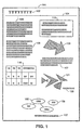
- Figure 1 shows page 101 of a representative document.
- Page 101 is arranged in a two column format and includes title 102, horizontal line 104, several text areas 105, 106 and 107, which include lines of text data, half-tone picture data 108, which includes a graphic image which is non-text, table 110, which includes text information, framed area 116, half-tone picture area 121 accompanied by caption data 126 and picture areas 132 and 135 accompanied by caption data 137.
- a block selection technique attempts to define each area of page 101 in accordance with the type of image data therein. As the block selection technique defines each area, a hierarchical tree structure is created, shown in Figure 2.
- Hierarchical tree structure 200 of Figure 2 contains a plurality of nodes, each of which represents an identified area, or block, of image data.
- Each node of the tree contains feature data which defines the features of its corresponding block of image data.
- the feature data may include block location data, attribute data (specifying image type, such as text, picture, table etc.), sub-attribute data, and child node or parent node pointers.
- Child, or "descendant" nodes represent image data which exist entirely within a larger block of image data.
- a child node is depicted in hierarchical tree structure 200 as a node branching from a parent node.
- the text blocks within frame 116 are depicted in the hierarchical tree structure as nodes 214 and 216, which branch directly from parent node 212, which represents frame 116.
- a node which represents a text block may also contain feature data defining the block's reading orientation and reading order. These data are useful when performing OCR processing on a page's text blocks.
- a method of analysing table-form documents with text attached to the edge of a cell is disclosed in an article by O. Hori: "Table-form structure analysis based on box-driven reasoning", IEICE Trans. Inf. & Syst., volume E79-D, no. 5, 5 June 1996, pages 542-547.
- cells may be separated from text by regarding characters attached to the cell box initially as part of the interior contour of the cell and subsequently separating them from the cell by examining distortions of the boundary lines of the cell box, a character box being created for the separated characters.
- the present invention addresses the foregoing needs by providing a system for identifying and extracting text data which is attached to a frame of a table-cell.
- the present invention provides a method of facilitating extraction of features- in a feature extraction system which analyses image data in an input document and which creates a hierarchical tree structure representative of that document, the method comprising the steps of:
- the present invention provides an apparatus for facilitating extraction of features in a feature extraction system which analyses image data in an input document and which creates a hierarchical tree structure representative of that document, the apparatus comprising:
- One embodiment of this aspect of the invention further comprises recognising a connected component as a text component if 1) a height of the at least one connected component is not less than a third predetermined threshold or a width-to-height ratio of the at least one connected component is not greater than a fourth predetermined threshold, 2) a width of the at least one connected component is not less than a fifth predetermined threshold or a height-to-width ratio of the at least one connected component is not greater than a sixth predetermined threshold, 3) a width or height of the at least one connected component is greater than a seventh predetermined threshold or the at least one text component is between an unattached connected component and another unattached connected component, and 4) a group of connected components comprising the at least one connected component and other connected components in the same row or column meets 1) and 2), and defining a character node of a hierarchical tree structure corresponding to the extended character area and containing both the at least one connected component and any identified unattached connected component.
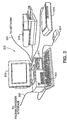
- Figure 3 is a view showing the outward appearance of a representative embodiment of the invention.
- computer system 310 which may be a Macintosh or an IBM PC or PC-compatible system having a windowing environment, such as Microsoft Windows.
- display screen 312 such as a color monitor
- keyboard 313 for entering user commands
- pointing device 314 such as a mouse for pointing to and for manipulating objects displayed on display screen 312.
- Computer system 310 include a mass storage device such as computer disk 311 for storing data files which include document image files, in either compressed or uncompressed format, and for storing application program files which include a block selection application program embodying the present invention. Also stored in disk 311 are various hierarchical tree structure data corresponding to document pages which have been processed according to a block selection technique.
- a multipage document may be input by scanner 316 which scans each page of the document and provides bit-mapped image data of those pages to computer system 310.
- the image data may also be input into computer system 310 from a variety of other sources, such as from a network through network interface 324 or from other sources such as the World Wide Web through facsimile/modem interface 326.
- Printer 318 is provided for outputting processed document images.
- FIG. 4 is a detailed block diagram showing the internal construction of computer system 310.
- computer system 310 includes central processing unit (CPU) 420 which interfaces with computer bus 421.
- CPU central processing unit
- scanner interface 422 printer interface 423, network interface 424, fax/modem interface 426, display interface 427, keyboard interface 428, mouse interface 429, main random access memory (“RAM”) 430, and disk 311.
- printer interface 423 printer interface 423
- network interface 424 printer interface 423
- fax/modem interface 426 printer interface 423
- display interface 427 keyboard interface 428
- mouse interface 429 keyboard interface 428
- main random access memory (“RAM”) 430 main random access memory
- Main memory 430 interfaces with computer bus 421 so as to provide RAM storage to CPU 420 for executing stored process steps such as the process steps of a block selection technique according to the present invention. More specifically, CPU 420 loads process steps from disk 311 into main memory 430 and executes the stored process steps from main memory 430 in order to identify and extract text data which is attached to a table-cell frame in a document image.
- a desktop word-processing program such as WordPerfect for Windows®
- WordPerfect for Windows® may be activated by an operator to create, manipulate and view documents before and after applying a block selection technique to the documents.
- a page analysis program may be executed to perform a block selection technique on a document page and to display the results of the technique to an operator via a windowing environment.
- a document to be analyzed is inserted into scanner 318.
- Scanner 318 creates a bit-mapped image representing the document.
- the image data is stored on disk 311 via computer bus 421 for further processing.
- a block selection application program which contains process steps for executing a block selection technique on the document image data.
- the process steps are stored in main memory 430 and are executed therefrom by CPU 420.
- the process steps of the block selection technique function so as to identify different types of image data within the document image.
- the document page contains a table, such as document page 501 of Figure 5A.
- a block selection technique attempts to identify the image data within a document page by tracing connected components within the page.
- a connected component is a group of black pixels which is completely surrounded by white pixels.
- Figure 5A shows document page 501 containing table 500, 502 and 504, each of which are connected components.
- One technique for tracing connected components is disclosed in aforementioned U.S. Patent No. 5,854,853.
- Tracing is performed by scanning a selected section of image data from the lower right hand portion of the selected section to the left, turning each time a border or previously scanned portion of the desired section is encountered. If a "black" pixel is encountered, adjacent pixels are inspected in order to determine whether any adjacent pixels are also black. If an adjacent black pixel is located, the inspection proceeds from the adjacent black pixel until the exterior contour of the image has been traced. In accordance with the present invention, there is no need to trace the interior portion of a connected component such as picture 504.
- each connected component is rectangularized.
- rectangularization consists of defining the smallest possible rectangular area which completely envelopes a traced connected component.
- rectangles 507, 509 and 510 are drawn around table 500 and pictures 502 and 504.
- the size of each of these rectangles is compared with a threshold size in order to determine whether the circumscribed connected component might be a table. Therefore, because the size of rectangle 507 is greater than the threshold size, table 500 undergoes further processing to determine whether it is a table.
- Table 500 includes several individual table-cells, such as table cells 601 and 602.
- Table-cell 601 contains unattached text 604.
- Table-cell 602 contains unattached text 605, and also contains attached text/data 606 and 607.
- White contours are traced in a manner similar to that described above with respect to connected components, but with white pixels being inspected rather than black pixels.
- the interior of table 500 is scanned for white pixels from the bottom right hand portion to the upper left hand portion.
- adjacent pixels are inspected to determine whether any of the adjacent pixels are also white. Tracing continues until all white contours enclosed by black pixels are traced.
- the white contours of table 500 denoted by reference number 610, are shown in Figure 6.
- the white contours 610 which appear to belong to one cell of table 500 are grouped together.
- white contours within table-cell 602 appear to form a rectangular area and are therefore grouped together.
- a technique for grouping these white contours together is also disclosed in aforementioned U.S. Patent No. 5,848,186.
- These grouped white contours are rectangularized as described above with respect to connected components. However, unlike the rectangularization described above, the rectangularization of these white contours creates a frame outline, which is the smallest rectangle which completely envelopes all traced white contours within a group. After the groups of white contours have been rectangularized, the frequency with which the contours were grouped, known as the group rate, is examined.
- table 500 is determined to be a table.
- a table node of a hierarchical tree structure is created having child nodes corresponding to each cell of table 500.
- Each cell is defined as having an area equal to that circumscribed by a frame outline created by rectangularizing the white contours within the cell.
- the nodes representing each cell of table 500 have a child node representing the white contours within the cell.
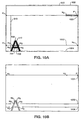
- Figure 7 shows sample table cells and their corresponding white contours and frame outlines.
- Figure 7A shows the interior of an "empty" table-cell 603 after white contour tracing has been performed. As shown, single white contour 610 exists within table-cell 603. It should be noted that white contour 610 lies directly adjacent to each edge of table-cell 603 or in the case that a connected component exists within the cell, adjacent to the connected component itself. Similarly, Figure 7B shows traced white contour 610 within table-cell 601 containing unattached connected components 604.
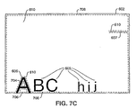
- Figure 7C shows traced white contours 610, 704 and 706 within table-cell 602 containing both attached connected components 606 and 607 and unattached connected components 605.
- the above-described method of tracing results in white contours which circumscribe an exclusive area. As a result, after tracing, no white contours exist within another white contour.
- the connected components within each white contour are traced as described above in order to rectangularize and identify any unattached connected components within each cell.
- the hierarchical tree structure is updated with nodes representing the unattached connected components.
- the present invention is unable to trace and identify an attached connected component such as component 606 of table-cell 602, as shown in Figure 7C.
- the above-described method of contour tracing is unable to trace the side of attached component 606 which is attached to table-cell 602. Since attached connected component 606 cannot be properly traced, it is not rectangularized and therefore not subsequently identified and represented by a node.
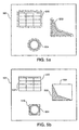
- an initial rectangular area is defined. For example, no unattached connected components are located within table-cell 603, therefore the initial rectangular area is defined as shown in Figure 8A.
- initial rectangular area 801 is defined as a rectangle having left and right sides both located at the horizontal midpoint of frame outline 708 and extending from one pixel below the top of frame outline 708 to one pixel above the bottom of frame outline 708.
- unattached connected components exist within a table-cell
- identified unattached connected components are rectangularized as described above with respect to frame outline 708, thereby creating a rectangle which circumscribes all unattached connected components.
- each of the letters "ABC hij" in table-cell 602 touches the table-cell 602.
- the area of circumscribing rectangle 802 is then compared to a threshold value X2. If the area is less than X2, each side of circumscribing rectangle 802 is extended until it reaches a row or column containing a black pixel. The sides can be extended one at a time or simultaneously. If no black pixel has been encountered by the time the side is a specified distance from frame outline 708, the side remains at its original position, as shown in Figure 8B.
- the initial rectangular area is defined as resulting rectangle 804.
- the initial rectangular area is defined as circumscribing rectangular area 805, shown in Figure 8C.
- the area is extended to include any attached connected components located within table-cell 602.
- a detection area is defined as the entire row or column directly adjacent to one side of the initial rectangular area. For example, as shown in Figure 9A, detection area 901 adjacent to initial rectangular area 805 is defined.
- each pixel in the detection area is examined. If any black pixels exist in the detection area, initial rectangular area 805 is extended to include detection area 901. As shown in Figure 9B, due to attached connected component 606, the left side of initial rectangular area 805 has been extended to include detection area 901.
- the detection area is redefined.
- the detection area is redefined to be group of pixels 902 adjacent to the previous detection area toward boundary 978 of frame outline 708 described above, as shown in Figure 9C. The process then continues as described above.
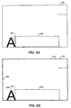
- FIG. 9D shows table-cell 602 and extended character area 910 after the above extension process has been completed.
- the initial rectangular area now includes any black pixels located within frame outline 708, including those black pixels which are on the boundary of frame outline 708. Furthermore, by virtue of this process, extended rectangular area 910 is the smallest rectangle which contains all of the attached and unattached connected components located within table-cell 602.
- Extended rectangular area 910 and the white contours within table-cell 602 are used to combine groups of black pixels inside extended text area 910. The black pixels are combined in order to extract any attached connected components.
- first row 1001 of extended character area 910 is selected. Any boundary pixels located in selected row 1001 are identified. Boundary pixels are all pixels of a particular row which are on the boundary of a selected white contour. For example, pixels w1, w2, w3, and w4 of row 1002 are boundary pixels.
- the identified boundary pixels are numbered sequentially from the left end of table-cell 602. In the case that each white contour has been analyzed with respect to the currently selected row, the next row is analyzed. If not, another white contour is selected. In the case that boundary pixels of more than one white contour are located on a single row, the boundary pixels are numbered sequentially from the last number assigned to a boundary pixel in that row. For example, in the case of row 1002, boundary pixels w1, w2, w3 and w4 are identified during the analysis of white contour 704. Thereafter, two boundary pixels are identified corresponding to white contour 704. These boundary pixels are numbered w5 and w6, respectively. It should be noted that this numbering scheme applies only to boundary pixels located in a single row, and that boundary pixel numbering resets to w1 each time a new row is analyzed.
- Black boundary pixels are black pixels of the selected row which are located on the extended rectangular area 910. For example, when row 1001 is selected, black pixel P is identified.
- black pixels which lie between even and odd-numbered boundary pixels of a single row are detected. For example, as shown in Figure 10B, black pixels are detected in row 1002 between boundary pixels w2 and w5 and between boundary pixels w6 and w3. In addition, in row 1008, black pixels between boundary pixels w2 and w3 are detected. Black pixels are detected in this manner for each row of the extended character area 910.
- the present invention detects black pixels lying between an even-numbered boundary pixel and a black boundary pixel. For example, the black pixels lying between pixel w2 of row 1001 and black boundary pixel P are detected. Similarly, black pixels lying between a black boundary pixel and an odd-numbered boundary pixel are detected.
- Each detected black pixel is grouped together to form attached connected components.
- FIG 10B adjacent black pixels are grouped together in order to form the attached connected component "A".
- a formed attached connected component is examined to determine whether it is a horizontal line. Accordingly, if the height of the component is less than a predetermined threshold X4 and if the width-to-height ratio of the component is greater than a predetermined threshold X5, the component is designated a horizontal line.
- the component is designated a vertical line.
- the component is designated as part of table-cell 502.
- the component is analyzed to determine if any other components are located in its row or column. If so, the column or row of components is examined as described above with respect to horizontal and vertical lines. If the row or column of components meet the criteria of either a vertical or horizontal line, the components are designated as a broken line.
- the attached connected component is assumed to be a text component. Accordingly, a node is created representing attached text 606.
- the text within table-cell 602 can be automatically processed in accordance with an OCR system. Thereafter, utilizing keyboard 313 and mouse 314, the text can be further processed with a word-processing application stored on disk 311 and the entire document image can be output using printer 318.
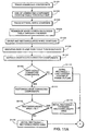
- step S1101 the connected components of a document image are traced.
- the exterior black pixels of table 500 are traced.
- the result of the tracing is used in step S1102 to determine if the size of the traced component is equal to or greater than a predetermined threshold which would indicate that the traced component could be a table.
- the size of table 500 is greater than the predetermined threshold so identification of the image proceeds to step S1103, at which point the white contours 610 within table 500 are traced.
- step S1104 if the number of white contours within a traced connected component is less than a predetermined number, the connected component is not a table. However, because the number of white contours 610 in table 500 is greater than the predetermined number, flow continues from step S1104 to step S1105 in order to determine whether table 500 is a table.
- step S1105 the white contours are grouped and rectangularized to form frame outlines, which are shown in Figure 7 and denoted by reference number 708.
- step S1606 if the frequency with which the white contours are grouped is less than a predetermined rate, the connected component containing the white contours is determined to be a table. In the case of table 500, table 500 is determined to be a table because the grouping rate of the white contours 610 of table 500 is small. Flow then proceeds to step S1107.
- step S1107 unattached connected components within the white contours of each cell of table 500 are traced. Once these components are traced, nodes representing the components are created and placed in a hierarchical tree structure so as to descend from a node representing the white contours which contain the unattached connected components. At this point, the hierarchical tree structure does not contain any nodes which represent attached connected components within table 500.
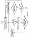
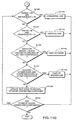
- step S1109 if no unattached connected components exist, flow proceeds to step S1110 at which point the initial rectangular area is defined as shown in Figure 8A.
- step S1111 the unattached connected components are rectangularized to form a circumscribing rectangle, such as rectangles 802 and 805 of Figures 8B and 8C. Thereafter, the area of the circumscribing rectangle is compared to a threshold value X2 in step S1112.
- step S1114 If the area of a circumscribing rectangle is less than X2, as in the case of rectangle 802 of Figure 8B, flow proceeds to step S1114 at which point each side of circumscribing rectangle 802 is extended until it reaches a row or column containing a black pixel. If no black pixel has been encountered by the time the side is a specified distance from frame outline 708, the side remains at its original position and the initial rectangular area is defined as resulting rectangle 804.
- step S1115 In the case that the area of a circumscribing rectangle is greater than a predetermined threshold value X2, as in the case of rectangle 805, flow proceeds to step S1115, wherein the initial rectangular area is defined as circumscribing rectangle 805.
- the initial rectangular area defined according to the above steps is used to create an extended rectangular area which circumscribes the unattached and the attached connected components within the frame.
- a detection area is defined as the entire row or column directly adjacent to one side of the initial rectangular area.
- Figure 9A shows detection area 901 adjacent to initial rectangular area 805.
- step S1117 The pixels within detection area 901 are examined in step S1117. If any black pixels exist in the detection area, flow proceeds to step S1119, at which point initial rectangular area 805 is extended to include detection area 901. For example, due to attached connected component 606, the left side of initial rectangular area 805 has been extended in Figure 9B to include detection area 901.
- step S1120 detection area 901 is examined to determine whether any pixels in detection area 901 are also on boundary 978 of frame outline 708 lying opposite from initial rectangular area 805. If so, flow proceeds to step S1124. If not, flow proceeds to step S1121 where the detection area is redefined to be the group of pixels 902 adjacent to the previous detection area toward boundary 978 of frame outline 708, as shown in Figure 9C. Flow then proceeds to step S1117 and continues as described above.
- step S1117 flow proceeds to step S1122, at which point the distance between the detection area and boundary 978 of frame outline 708 which lies opposite from initial rectangular area 805 is compared with a predetermined distance X3. If the distance is greater than X3, flow proceeds to step S1123.
- step S1123 the detection area is redefined as described above with respect to step S1121. Flow returns to step S1117, and continues as described above.
- step S1122 If, in step S1122, the distance is less than or equal to distance X3, it is assumed that no connected components are attached to this side of table-cell 502 and flow proceeds to step S1124.
- step S1116 In the case that pixels adjacent to each of the four sides of the initial rectangular area 805 have not been examined, flow reverts to step S1116, where a new detection area is defined as a row or column of pixels directly adjacent to another side of original initial rectangular area 805. If not, flow then proceeds from step S1124 to step S1125. At this point, initial rectangular area 805 has been extended to include all attached connected components within table-cell 502, as shown in Figure 9D.
- the first row 1001 of extended character area 910 is selected for analysis in step S1126. Then, in step S1127, a white contour within the frame outline 708 is selected for analysis. In step S1129, boundary pixels located in the selected row 1001 are identified. Boundary pixels are all pixels of a particular row which are on the boundary of a selected white contour. For example, pixels w1, w2, w3, and w4 of row 1002 are boundary pixels.
- step S1130 the identified boundary pixels are numbered sequentially from the left end of table-cell 502.
- step S1131 in the case that each white contour has been analyzed with respect to the currently selected row, flow proceeds to step S1134. If not, flow proceeds to step S1132, in which another white contour is selected. Flow then returns to step S1129, which operates as described above.
- step S1130 is repeated during the analysis of a single row, any identified boundary pixels are numbered sequentially from the last number assigned to a boundary pixel in that row. For example, in the case of row 1002, boundary pixels w1, w2, w3 and w4 are identified during the analysis of white contour 610. Thereafter, two boundary pixels are identified corresponding to white contour 704. These boundary pixels are numbered w5 and w6, respectively.
- step S1134 is executed if all white contours have been analyzed with respect to a single row.
- black boundary pixels are identified, which comprise black pixels of the selected row which are located on the extended rectangular area 910. For example, when row 1006 is selected, black pixel P is identified.
- step S1135 If all the rows of extended rectangular area 910 have not been analyzed, flow proceeds from step S1135 to S1136, in which the next row of extended rectangular area 910 is selected and flow returns to step S1127. On the other hand, if, in step S1135, the last row analyzed was the bottom row 1004 of extended rectangular area 910, flow proceeds to step S1137, and the boundary pixels of each row are analyzed. Specifically, black pixels which lie between even and odd-numbered boundary pixels of a single row are detected. As shown in Figure 10B, black pixels are detected in row 1002 between boundary pixels w2 and w5 and between boundary pixels w6 and w3. In addition, in row 1006, black pixels between boundary pixels w2 and w3 are detected. Black pixels are detected in this manner for each row of extended rectangular area 910.
- step S11308 black pixels lying between an even-numbered boundary pixel and a black boundary pixel are detected. For example, the black pixels lying between pixel w2 of row 1001 and black boundary pixel P are detected. Similarly, in step S1138, any black pixels lying between a black boundary pixel and an odd-numbered boundary pixel are detected.
- step S1139. All adjacent black pixels detected in steps S1137 and S1138 are grouped together to form attached connected components in step S1139. For example, in Figure 10B, adjacent black pixels are grouped together in order to form the attached connected component "A". Once each black pixel of each attached connected component is grouped, the attached connected components formed in step S1139 are examined to determine whether they are text components.
- step S1140 an attached connected component is examined to determine whether it is a horizontal line. Accordingly, if the height of the component is less than a predetermined threshold X4 and if the width-to-height ratio of the component is greater than a predetermined threshold X5, flow proceeds to step S1141, at which point the component is designated a horizontal line, and flow proceeds to step S1150.
- step S1142 in which the attached connected component is examined to determine whether it is a vertical line. Accordingly, if the width of the component is less than a predetermined threshold X6 and the height-to-width ratio of the component is greater than a predetermined threshold X7, flow proceeds to step S1144. In step S1144, the component is designated a vertical line and flow proceeds to step S1150.
- Step S1145 determines whether the component is part of table-cell 502. Therefore, in step S1145, if the height or width of the component is less than a predetermined threshold X8 and the component is also entirely above, below or to either side of all text connected components within the frame, flow proceeds to step S1146, at which point the component is designated as part of the table-cell 502 and flow continues to step S1150.
- step S1147 the component is analyzed to determine if any other components are located in its row or column. If so, the column or row of components is examined as described above with respect to horizontal and vertical lines. If the row or column of components meet the criteria of either a vertical or horizontal line, the component is designated as part of a broken line in step S1148. Flow then proceeds to step S1120.
- step S1149 the attached connected component is assumed to be a text component. Accordingly, a node is created representing unattached text 606.
- step S1150 Flow then proceeds to step S1150, from which, if any attached connected components within table-cell 502 have not yet been analyzed, flow returns to step S1140. If all attached connected components have been analyzed, the flow of the present invention terminates.
- the present invention may be incorporated into any page analysis system and is not limited to the block selection techniques described above. Furthermore, the present invention may be used to identify and extract text data attached to any circumscribing frame, regardless of whether the frame represents a cell of a table, a decorative border, etc.
- a rectangular or similar area is identified according to predetermined rules.
- the area is extended according to further rules, so as to encompass one or more objects initially attached to the table cell or other frame, but which are judged according to said further criteria to comprise further text elements related to those within the initially area.
Landscapes
- Engineering & Computer Science (AREA)
- Computer Vision & Pattern Recognition (AREA)
- Physics & Mathematics (AREA)
- General Physics & Mathematics (AREA)
- Multimedia (AREA)
- Theoretical Computer Science (AREA)
- Artificial Intelligence (AREA)
- Character Input (AREA)
- Image Analysis (AREA)
- Processing Or Creating Images (AREA)
Applications Claiming Priority (2)
| Application Number | Priority Date | Filing Date | Title |
|---|---|---|---|
| US08/664,675 US6157738A (en) | 1996-06-17 | 1996-06-17 | System for extracting attached text |
| US664675 | 1996-06-17 |
Publications (3)
| Publication Number | Publication Date |
|---|---|
| EP0814422A2 EP0814422A2 (en) | 1997-12-29 |
| EP0814422A3 EP0814422A3 (en) | 1998-01-28 |
| EP0814422B1 true EP0814422B1 (en) | 2003-01-08 |
Family
ID=24666972
Family Applications (1)
| Application Number | Title | Priority Date | Filing Date |
|---|---|---|---|
| EP97304087A Expired - Lifetime EP0814422B1 (en) | 1996-06-17 | 1997-06-11 | System for extracting attached text from a table-cell frame |
Country Status (4)
| Country | Link |
|---|---|
| US (1) | US6157738A (enExample) |
| EP (1) | EP0814422B1 (enExample) |
| JP (1) | JP4077904B2 (enExample) |
| DE (1) | DE69718243T2 (enExample) |
Cited By (1)
| Publication number | Priority date | Publication date | Assignee | Title |
|---|---|---|---|---|
| CN104268545A (zh) * | 2014-09-15 | 2015-01-07 | 同方知网(北京)技术有限公司 | 一种电子档版式文件中的表格区域识别与内容栅格化方法 |
Families Citing this family (17)
| Publication number | Priority date | Publication date | Assignee | Title |
|---|---|---|---|---|
| US6112216A (en) * | 1997-12-19 | 2000-08-29 | Microsoft Corporation | Method and system for editing a table in a document |
| AU4077300A (en) * | 1999-04-07 | 2000-10-23 | Raf Technology, Inc. | Extracting user data from a scanned image of a pre-printed form |
| JP3204259B2 (ja) * | 1999-10-06 | 2001-09-04 | インターナショナル・ビジネス・マシーンズ・コーポレーション | 文字列抽出方法、手書き文字列抽出方法、文字列抽出装置、および画像処理装置 |
| JP3425408B2 (ja) * | 2000-05-31 | 2003-07-14 | 株式会社東芝 | 文書読取装置 |
| EP1271403B1 (en) * | 2001-06-26 | 2005-03-09 | Nokia Corporation | Method and device for character location in images from digital camera |
| JP2004088585A (ja) * | 2002-08-28 | 2004-03-18 | Fuji Xerox Co Ltd | 画像処理システムおよびその方法 |
| JP4897520B2 (ja) | 2006-03-20 | 2012-03-14 | 株式会社リコー | 情報配信システム |
| US20070253615A1 (en) * | 2006-04-26 | 2007-11-01 | Yuan-Hsiang Chang | Method and system for banknote recognition |
| US8331680B2 (en) * | 2008-06-23 | 2012-12-11 | International Business Machines Corporation | Method of gray-level optical segmentation and isolation using incremental connected components |
| CN102314608A (zh) * | 2010-06-30 | 2012-01-11 | 汉王科技股份有限公司 | 文字图像中行提取的方法和装置 |
| US20130163871A1 (en) * | 2011-12-22 | 2013-06-27 | General Electric Company | System and method for segmenting image data to identify a character-of-interest |
| US9842281B2 (en) * | 2014-06-05 | 2017-12-12 | Xerox Corporation | System for automated text and halftone segmentation |
| US20160055376A1 (en) * | 2014-06-21 | 2016-02-25 | iQG DBA iQGATEWAY LLC | Method and system for identification and extraction of data from structured documents |
| JP6173542B1 (ja) * | 2016-08-10 | 2017-08-02 | 株式会社Pfu | 画像処理装置、画像処理方法、および、プログラム |
| CN115240214A (zh) * | 2021-04-09 | 2022-10-25 | 华南理工大学广州学院 | 一种表格结构识别方法 |
| CN113221778B (zh) * | 2021-05-19 | 2022-05-10 | 北京航空航天大学杭州创新研究院 | 手写表格的检测与识别方法及装置 |
| CN113901950A (zh) * | 2021-11-05 | 2022-01-07 | 上海派拉软件股份有限公司 | 一种高准确率的表格ocr识别方法及系统 |
Family Cites Families (4)
| Publication number | Priority date | Publication date | Assignee | Title |
|---|---|---|---|---|
| US4377803A (en) * | 1980-07-02 | 1983-03-22 | International Business Machines Corporation | Algorithm for the segmentation of printed fixed pitch documents |
| JPS63268081A (ja) * | 1987-04-17 | 1988-11-04 | インタ−ナショナル・ビジネス・マシ−ンズ・コ−ポレ−ション | 文書の文字を認識する方法及び装置 |
| US5588072A (en) * | 1993-12-22 | 1996-12-24 | Canon Kabushiki Kaisha | Method and apparatus for selecting blocks of image data from image data having both horizontally- and vertically-oriented blocks |
| US5848186A (en) * | 1995-08-11 | 1998-12-08 | Canon Kabushiki Kaisha | Feature extraction system for identifying text within a table image |
-
1996
- 1996-06-17 US US08/664,675 patent/US6157738A/en not_active Expired - Lifetime
-
1997
- 1997-06-11 DE DE69718243T patent/DE69718243T2/de not_active Expired - Lifetime
- 1997-06-11 EP EP97304087A patent/EP0814422B1/en not_active Expired - Lifetime
- 1997-06-17 JP JP16020597A patent/JP4077904B2/ja not_active Expired - Fee Related
Cited By (1)
| Publication number | Priority date | Publication date | Assignee | Title |
|---|---|---|---|---|
| CN104268545A (zh) * | 2014-09-15 | 2015-01-07 | 同方知网(北京)技术有限公司 | 一种电子档版式文件中的表格区域识别与内容栅格化方法 |
Also Published As
| Publication number | Publication date |
|---|---|
| DE69718243T2 (de) | 2003-08-28 |
| US6157738A (en) | 2000-12-05 |
| EP0814422A2 (en) | 1997-12-29 |
| EP0814422A3 (en) | 1998-01-28 |
| JPH1083431A (ja) | 1998-03-31 |
| DE69718243D1 (de) | 2003-02-13 |
| JP4077904B2 (ja) | 2008-04-23 |
Similar Documents
| Publication | Publication Date | Title |
|---|---|---|
| EP0814422B1 (en) | System for extracting attached text from a table-cell frame | |
| EP0758775B1 (en) | Feature extraction system | |
| US5774579A (en) | Block selection system in which overlapping blocks are decomposed | |
| CN114004204B (zh) | 基于计算机视觉的表格结构重建与文字提取方法和系统 | |
| US6115497A (en) | Method and apparatus for character recognition | |
| US6512848B2 (en) | Page analysis system | |
| US5893127A (en) | Generator for document with HTML tagged table having data elements which preserve layout relationships of information in bitmap image of original document | |
| KR100251600B1 (ko) | 이미지 처리 방법 및 디지탈 컴퓨터 | |
| US6903751B2 (en) | System and method for editing electronic images | |
| EP0660256B1 (en) | Method and apparatus for selecting text and/or non-text blocks in a stored document | |
| US5619594A (en) | Image processing system with on-the-fly JPEG compression | |
| US6711292B2 (en) | Block selection of table features | |
| EP0690415B1 (en) | Editing scanned document images using simple interpretations | |
| EP0753833A1 (en) | Apparatus and method for extracting articles from a document | |
| Hori et al. | Robust table-form structure analysis based on box-driven reasoning | |
| JPH0668300A (ja) | 文書画像のレイアウトモデルを作成する方法及び装置 | |
| EP0768000B1 (en) | Automatic determination of blank pages and bounding boxes for binary images | |
| EP0712089B1 (en) | Document analyzer application programming interface | |
| JP2890306B2 (ja) | 表領域分離装置および表領域分離方法 | |
| JPH0697470B2 (ja) | 文字列抽出装置 | |
| JPH0743718B2 (ja) | マルチメディア文書構造化方式 | |
| JPH07296109A (ja) | 画像処理方法とその装置 | |
| JPH05342325A (ja) | 文書処理装置およびその装置のためのフォーム登録装置 |
Legal Events
| Date | Code | Title | Description |
|---|---|---|---|
| PUAI | Public reference made under article 153(3) epc to a published international application that has entered the european phase |
Free format text: ORIGINAL CODE: 0009012 |
|
| PUAL | Search report despatched |
Free format text: ORIGINAL CODE: 0009013 |
|
| AK | Designated contracting states |
Kind code of ref document: A2 Designated state(s): AT BE CH DE DK ES FI FR GB GR IE IT LI LU MC NL PT SE |
|
| AX | Request for extension of the european patent |
Free format text: AL;LT;LV;RO;SI |
|
| AK | Designated contracting states |
Kind code of ref document: A3 Designated state(s): AT BE CH DE DK ES FI FR GB GR IE IT LI LU MC NL PT SE |
|
| AX | Request for extension of the european patent |
Free format text: AL;LT;LV;RO;SI |
|
| RHK1 | Main classification (correction) |
Ipc: G06K 9/34 |
|
| 17P | Request for examination filed |
Effective date: 19980612 |
|
| RBV | Designated contracting states (corrected) |
Designated state(s): DE FR GB IT |
|
| 17Q | First examination report despatched |
Effective date: 20010209 |
|
| GRAG | Despatch of communication of intention to grant |
Free format text: ORIGINAL CODE: EPIDOS AGRA |
|
| GRAG | Despatch of communication of intention to grant |
Free format text: ORIGINAL CODE: EPIDOS AGRA |
|
| GRAH | Despatch of communication of intention to grant a patent |
Free format text: ORIGINAL CODE: EPIDOS IGRA |
|
| GRAH | Despatch of communication of intention to grant a patent |
Free format text: ORIGINAL CODE: EPIDOS IGRA |
|
| GRAA | (expected) grant |
Free format text: ORIGINAL CODE: 0009210 |
|
| AK | Designated contracting states |
Kind code of ref document: B1 Designated state(s): DE FR GB IT |
|
| PG25 | Lapsed in a contracting state [announced via postgrant information from national office to epo] |
Ref country code: IT Free format text: LAPSE BECAUSE OF FAILURE TO SUBMIT A TRANSLATION OF THE DESCRIPTION OR TO PAY THE FEE WITHIN THE PRESCRIBED TIME-LIMIT;WARNING: LAPSES OF ITALIAN PATENTS WITH EFFECTIVE DATE BEFORE 2007 MAY HAVE OCCURRED AT ANY TIME BEFORE 2007. THE CORRECT EFFECTIVE DATE MAY BE DIFFERENT FROM THE ONE RECORDED. Effective date: 20030108 Ref country code: FR Free format text: LAPSE BECAUSE OF FAILURE TO SUBMIT A TRANSLATION OF THE DESCRIPTION OR TO PAY THE FEE WITHIN THE PRESCRIBED TIME-LIMIT Effective date: 20030108 |
|
| REG | Reference to a national code |
Ref country code: GB Ref legal event code: FG4D |
|
| REF | Corresponds to: |
Ref document number: 69718243 Country of ref document: DE Date of ref document: 20030213 Kind code of ref document: P |
|
| PLBE | No opposition filed within time limit |
Free format text: ORIGINAL CODE: 0009261 |
|
| STAA | Information on the status of an ep patent application or granted ep patent |
Free format text: STATUS: NO OPPOSITION FILED WITHIN TIME LIMIT |
|
| EN | Fr: translation not filed | ||
| 26N | No opposition filed |
Effective date: 20031009 |
|
| PGFP | Annual fee paid to national office [announced via postgrant information from national office to epo] |
Ref country code: GB Payment date: 20150626 Year of fee payment: 19 |
|
| PGFP | Annual fee paid to national office [announced via postgrant information from national office to epo] |
Ref country code: DE Payment date: 20160630 Year of fee payment: 20 |
|
| GBPC | Gb: european patent ceased through non-payment of renewal fee |
Effective date: 20160611 |
|
| PG25 | Lapsed in a contracting state [announced via postgrant information from national office to epo] |
Ref country code: GB Free format text: LAPSE BECAUSE OF NON-PAYMENT OF DUE FEES Effective date: 20160611 |
|
| REG | Reference to a national code |
Ref country code: DE Ref legal event code: R071 Ref document number: 69718243 Country of ref document: DE |