EP0813219A1 - Undervoltage release device - Google Patents
Undervoltage release device Download PDFInfo
- Publication number
- EP0813219A1 EP0813219A1 EP96109274A EP96109274A EP0813219A1 EP 0813219 A1 EP0813219 A1 EP 0813219A1 EP 96109274 A EP96109274 A EP 96109274A EP 96109274 A EP96109274 A EP 96109274A EP 0813219 A1 EP0813219 A1 EP 0813219A1
- Authority
- EP
- European Patent Office
- Prior art keywords
- pawl
- switch
- auxiliary switch
- armature
- point
- Prior art date
- Legal status (The legal status is an assumption and is not a legal conclusion. Google has not performed a legal analysis and makes no representation as to the accuracy of the status listed.)
- Granted
Links
Images


Classifications
-
- H—ELECTRICITY
- H01—ELECTRIC ELEMENTS
- H01H—ELECTRIC SWITCHES; RELAYS; SELECTORS; EMERGENCY PROTECTIVE DEVICES
- H01H83/00—Protective switches, e.g. circuit-breaking switches, or protective relays operated by abnormal electrical conditions otherwise than solely by excess current
- H01H83/12—Protective switches, e.g. circuit-breaking switches, or protective relays operated by abnormal electrical conditions otherwise than solely by excess current operated by voltage falling below a predetermined value, e.g. for no-volt protection
-
- H—ELECTRICITY
- H01—ELECTRIC ELEMENTS
- H01H—ELECTRIC SWITCHES; RELAYS; SELECTORS; EMERGENCY PROTECTIVE DEVICES
- H01H71/00—Details of the protective switches or relays covered by groups H01H73/00 - H01H83/00
- H01H71/02—Housings; Casings; Bases; Mountings
- H01H71/0264—Mountings or coverplates for complete assembled circuit breakers, e.g. snap mounting in panel
- H01H71/0271—Mounting several complete assembled circuit breakers together
- H01H2071/0278—Mounting several complete assembled circuit breakers together with at least one of juxtaposed casings dedicated to an auxiliary device, e.g. for undervoltage or shunt trip
-
- H—ELECTRICITY
- H01—ELECTRIC ELEMENTS
- H01H—ELECTRIC SWITCHES; RELAYS; SELECTORS; EMERGENCY PROTECTIVE DEVICES
- H01H83/00—Protective switches, e.g. circuit-breaking switches, or protective relays operated by abnormal electrical conditions otherwise than solely by excess current
- H01H83/20—Protective switches, e.g. circuit-breaking switches, or protective relays operated by abnormal electrical conditions otherwise than solely by excess current operated by excess current as well as by some other abnormal electrical condition
- H01H2083/208—Converting under voltage release [UVR] and shunt release
-
- H—ELECTRICITY
- H01—ELECTRIC ELEMENTS
- H01H—ELECTRIC SWITCHES; RELAYS; SELECTORS; EMERGENCY PROTECTIVE DEVICES
- H01H71/00—Details of the protective switches or relays covered by groups H01H73/00 - H01H83/00
- H01H71/10—Operating or release mechanisms
- H01H71/12—Automatic release mechanisms with or without manual release
- H01H71/46—Automatic release mechanisms with or without manual release having means for operating auxiliary contacts additional to the main contacts
- H01H71/465—Self-contained, easily replaceable microswitches
Definitions
- the invention relates to an undervoltage release, in particular can be coupled to low-voltage circuit breakers, the electromagnetic release device of which acts on an unlatching device with an armature falling under undervoltage, the armature of which is applied to the magnet system of the release device by means of a manual control element and a holding lever when switched on, specifically according to the generic term of claim 1.
- the holding lever holds the armature at least close to the poles of the magnet system until voltage is applied to the armature by switching on by means of an auxiliary switch, which voltage can hold the armature under normal conditions.
- This switch-on takes place prematurely with respect to an imaginary system switch-on position, which is predetermined, for example, by circuit breakers to be coupled.
- undervoltage release DE-C-31 14 7157
- the structure is to be simplified; he works with a pressure lever and a ratchet lever with a common axis.
- a third axis is introduced in another undervoltage release (EP-A-0 331 586) with an essentially three-part kinematics of ratchet lever, release lever and intermediate lever compared to the aforementioned release.
- the object of the invention is to create an undervoltage release with simple and clear components develop that can be easily adapted to the most diverse requirements.
- an undervoltage release according to claim 1.
- the holding lever is then guided from a link coupled to the manual control element to the armature bearing against the magnet system, the link subsequently having a release area kinematically.
- the pawl of the unlatching device is shaped and or or so positioned with respect to the auxiliary switch and its structure that an action point is formed for actuating the auxiliary switch, with at least one contact path of the auxiliary switch being closed around the winding of the magnet system in the switched-on position of the undervoltage release to put on tension.
- the release area of the pawl eliminates, for example in comparison to an undervoltage release according to DE-C-33 08 437, an additional energy store in the magnet system which has to be tensioned by pressing it down in order to release the armature of the magnet system for release.
- Due to the shape of the pawl, which forms an action point for actuating the auxiliary switch commercially available auxiliary switches can be used and arranged as components in a suitable manner.
- auxiliary switch is provided with two electrically parallel switching paths on a carrier according to claim 3, one achieves a simple and independent adjustment option from the rest of the system.
- undervoltage release according to claim 4 is provided with six connections, two for the magnet system Tripping device and four for the auxiliary switch, a high operating voltage can be supplied to the auxiliary switch on the input side, which is reduced on the output side by a control transformer for the coil of the magnet system, as illustrated in FIG. 11.
- the structure of an undervoltage release according to the invention makes it possible to derive a shunt release with fewer, and otherwise with the same components.
- the system for the adjustment arm of the auxiliary switch can be adjusted by a structure according to claim 7 and thus adjusted.
- the undervoltage release can work according to claim 8 with an auxiliary switch, the switching paths are designed on the principle of a snap switch.
- the point of action from the pawl on the auxiliary switch is designed as a plunger, the penetration depth of which controls the position of the snap switches.
- the backdrop for the holding lever can be designed according to claim 9 in the manual control element in a roller body with the bearing point of the manual control element, in which an arch web is formed along a sector on the roller body.
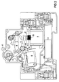
- the undervoltage release according to FIG. 1 has an electromagnetic release device 1 with an armature 2, which drops out of the magnet system in the event of undervoltage and acts on an unlatching device 3.
- the armature 2 is applied by means of a manual control element 4 and a holding lever 5 when switched on to the magnet system of the release device 1 until the armature 2 holding voltage is applied to the magnet system by switching on by means of an auxiliary switch 6.
- the voltage leads in relation to an imaginary system switch-on position, as it is given by devices to be monitored or laterally installed circuit breakers. Applying the armature 2 is understood to mean that it is brought close to the magnet system up to permitted tolerances.
- the holding lever 5 is guided with the manual control member 4 through a link 7 until the armature rests on the magnet system, the link subsequently having a release area 8 kinematically.
- the pawl 9 is shaped and / or positioned with respect to the auxiliary switch 6 and its structure in such a way that an action point 10 for actuating the auxiliary switch 6 is formed. In the switched-on position of the undervoltage release, at least one contact path of the auxiliary switch 6 is thereby closed.
- the link 7 for the holding lever 5 is embodied in the manual control element 4 in a roller body with the bearing point 11 of the manual control element as an arc web along a sector of the roller body.
- the holding lever 5 is held here by an arm engaging behind the arch web as an engagement body 12 of the link guide in its contact position for applying the armature 2 until the release area 8 is reached when the manual control element 4 is turned further.
- the pawl 9 finds a latching point on the coupling member 15, on which the holding lever 5 can rotate the coupling member 15 and thus unlatch when the armature 2 drops into the switching position according to FIG. 4.
- the pawl 9 is rotatable in a guided, movable bearing 16 and connected to the manual control member 4 by the bracket 17.
- the pawl 9 can act with an integrally formed engaging body 18 on an arm 19 of the driver 14 and twist it, as a result of which devices, for example line circuit breakers, can be triggered.
- the auxiliary switch 9 with, for example, two electrically parallel switching paths is arranged on a carrier 13, which can be pivoted about a bearing point 20 of the carrier, at least for adjustment under the action of the pawl, until the carrier 13 rests with its adjusting arm 21 on an adjustable adjusting system 22.
- This adjustment system can be formed by a screw, in particular a grub screw. This can be made self-tapping in a housing gap.
- the auxiliary switch 6 can be designed with switching paths based on the principle of a snap switch, the point of action of which from the pawl is designed as a plunger 23, the penetration depth of which controls the position of the snap switch.
- the holding lever 5 has a fixed pivot bearing 24.
- An arm 25 of the pawl 9 can act on the holding lever 5.
- the pawl 9 is acted upon by an energy accumulator 26 which is in the essentially forms the energy store of the undervoltage release.
- the undervoltage release has electrical connections 27 to 32 in and behind the plane of the drawing, ie a total of six connections.
- two connections, 27, behind the drawing plane, and 28, behind the drawing plane are provided for the magnet system of the release device 1.
- the connections 29 and 30 are electrically connected to a switching path of the auxiliary switch 6 and the connections 31 and 32 to a second switching path of the auxiliary switch 6.
- an electrical circuit 33 is switched on, which rectifies the voltage and, if necessary, prepares it or converts it to other values.
- This circuit 33 is designed, for example, as a flat module.
- the switching paths of the auxiliary switch 6 are closed as long as the plunger 23 of the auxiliary switch 6 is pressed in by the point of action 10 of the pawl 9.
- the pawl 9 presses in the plunger 23, so that the switching paths in the auxiliary switch 6 are closed.
- the holding lever 5 is released by the manual control element 4 and is under the force of a weak spring 34 on the magnet system of the release device 1, the armature 2 being held against the force of a release spring 35 by electromagnetic forces.
- the holding lever 5 is already released from the link 7 at a grip position of approximately 60 ° of the manual control element 4, seen in the switch-on position, and is in contact with the armature 2 in the auxiliary switch 6 when the switching paths are closed.
- the armature is already held by electromagnetic forces. This switching position is shown in FIG 3. If an undervoltage already occurs when switching on according to FIG.
- the armature 2 drops out, as shown in FIG. 4.
- the coupling member 15 is rotated clockwise, so that in the unlatching device 3, the latching point is released and the pawl 9 acts with its engaging body 18 on the driver 14 and rotates it counterclockwise under the force of the pawl spring 26, according to FIG. 5 the magnet system of the release device 1 already being returned to the switched-on position by applying the Anchor 2 is transferred.
- the pawl 9 lifts the holding lever 5 into this position by the pawl arm 25.
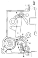
- the undervoltage release according to FIG. 1 enables the derivation of a shunt release according to FIG. 6, in which the holding lever is removed and the magnet system of the release device 1 is mounted upside down.
- the magnet system and the unlatching device 3 are matched to the fact that they are without a holding lever in the area of action of a plunger 36 of the magnetic release of the release device 1 with the armature 2 attracted as a result of a working current.
- the other components of the undervoltage release can be used. It can serve as a remote switch for remote tripping with the driver 14 coupled side circuit breaker.
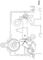
- FIGS. 7 to 9 A control of the torque exerted by the energy accumulator 26 of the pawl at different grip positions of the manual control element 4 is illustrated in FIGS. 7 to 9, in each of which a section with manual control element 4, pawl 9 and driver 14 is shown.
- the pawl works together with the energy accumulator 26, which with regard to its point of engagement 39 on the pawl and with regard to its bearing point 16 to the manual control element 4 and with respect to a lever arm 37 of the energy accumulator, formed up to the point of application 39 of the energy accumulator 26 on the pawl, by tuning the lever arms 37 and 38 intentionally makes the torque dependent on the position of the manual control element 4.
- the energy accumulator 26 first unfolds a disproportionate amount when the pawl 9 is moved into the switch-on position non-linear increase in torque on the pawl. It is also important that the energy accumulator 26, due to the dimensioning of the distance of the bearing point 16 of the pawl from its latching point on the driver 14, brings relatively small forces to the latching point in the switched-on position.
- the pawl 9 is further adapted by a suitable shape and arrangement that the point of action 10 exerts relatively high forces on the auxiliary switch when switched on.
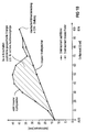
- the course of the torque is illustrated in the diagram according to FIG. 10.
- degrees of angle of the handle of the manual control element are plotted from the switch-off position in the origin to the switch-on position.
- the torque is plotted on the ordinate.
- the lower straight line, which rises to the top right, shows the linear increase in the torque in the energy accumulator 26.
- the non-linear course of the torque is plotted over it. As a result, energy is available for safe tripping operations before the latch is in the on position.
- the angles on the abscissa of the diagram according to FIG. 10 correspond to the deflection of the spring of the energy accumulator 26 of the pawl.
- FIG. 11 The electrical wiring of an undervoltage release 41 together with low-voltage circuit breakers 40, for example line circuit breakers, is shown in FIG. 11 for an application.
- Two switching paths 42 and 43 of the auxiliary switch 6 are shown.
- a converter 44 ensures that the triggering device 1 receives a lower voltage than the mains voltage.
- the implementation of an emergency stop circuit is shown in the exemplary embodiment according to FIG. When the emergency stop switch is open, the undervoltage release drops out, as a result of which coupled low-voltage protection switches 40 are released and switched off, so that the line is interrupted.
- the emergency stop switch is labeled 45.
Abstract
Description
Die Erfindung bezieht sich auf einen Unterspannungsauslöser, insbesondere koppelbar mit Niederspannungsschutzschaltern, dessen elektromagnetische Auslöseeinrichtung mit einem Anker unter Abfallen bei Unterspannung auf eine Entklinkungseinrichtung einwirkt, wobei dessen Anker mittels eines Handbedienungsgliedes und eines Haltehebels beim Einschalten am Magnetsystem der Auslöseeinrichtung angelegt wird, im einzelnen nach Gattungsbegriff von Patentanspruch 1.The invention relates to an undervoltage release, in particular can be coupled to low-voltage circuit breakers, the electromagnetic release device of which acts on an unlatching device with an armature falling under undervoltage, the armature of which is applied to the magnet system of the release device by means of a manual control element and a holding lever when switched on, specifically according to the generic term of
Der Haltehebel hält den Anker zumindest nahe an den Polen des Magnetsystems, bis durch Einschalten mittels eines Hilfsschalters am Anker Spannung angelegt wird, die diesen bei regulären Bedingungen am Magnetsystem halten kann. Diese Einschaltung erfolgt voreilend bezüglich einer gedachten Systemeinschaltstellung, die beispielsweise durch zu koppelnde Leitungsschutzschalter vorgegeben ist.The holding lever holds the armature at least close to the poles of the magnet system until voltage is applied to the armature by switching on by means of an auxiliary switch, which voltage can hold the armature under normal conditions. This switch-on takes place prematurely with respect to an imaginary system switch-on position, which is predetermined, for example, by circuit breakers to be coupled.
Ein bekannter derartiger Unterspannungsauslöser (DE-C-33 08 437) arbeitet mit einem gesonderten Kraftspeicher für das Magnetsystem.A known undervoltage release of this type (DE-C-33 08 437) works with a separate energy store for the magnet system.
Bei einem anderen bekannten Unterspannungsauslöser (DE-C-31 14 717) soll der Aufbau vereinfacht werden; er arbeitet mit einem Andrückhebel und einem Klinkenhebel mit einer gemeinsamen Achse. Um die Auslösezeit eines Systems zu verringern, wird bei einem anderen Unterspannungsauslöser (EP-A-0 331 586) bei einer im wesentlichen dreiteiligen Kinematik aus Klinkenhebel, Auslösehebel und Zwischenhebel eine dritte Achse im Vergleich zum zuvor genannten Auslöser eingeführt.In another known undervoltage release (DE-C-31 14 717) the structure is to be simplified; he works with a pressure lever and a ratchet lever with a common axis. In order to reduce the tripping time of a system, a third axis is introduced in another undervoltage release (EP-A-0 331 586) with an essentially three-part kinematics of ratchet lever, release lever and intermediate lever compared to the aforementioned release.
Der Erfindung liegt die Aufgabe zugrunde, mit einfachen und übersichtlichen Bauteilen einen Unterspannungsauslöser zu entwickeln, der an die verschiedenartigsten Anforderungen in einfacher Weise angepaßt werden kann.The object of the invention is to create an undervoltage release with simple and clear components develop that can be easily adapted to the most diverse requirements.
Die Lösung der geschilderten Aufgabe erfolgt durch einen Unterspannungsauslöser nach Anspruch 1. Der Haltehebel ist danach von einer mit dem Handbedienungsglied gekoppelten Kulisse bis zur Anlage des Ankers am Magnetsystem geführt, wobei die Kulisse kinematisch anschließend einen Freigabebereich aufweist. Die Klinke der Entklinkungseinrichtung ist dabei hinsichtlich des Hilfsschalter und seines Aufbaus so geformt und bzw. oder so positioniert, daß eine Einwirkungsstelle zum Betätigen des Hilfsschalters gebildet ist, wobei in der Einschaltstellung des Unterspannungsauslösers zumindest eine Kontaktstrecke des Hilfsschalters geschlossen ist, um die Wicklung des Magnetsystems an Spannung zu legen. Durch den Freigabebereich der Klinke entfällt, beispielsweise im Vergleich zu einem Unterspannungsauslöser nach DE-C-33 08 437, beim Magnetsystem ein zusätzlicher Kraftspeicher, der durch Niederdrücken gespannt werden muß, um den Anker des Magnetsystems für eine Auslösung freizugeben. Durch die Formgebung der Klinke, die eine Einwirkungsstelle zum Betätigen des Hilfsschalters bildet, können marktgängige Hilfsschalter in geeigneter Weise als Bauteile eingesetzt und angeordnet werden. Durch die Entkopplung von Klinke und Haltehebel läßt sich das beim Einschalten auf die Klinke ausgeübte Drehmoment gemäß Anspruch 2 so steuern, daß bei ausreichend großen Schaltkräften, auch zum Betätigen des Hilfsschalters, dennoch vergleichsweise schwache Verklinkungskräfte anstehen.The above-described object is achieved by an undervoltage release according to
Wenn der Hilfsschalter mit zwei elektrisch parallel liegenden Schaltstrecken auf einem Träger nach Anspruch 3 versehen ist, erzielt man eine vom übrigen System unabhängige und einfache Justiermöglichkeit.If the auxiliary switch is provided with two electrically parallel switching paths on a carrier according to claim 3, one achieves a simple and independent adjustment option from the rest of the system.
Wenn der Unterspannungsauslöser nach Anspruch 4 mit sechs Anschlüssen versehen ist, zwei für das Magnetsystem der Auslöseeinrichtung und vier für den Hilfsschalter, kann man dem Hilfsschalter eingangsseitig eine hohe Betriebsspannung zuführen, die ausgangsseitig durch einen Steuertrafo für die Spule des Magnetsystems herabgesetzt wird, wie es in FIG 11 veranschaulicht ist.If the undervoltage release according to
Da der Haltehebel den Anker nahe an den Polschuhen des Magnetsystems hält, kommt man mit einfachen Magnetsystemen und ungeschliffenen Polflächen aus. Durch einen Unterspannungsauslöser nach Anspruch 5, bei dem das Magnetsystem über eine Schaltung gespeist ist, die die Spannung gleichrichtet und ggf. aufbereitet oder auf andere Werte umsetzt, kann man mit vergleichsweise einfachen und preisgünstigen Magnetsystemen brummfrei arbeiten. Der sonst ohne aufwendige besondere Vorkehrungen übliche Brumm eines mit Wechselspannung betriebenen Magnetsystems kann dadurch auf wirtschaftliche Weise vermieden werden.Since the holding lever holds the armature close to the pole pieces of the magnet system, simple magnet systems and unpolished pole faces are sufficient. An undervoltage release according to
Der erfindungsgemäße Aufbau eines Unterspannungsauslösers ermöglicht es, nach Anspruch 6 einen Arbeitsstromauslöser mit weniger, im übrigen mit gleichen Bauteilen, abzuleiten.The structure of an undervoltage release according to the invention makes it possible to derive a shunt release with fewer, and otherwise with the same components.
Die Anlage für den Justierarm des Hilfsschalters kann durch einen Aufbau nach Anspruch 7 fertigungsgünstig verstellt werden und dadurch justiert werden.The system for the adjustment arm of the auxiliary switch can be adjusted by a structure according to
Der Unterspannungsauslöser kann nach Anspruch 8 mit einem Hilfsschalter arbeiten, dessen Schaltstrecken nach dem Prinzip eines Schnappschalters ausgeführt sind. Hierbei ist die Einwirkungsstelle von der Klinke her beim Hilfsschalter als Stößel ausgeführt, dessen Eindringtiefe die Stellung der Schnappschalter steuert.The undervoltage release can work according to
Die Kulisse für den Haltehebel kann nach Anspruch 9 im Handbedienungsglied in einem Walzenkörper mit der Lagerstelle des Handbedienungsgliedes ausgeführt sein, in dem ein Bogensteg längs eines Sektors am Walzenkörper ausgebildet ist.The backdrop for the holding lever can be designed according to claim 9 in the manual control element in a roller body with the bearing point of the manual control element, in which an arch web is formed along a sector on the roller body.
Die Erfindung soll nun anhand von in der Zeichnung grob schematisch wiedergegebenen Ausführungsbeispielen näher erläutert werden:
- In FIG 1 ist ein Unterspannungsauslöser bei abgenommenem Gehäusedeckel in seiner Ausschaltstellung in Seitenansicht wiedergegeben.
- In FIG 2 ist der Unterspannungsauslöser nach FIG 1 in Einschaltstellung und bei ausreichender Betriebsspannung dargestellt.
- In FIG 3 ist der Unterspannungsauslöser bei einer Zwischenstellung des Handbedienungsgliedes, bei etwa 60°, veranschaulicht, bei der der Haltehebel von der mit dem Handbedienungsglied gekoppelten Kulisse freigegeben ist, so daß Auslösung erfolgen kann.
- In FIG 4 ist dargestellt, daß in einer Stellung nach FIG 3 eine Auslösung durch Abfallen des Ankers des Magnetsystems erfolgt, wobei der Haltehebel mittels eines Koppelgliedes auf die Verklinkungsstelle entklinkend einwirkt.
- In FIG 5 ist zeitlich nach dem Schaltzustand nach FIG 4 wiedergegeben, daß der Haltehebel durch einen Mitnehmer der Klinke wieder in die Einschaltstellung des Magnetsystems überführt wird und daß der Mitnehmer für seitlich anzubauende Geräte, wie Leitungsschutzschalter, sich in der Stellung nach Auslösung befindet.
- In FIG 6 ist veranschaulicht, wie aus einem Unterspannungsauslöser durch Entfernen des Haltehebels und durch Umdrehen des Magnetsystems in eine um 180° in der Zeichenebene gedrehte Position bei im übrigen gleichen Bauteilen ein Arbeitsstromauslöser abgeleitet werden kann. Ein derartiger Arbeitsstromauslöser kann beispielsweise als Fernschalter für seitlich anzubauende Geräte eingesetzt werden.
- In den FIG 7 bis 9 ist veranschaulicht, wie sich beim Einschalten des Unterspannungsauslösers durch das Handbetätigungsorgan die Hebelverhältnisse zum Erzeugen gesteuerter Drehmomente verändern.
- In FIG 10 ist das durch den Kraftspeicher auf die Klinke ausgeübte Drehmoment infolge einer erfindungsgemäßen Steuerung des Drehmoments beispielhaft veranschaulicht.
- In FIG 11 ist ein Beispiel für die Beschaltung der Anschlüsse des Unterspannungsauslösers in Verbindung mit seitlich angebauten Leitungsschutzschaltern wiedergegeben.
- 1 shows an undervoltage release with the housing cover removed in its switched-off position in a side view.
- 2 shows the undervoltage release according to FIG. 1 in the switched-on position and with sufficient operating voltage.
- 3 shows the undervoltage release in an intermediate position of the manual control element, at approximately 60 °, in which the holding lever is released from the link coupled to the manual control element, so that triggering can take place.
- FIG. 4 shows that, in a position according to FIG. 3, the armature of the magnet system triggers, the holding lever having a decoupling effect on the latching point by means of a coupling member.
- FIG. 5 shows in time after the switching state according to FIG. 4 that the holding lever is transferred back into the switch-on position of the magnet system by a catch of the pawl and that the catch for devices to be attached laterally, such as circuit breakers, is in the position after tripping.
- FIG. 6 illustrates how a shunt release can be derived from an undervoltage release by removing the holding lever and by turning the magnet system into a position rotated by 180 ° in the plane of the drawing for the same components. Such a shunt release can be used, for example, as a remote switch for devices to be mounted on the side.
- FIGS. 7 to 9 illustrate how the lever ratios for generating controlled torques change when the undervoltage release is switched on by the manual actuating element.
- In FIG 10, the torque exerted on the pawl by the energy accumulator as a result of a control of the torque according to the invention is exemplified.
- FIG. 11 shows an example of the wiring of the connections of the undervoltage release in connection with side-mounted circuit breakers.
Der Unterspannungsauslöser nach FIG 1 weist eine elektromagnetische Auslöseeinrichtung 1 mit einem Anker 2 auf, der bei Unterspannung vom Magnetsystem abfällt und auf eine Entklinkungseinrichtung 3 einwirkt. Der Anker 2 wird mittels eines Handbedienungsgliedes 4 und eines Haltehebels 5 beim Einschalten am Magnetsystem der Auslöseeinrichtung 1 angelegt, bis durch Einschalten mittels eines Hilfsschalters 6 am Magnetsystem den Anker 2 haltende Spannung angelegt wird. Die Spannung eilt bezüglich einer gedachten Systemeinschaltstellung, wie sie durch zu überwachende Einrichtungen oder seitlich angebaute Leitungsschutzschalter gegeben ist, vor. Unter Anlegen des Ankers 2 ist hierbei zu verstehen, daß er bis auf erlaubte Toleranzen nahe an das Magnetsystem herangeführt wird.The undervoltage release according to FIG. 1 has an
Der Haltehebel 5 ist mit dem Handbedienungsglied 4 durch eine Kulisse 7 bis zur Anlage des Ankers am Magnetsystem geführt, wobei die Kulisse kinematisch anschließend einen Freigabebereich 8 aufweist. Die Klinke 9 ist derart hinsichtlich des Hilfsschalters 6 und seines Aufbaus geformt und bzw. oder positioniert, daß eine Einwirkungsstelle 10 zum Betätigen des Hilfsschalters 6 gebildet ist. In der Einschaltstellung des Unterspannungsauslösers wird hierdurch zumindest eine Kontaktstrecke des Hilfsschalters 6 geschlossen.The
Die Kulisse 7 für den Haltehebel 5 ist im Ausführungsbeispiel im Handbedienungsglied 4 in einem Walzenkörper mit der Lagerstelle 11 des Handbedienungsgliedes als Bogensteg längs eines Sektors des Walzenkörpers ausgeführt. Der Haltehebel 5 wird hierbei durch einen den Bogensteg hintergreifenden Arm als Eingriffskörper 12 der Kulissenführung in seiner Anlagestellung zum Anlegen des Ankers 2 gehalten bis der Freigabebereich 8 beim Weiterdrehen des Handbedienungsgliedes 4 erreicht ist. Die Klinke 9 findet eine Verklinkungsstelle am Koppelglied 15, auf das der Haltehebel 5 das Koppelglied 15 verdrehend und damit entklinkend einwirken kann, wenn der Anker 2 in die Schaltstellung nach FIG 4 abfällt. Die Klinke 9 ist in einem geführten, ortsbeweglichen Lager 16 drehbeweglich und mit dem Handbedienungsglied 4 durch den Bügel 17 verbunden. Die Klinke 9 kann mit einem angeformten Eingriffskörper 18 auf einen Arm 19 des Mitnehmers 14 einwirken und diesen verdrehen, wodurch seitlich angereihte Geräte, beispielsweise Leitungsschutzschalter, ausgelöst werden können.In the exemplary embodiment, the
Der Hilfsschalter 9 mit beispielsweise zwei elektrisch parallelen Schaltstrecken ist auf einem Träger 13 angeordnet, der zumindest zum Justieren unter der Einwirkung der Klinke um eine Lagerstelle 20 des Trägers verschwenkt werden kann, bis der Träger 13 mit seinem Justierarm 21 an einer verstellbaren Justieranlage 22 anliegt. Diese Justieranlage kann durch eine Schraube gebildet werden, insbesondere eine Madenschraube. Diese kann in einem Gehäusespalt selbstschneidend eingebracht werden. Der Hilfsschalter 6 kann mit Schaltstrecken nach dem Prinzip eines Schnappschalters ausgeführt sein, deren Einwirkungsstelle von der Klinke her als Stößel 23 ausgeführt ist, dessen Eindringtiefe die Stellung des Schnappschalters steuert.The
Der Haltehebel 5 weist ein ortsfestes Drehlager 24 auf. Auf den Haltehebel 5 kann ein Arm 25 der Klinke 9 einwirken. Die Klinke 9 ist von einem Kraftspeicher 26 beaufschlagt, der im wesentlichen den Kraftspeicher des Unterspannungsauslösers bildet.The
Der Unterspannungsauslöser weist elektrische Anschlüsse 27 bis 32 in und hinter der Zeichenebene auf, also insgesamt sechs Anschlüsse. Im Ausführungsbeispiel sind zwei Anschlüsse, 27, hinter der Zeichenebene, und 28, hinter der Zeichenebene, für das Magnetsystem der Auslöseeinrichtung 1 vorgesehen. Die Anschlüsse 29 und 30 sind mit einer Schaltstrecke des Hilfsschalters 6 elektrisch verbunden und die Anschlüsse 31 und 32 mit einer zweiten Schaltstrecke des Hilfsschalters 6. Zumindest zwischen die Anschlüsse 27 und 28 für die Spule des Magnetsystems der Auslöseeinrichtung 1 ist eine elektrische Schaltung 33 eingeschaltet, die die Spannung gleichrichtet und ggf. aufbereitet oder auf andere Werte umsetzt. Diese Schaltung 33 ist beispielhaft als Flachbaugruppe ausgeführt. Die Schaltstrecken des Hilfsschalters 6 sind geschlossen, solange der Stößel 23 des Hilfsschalters 6 durch die Einwirkungsstelle 10 der Klinke 9 eingedrückt ist.The undervoltage release has
In der Einschaltstellung nach FIG 2 drückt die Klinke 9 den Stössel 23 ein, so daß die Schaltstrecken im Hilfsschalter 6 geschlossen werden. Der Haltehebel 5 ist vom Handbedienungsglied 4 freigegeben und liegt unter der Kraft einer schwachen Feder 34 am Magnetsystem der Auslöseeinrichtung 1 an, wobei der Anker 2 durch elektromagnetische Kräfte gegen die Kraft einer Auslösefeder 35 gehalten wird. Der Haltehebel 5 wird bereits bei einer Griffstellung von etwa 60° des Handbedienungsgliedes 4, zur Einschaltstellung gesehen, von der Kulisse 7 freigegeben und liegt bei geschlossenen Schaltstrecken im Hilfsschalter 6 am Anker 2 an. Der Anker wird bereits durch elektromagnetische Kräfte gehalten. Diese Schaltstellung ist in FIG 3 dargestellt. Wenn bereits beim Einschalten nach FIG 3 eine Unterspannung auftritt, fällt der Anker 2 ab, wie es in FIG 4 wiedergegeben ist. Das Koppelglied 15 wird hierbei im Uhrzeigersinn verdreht, so daß in der Entklinkungseinrichtung 3 die Verklinkungsstelle freigegeben wird und die Klinke 9 mit ihrem Eingriffskörper 18 auf den Mitnehmer 14 einwirkt und ihn unter der Kraft der Klinkenfeder 26 gegen den Uhrzeigersinn verdreht, wobei entsprechend FIG 5 bereits das Magnetsystem der Auslöseeinrichtung 1 wieder in die Einschaltstellung durch Anlegen des Ankers 2 überführt wird. Die Klinke 9 hebt hierbei den Haltehebel 5 durch den Klinkenarm 25 in diese Position.In the switched-on position according to FIG. 2, the
Der Unterspannungsauslöser nach FIG 1 ermöglicht die Ableitung eines Arbeitsstromauslösers nach FIG 6, bei dem der Haltehebel entfernt ist und das Magnetsystem der Auslöseeinrichtung 1 umgedreht montiert ist. Magnetsystem und Entklinkungseinrichtung 3 sind darauf abgestimmt, daß sie ohne Haltehebel im Einwirkungsbereich eines Stössels 36 des Magnetauslösers der Auslöseeinrichtung 1 bei angezogenem Anker 2 infolge eines Arbeitsstromes liegt. Bei einem derartigen Arbeitsstromauslöser kommt man mit den weiteren Bauteilen des Unterspannungsauslösers aus. Er kann als Fernschalter zur Fernauslösung mit dem Mitnehmer 14 gekoppelter seitlich angebauter Leitungsschutzschalter dienen.The undervoltage release according to FIG. 1 enables the derivation of a shunt release according to FIG. 6, in which the holding lever is removed and the magnet system of the
Aus den FIG 7 bis 9, in denen jeweils ein Ausschnitt mit Handbedienungsglied 4, Klinke 9 und Mitnehmer 14 wiedergegeben ist, wird eine Steuerung des vom Kraftspeicher 26 der Klinke ausgeübten Drehmoments bei verschiedenen Griffstellungen des Handbedienungsgliedes 4 veranschaulicht. Die Klinke arbeitet mit dem Kraftspeicher 26 zusammen, der bezüglich seines Angriffpunktes 39 an der Klinke und bezüglich deren Lagerstelle 16 zum Handbedienungsglied 4 sowie bezüglich eines Hebelarmes 37 des Kraftspeichers, gebildet bis zum Angriffspunkt 39 des Kraftspeichers 26 an der Klinke, durch Abstimmen der Hebelarme 37 und 38 das Drehmoment in gewollter Weise von der Stellung des Handbedienungsgliedes 4 abhängig macht. Der Kraftspeicher 26 entfaltet beim Überführen der Klinke 9 in die Einschaltstellung zunächst einen überproportionalen nicht linearen Anstieg des Drehmomentes auf die Klinke. Wesentlich ist weiter, daß der Kraftspeicher 26 infolge der Bemessung des Abstandes der Lagerstelle 16 der Klinke von ihrer Verklinkungsstelle am Mitnehmer 14 in der Einschaltstellung verhältnismäßig geringe Kräfte auf die Verklinkungsstelle zur Wirkung bringt. Die Klinke 9 ist weiter darauf durch geeignete Formgebung und Anordnung abgestimmt, daß die Einwirkungsstelle 10 auf den Hilfsschalter beim Einschalten verhältnismäßig hohe Kräfte ausübt.A control of the torque exerted by the
Der Verlauf des Drehmomentes ist im Diagramm nach FIG 10 veranschaulicht. Auf der Abszisse sind von der Ausschaltstellung im Ursprung bis zur Einschaltstellung Winkelgrade des Griffs des Handbedienungsgliedes aufgetragen. Auf der Ordinate ist das Drehmoment aufgetragen. Die untere, nach rechts oben ansteigende Gerade zeigt den linearen Anstieg des Drehmomentes im Kraftspeicher 26. Darüber ist der nichtlineare Verlauf des Drehmomentes aufgetragen. Dadurch steht Energie für sichere Auslösevorgänge vor der Position der Verklinkung in der Einschaltstellung zur Verfügung. Die Winkel auf der Abszisse des Diagramms nach FIG 10 entsprechen der Auslenkung der Feder des Kraftspeichers 26 der Klinke.The course of the torque is illustrated in the diagram according to FIG. 10. On the abscissa, degrees of angle of the handle of the manual control element are plotted from the switch-off position in the origin to the switch-on position. The torque is plotted on the ordinate. The lower straight line, which rises to the top right, shows the linear increase in the torque in the
Die elektrische Beschaltung eines Unterspannungsauslösers 41 zusammen mit angereihten Niederspannungsschutzschaltern 40, beispielsweise Leitungsschutzschaltern, ist in FIG 11 für einen Anwendungsfall dargestellt. Zwei Schaltstrecken 42 und 43 des Hilfsschalters 6 sind wiedergegeben. Ein Wandler 44 sorgt im Ausführungsbeispiel dafür, daß die Auslöseeinrichtung 1 niedrigere Spannung als die Netzspannung erhält. Im Ausführungsbeispiel nach FIG 11 ist die Realisierung einer Not-Aus-Schaltung dargestellt. Bei geöffnetem Not-Aus-Schalter fällt der Unterspannungsauslöser ab, wodurch gekoppelte Niederspannungsschutzschalter 40 entklinkt werden und abschalten, so daß die Leitung unterbrochen wird. Der Not-Aus-Schalter ist mit 45 bezeichnet.The electrical wiring of an
Claims (9)
dadurch gekennzeichnet,
daß der Haltehebel (5) von einer mit dem Handbedienungsglied (4) gekoppelten Kulisse (7) bis zur Anlage des Ankers (2) am Magnetsystem geführt ist, wobei sich an die Kulisse (7) kinematisch ein Freigabebereich (8) anschließt, wobei die Klinke (9) der Entklinkungseinrichtung derart hinsichtlich des Hilfsschalters (6) und seines Aufbaus geformt und bzw. oder positioniert ist, daß eine Einwirkungsstelle (10) zum Betätigen des Hilfsschalters (6) gebildet ist und daß in der Einschaltstellung der Unterspannungsauslöser zumindest eine Kontaktstrecke (42,43) des Hilfsschalters (6) geschlossen ist.Undervoltage release, in particular can be coupled to low-voltage circuit breakers, the electromagnetic release device (1) of which acts on an unlatching device (3) with an armature (2) while dropping in the event of undervoltage, the armature (2) of which by means of a manual control element (4) and a holding lever (5) Switching on is applied to the magnet system of the triggering device (1) until, by switching on by means of an auxiliary switch (6) on the magnet system, the armature-holding voltage is prematurely applied with respect to an imaginary system switch-on position,
characterized,
that the holding lever (5) is guided from a link (7) coupled to the manual control element (4) until the armature (2) bears against the magnet system, with a release area (8) kinematically connecting to the link (7), the The pawl (9) of the unlatching device is shaped and / or positioned with respect to the auxiliary switch (6) and its structure such that an action point (10) for actuating the auxiliary switch (6) is formed and that in the switched-on position of the undervoltage release at least one contact path ( 42,43) of the auxiliary switch (6) is closed.
dadurch gekennzeichnet,
daß die Klinke (9) mit einem Kraftspeicher (26) zusammenarbeitet, der bezüglich seines Angriffpunktes (39) an der Klinke (9) und bezüglich deren Lagerstelle (16) zum Handbedienungsglied (4) sowie bezüglich eines Hebelarmes (37) des Kraftspeichers, gebildet bis zum Angriffspunkt (39) des Kraftspeichers an der Klinke beim Überführen der Klinke (9) in die Einschaltstellung zunächst einen überproportionalen nichtlinearen Anstieg des Drehmomentes auf die Klinke ergibt und daß der Kraftspeicher (26) infolge der Bemessung des Abstandes der Lagerstelle (16) der Klinke von ihrer Verklinkungsstelle in der Einschaltstellung verhältnismäßig geringe Kräfte auf die Verklinkungsstelle zur Wirkung bringt, wobei die Klinke (9) derart angeordnet ist, daß die Einwirkungsstelle (10) auf den Hilfsschalter (6) beim Einschalten verhältnismäßig hohe Kräfte ausübt.Undervoltage release according to claim 1,
characterized,
that the pawl (9) cooperates with an energy accumulator (26) which, with regard to its point of attack (39) on the pawl (9) and with respect to its bearing point (16) to the manual control element (4) and with respect to a lever arm (37) of the energy accumulator up to the point of application (39) of the energy accumulator on the pawl when the pawl (9) is moved into the switch-on position, a disproportionate one non-linear increase in the torque on the pawl and that the energy accumulator (26), due to the dimensioning of the distance of the bearing point (16) of the pawl from its latching point in the switched-on position, brings about relatively small forces on the latching point, the latch (9) in this way it is arranged that the point of action (10) exerts relatively high forces on the auxiliary switch (6) when switched on.
dadurch gekennzeichnet,
daß der Hilfsschalter (6) mit zwei elektrisch parallelen Schaltstrecken (42,43) versehen ist und auf einem Träger (13) angeordnet ist, der zumindest zum Justieren drehbeweglich unter der Einwirkung der Klinke mit einem Justierarm (21) an einer verstellbaren Justieranlage (22) anliegt.Undervoltage release according to claim 1 or 2,
characterized,
that the auxiliary switch (6) is provided with two electrically parallel switching paths (42, 43) and is arranged on a carrier (13) which, at least for adjustment, can be rotated under the action of the pawl with an adjusting arm (21) on an adjustable adjusting system (22 ) is present.
dadurch gekennzeichnet,
daß sechs Anschlüsse (27,28,29,30,31,32) vorgesehen sind, zwei für das Magnetsystem der Auslöseeinrichtung (1) und vier für den Hilfsschalter (6), wobei zwei Anschlüsse (30,32) am Eingang mit zwei Anschlüssen (29,31) am Ausgang des Hilfsschalters bei zwei Schaltstrecken des Hilfsschalters vorgesehen sind.Undervoltage release according to one of Claims 1 to 3,
characterized,
that six connections (27, 28, 29, 30, 31, 32) are provided, two for the magnet system of the tripping device (1) and four for the auxiliary switch (6), two connections (30, 32) at the input with two connections (29,31) are provided at the output of the auxiliary switch for two switching distances of the auxiliary switch.
dadurch gekennzeichnet,
daß das Magnetsystem über eine Schaltung (33) gespeist ist, die die Spannungs gleichrichtet und ggf. aufbereitet oder auf andere Werte umsetzt.Undervoltage release according to one of claims 1 to 4,
characterized,
that the magnet system is fed via a circuit (33) which rectifies the voltage and, if necessary, prepares it or converts it to other values.
dadurch gekennzeichnet,
daß die Entklinkungseinrichtung darauf abgestimmt ist, daß sie ohne Haltehebel (5) bei umgedreht angeordnetem Magnetsystem im Einwirkungsbereich seines Stößels bleibt.Undervoltage release according to one of claims 1 to 5,
characterized,
that the unlatching device is matched to the fact that it remains in the area of action of its plunger without the holding lever (5) when the magnet system is turned upside down.
dadurch gekennzeichnet,
daß die Anlage (22) für den Justierarm (21) von einer Madenschraube gebildet ist, die in einen Gehäusespalt selbstschneidend eingebracht ist.Undervoltage release according to claim 3,
characterized,
that the system (22) for the adjusting arm (21) is formed by a grub screw which is introduced self-tapping into a housing gap.
dadurch gekennzeichnet,
daß der Hilfsschalter (6) mit Schaltstrecken nach dem Prinzip eines Schnappschalters ausgeführt ist, dessen Einwirkungsstelle von der Klinke her als Stößel (23) ausgeführt ist, dessen Eindringtiefe die Stellung des Schnappschalters steuert.Undervoltage release according to one of claims 1 to 5,
characterized,
that the auxiliary switch (6) is designed with switching paths on the principle of a snap switch, the point of action from the pawl is designed as a plunger (23), the depth of penetration of which controls the position of the snap switch.
dadurch gekennzeichnet,
daß die Kulisse (7) für den Haltehebel (5) im Handbedienungsglied 4 in einem Walzenkörper mit der Lagerstelle (11) des Handbedienungsgliedes als Bogensteg längs eines Sektors ausgebildet ist.Undervoltage release according to one of claims 1 to 5,
characterized,
that the backdrop (7) for the holding lever (5) in the manual control element 4 is formed in a roller body with the bearing (11) of the manual control element as an arch web along a sector.
Priority Applications (4)
| Application Number | Priority Date | Filing Date | Title |
|---|---|---|---|
| EP96109274A EP0813219B1 (en) | 1996-06-10 | 1996-06-10 | Undervoltage release device |
| AT96109274T ATE209828T1 (en) | 1996-06-10 | 1996-06-10 | UNDERVOLTAGE RELEASE |
| DE59608320T DE59608320D1 (en) | 1996-06-10 | 1996-06-10 | Undervoltage release |
| TR97/00468A TR199700468A1 (en) | 1996-06-10 | 1997-06-05 | Low voltage release mode. |
Applications Claiming Priority (1)
| Application Number | Priority Date | Filing Date | Title |
|---|---|---|---|
| EP96109274A EP0813219B1 (en) | 1996-06-10 | 1996-06-10 | Undervoltage release device |
Publications (2)
| Publication Number | Publication Date |
|---|---|
| EP0813219A1 true EP0813219A1 (en) | 1997-12-17 |
| EP0813219B1 EP0813219B1 (en) | 2001-11-28 |
Family
ID=8222879
Family Applications (1)
| Application Number | Title | Priority Date | Filing Date |
|---|---|---|---|
| EP96109274A Expired - Lifetime EP0813219B1 (en) | 1996-06-10 | 1996-06-10 | Undervoltage release device |
Country Status (4)
| Country | Link |
|---|---|
| EP (1) | EP0813219B1 (en) |
| AT (1) | ATE209828T1 (en) |
| DE (1) | DE59608320D1 (en) |
| TR (1) | TR199700468A1 (en) |
Cited By (10)
| Publication number | Priority date | Publication date | Assignee | Title |
|---|---|---|---|---|
| FR2824183A1 (en) * | 2001-04-27 | 2002-10-31 | Fuji Electric Co Ltd | UNDERVOLTAGE TRIGGERING DEVICE INCLUDING AN EARLY AUXILIARY SWITCH FOR A CIRCUIT BREAKER |
| FR2828330A1 (en) * | 2001-08-06 | 2003-02-07 | Fuji Electric Co Ltd | PROTECTION SWITCH |
| FR2831321A1 (en) * | 2001-10-19 | 2003-04-25 | Fuji Electric Co Ltd | Under voltage switching mechanism having rapid acting auxiliary switch having under voltage activated lever switching contact closing and end shaft laterally rotating engagement lever/switching auxiliary switch. |
| DE10238533B4 (en) * | 2001-08-27 | 2006-12-07 | Mitsubishi Denki K.K. | Circuit breaker |
| EP1981054A3 (en) * | 2007-04-09 | 2009-11-25 | EATON Corporation | Electrical switching apparatus accessory sub-assembly employing reversible coil frame, and accessory and electrical switching apparatus employing the same |
| WO2010088875A1 (en) * | 2009-02-05 | 2010-08-12 | Siemens Aktiengesellschaft | Tripping apparatus, particularly for circuit breakers |
| EP2110841A3 (en) * | 2008-04-15 | 2011-01-19 | General Electric Company | Solenoid switch and cover |
| EP0980128B1 (en) * | 1998-08-13 | 2011-06-15 | Siemens Aktiengesellschaft | Undervoltage release device |
| FR2961343A1 (en) * | 2010-06-15 | 2011-12-16 | Schneider Electric Ind Sas | AUXILIARY RELEASE DEVICE FOR ASSOCIATED WITH A CIRCUIT BREAKER. |
| CN102347167A (en) * | 2010-07-21 | 2012-02-08 | 西门子公司 | Electrical switch |
Citations (4)
| Publication number | Priority date | Publication date | Assignee | Title |
|---|---|---|---|---|
| FR2503930A1 (en) * | 1981-04-11 | 1982-10-15 | Licentia Gmbh | MINIMUM VOLTAGE TRIGGER FOR POWER CIRCUIT BREAKERS |
| DE3308437A1 (en) * | 1983-03-10 | 1984-09-13 | Klöckner-Moeller Elektrizitäts GmbH, 5300 Bonn | Under-voltage trip device for electrical low-voltage protection circuit breakers |
| EP0331586A1 (en) * | 1988-03-04 | 1989-09-06 | Merlin Gerin | Actuating mechanism of an auxiliary tripping block for a modular circuit breaker |
| EP0656641A2 (en) * | 1993-12-03 | 1995-06-07 | Moeller GmbH | Trip unit for circuit breaker or protective switches |
-
1996
- 1996-06-10 EP EP96109274A patent/EP0813219B1/en not_active Expired - Lifetime
- 1996-06-10 AT AT96109274T patent/ATE209828T1/en not_active IP Right Cessation
- 1996-06-10 DE DE59608320T patent/DE59608320D1/en not_active Expired - Lifetime
-
1997
- 1997-06-05 TR TR97/00468A patent/TR199700468A1/en unknown
Patent Citations (4)
| Publication number | Priority date | Publication date | Assignee | Title |
|---|---|---|---|---|
| FR2503930A1 (en) * | 1981-04-11 | 1982-10-15 | Licentia Gmbh | MINIMUM VOLTAGE TRIGGER FOR POWER CIRCUIT BREAKERS |
| DE3308437A1 (en) * | 1983-03-10 | 1984-09-13 | Klöckner-Moeller Elektrizitäts GmbH, 5300 Bonn | Under-voltage trip device for electrical low-voltage protection circuit breakers |
| EP0331586A1 (en) * | 1988-03-04 | 1989-09-06 | Merlin Gerin | Actuating mechanism of an auxiliary tripping block for a modular circuit breaker |
| EP0656641A2 (en) * | 1993-12-03 | 1995-06-07 | Moeller GmbH | Trip unit for circuit breaker or protective switches |
Cited By (15)
| Publication number | Priority date | Publication date | Assignee | Title |
|---|---|---|---|---|
| EP0980128B1 (en) * | 1998-08-13 | 2011-06-15 | Siemens Aktiengesellschaft | Undervoltage release device |
| FR2824183A1 (en) * | 2001-04-27 | 2002-10-31 | Fuji Electric Co Ltd | UNDERVOLTAGE TRIGGERING DEVICE INCLUDING AN EARLY AUXILIARY SWITCH FOR A CIRCUIT BREAKER |
| FR2828330A1 (en) * | 2001-08-06 | 2003-02-07 | Fuji Electric Co Ltd | PROTECTION SWITCH |
| DE10238533B4 (en) * | 2001-08-27 | 2006-12-07 | Mitsubishi Denki K.K. | Circuit breaker |
| FR2831321A1 (en) * | 2001-10-19 | 2003-04-25 | Fuji Electric Co Ltd | Under voltage switching mechanism having rapid acting auxiliary switch having under voltage activated lever switching contact closing and end shaft laterally rotating engagement lever/switching auxiliary switch. |
| EP1981054A3 (en) * | 2007-04-09 | 2009-11-25 | EATON Corporation | Electrical switching apparatus accessory sub-assembly employing reversible coil frame, and accessory and electrical switching apparatus employing the same |
| EP2110841A3 (en) * | 2008-04-15 | 2011-01-19 | General Electric Company | Solenoid switch and cover |
| WO2010088875A1 (en) * | 2009-02-05 | 2010-08-12 | Siemens Aktiengesellschaft | Tripping apparatus, particularly for circuit breakers |
| US8547190B2 (en) | 2009-02-05 | 2013-10-01 | Siemens Aktiengesellschaft | Tripping apparatus, particularly for circuit breakers |
| FR2961343A1 (en) * | 2010-06-15 | 2011-12-16 | Schneider Electric Ind Sas | AUXILIARY RELEASE DEVICE FOR ASSOCIATED WITH A CIRCUIT BREAKER. |
| CN102290295A (en) * | 2010-06-15 | 2011-12-21 | 施耐德电器工业公司 | Auxiliary trip device designed to be associated with circuit breaker unit |
| EP2398034A1 (en) * | 2010-06-15 | 2011-12-21 | Schneider Electric Industries SAS | Auxiliary trip device for a breaker block |
| CN102290295B (en) * | 2010-06-15 | 2015-03-25 | 施耐德电器工业公司 | Auxiliary trip device designed to be associated with circuit breaker unit |
| CN102347167A (en) * | 2010-07-21 | 2012-02-08 | 西门子公司 | Electrical switch |
| CN102347167B (en) * | 2010-07-21 | 2015-11-18 | 西门子公司 | Electric switch |
Also Published As
| Publication number | Publication date |
|---|---|
| ATE209828T1 (en) | 2001-12-15 |
| DE59608320D1 (en) | 2002-01-10 |
| TR199700468A1 (en) | 1997-12-21 |
| EP0813219B1 (en) | 2001-11-28 |
Similar Documents
| Publication | Publication Date | Title |
|---|---|---|
| DE3531710C2 (en) | Switching device with variable composition that can be realized by assembling module elements | |
| DE8024641U1 (en) | Circuit breaker | |
| DE102014108090B3 (en) | Adapter system with an adapter for busbars and an adapter connection module | |
| DE102004040288A1 (en) | Circuit breaker with short-circuit and overload trip indication and corresponding procedure | |
| EP0813219B1 (en) | Undervoltage release device | |
| DE3713537A1 (en) | REVERSE SWITCHING DEVICE WITH OVERCURRENT PROTECTION | |
| DE2948959C2 (en) | Electromagnetic switching device | |
| DE19754072C1 (en) | Switchgear unit consisting of a switchgear and a coupled leading auxiliary switch | |
| EP1964139A1 (en) | Command device with switching element monitoring | |
| DE102006037225A1 (en) | Switching unit | |
| DE3214935C2 (en) | Drive device for electric switches | |
| EP0517049A1 (en) | Leakage current release with permanent magnet | |
| DE3824116A1 (en) | CIRCUIT AND DEVICE FOR PROTECTED SUPPLY OF A LOAD WITH THE AID OF ELECTRONIC AND ELECTROMECHANICAL INTERRUPTORS | |
| DE2115034A1 (en) | Electrical circuit breaker for fault current, overcurrent and short circuit protection | |
| DE4208716A1 (en) | Safety switch for coupling to operating or driven module - has trigger mechanism released by pin from either master or slave module to move from locked position to one of two release positions | |
| DE102006036187A1 (en) | Switching device with actuator | |
| DE2343908C2 (en) | Circuit breaker with overcurrent and auxiliary tripping | |
| EP0956578A2 (en) | Fast connection switching device | |
| DE4304772C1 (en) | Switch mechanism for electric motor protection switch - has spring-biased pivoted wiper between knee-lever system and movable contact bridge carrier | |
| AT406531B (en) | Fault current protection switch | |
| EP0592007B1 (en) | Switching device | |
| DE19853901C1 (en) | Undervoltage release | |
| DE4339425B4 (en) | Switch lock for a residual current circuit breaker | |
| EP0389075B1 (en) | Power circuit breaker with an undervoltage tripping device | |
| DE10218525A1 (en) | Undervoltage release device for switching device |
Legal Events
| Date | Code | Title | Description |
|---|---|---|---|
| PUAI | Public reference made under article 153(3) epc to a published international application that has entered the european phase |
Free format text: ORIGINAL CODE: 0009012 |
|
| AK | Designated contracting states |
Kind code of ref document: A1 Designated state(s): AT BE DE FR GB IT |
|
| 17P | Request for examination filed |
Effective date: 19980608 |
|
| GRAG | Despatch of communication of intention to grant |
Free format text: ORIGINAL CODE: EPIDOS AGRA |
|
| 17Q | First examination report despatched |
Effective date: 20010208 |
|
| GRAG | Despatch of communication of intention to grant |
Free format text: ORIGINAL CODE: EPIDOS AGRA |
|
| GRAH | Despatch of communication of intention to grant a patent |
Free format text: ORIGINAL CODE: EPIDOS IGRA |
|
| GRAH | Despatch of communication of intention to grant a patent |
Free format text: ORIGINAL CODE: EPIDOS IGRA |
|
| GRAA | (expected) grant |
Free format text: ORIGINAL CODE: 0009210 |
|
| AK | Designated contracting states |
Kind code of ref document: B1 Designated state(s): AT BE DE FR GB IT |
|
| RBV | Designated contracting states (corrected) |
Designated state(s): AT BE DE FR GB IT |
|
| REF | Corresponds to: |
Ref document number: 209828 Country of ref document: AT Date of ref document: 20011215 Kind code of ref document: T |
|
| GBT | Gb: translation of ep patent filed (gb section 77(6)(a)/1977) |
Effective date: 20011128 |
|
| REG | Reference to a national code |
Ref country code: IE Ref legal event code: FG4D Free format text: GERMAN |
|
| REG | Reference to a national code |
Ref country code: GB Ref legal event code: IF02 |
|
| REF | Corresponds to: |
Ref document number: 59608320 Country of ref document: DE Date of ref document: 20020110 |
|
| ET | Fr: translation filed | ||
| PGFP | Annual fee paid to national office [announced via postgrant information from national office to epo] |
Ref country code: AT Payment date: 20020529 Year of fee payment: 7 |
|
| PGFP | Annual fee paid to national office [announced via postgrant information from national office to epo] |
Ref country code: GB Payment date: 20020610 Year of fee payment: 7 |
|
| PGFP | Annual fee paid to national office [announced via postgrant information from national office to epo] |
Ref country code: BE Payment date: 20020625 Year of fee payment: 7 |
|
| REG | Reference to a national code |
Ref country code: IE Ref legal event code: FD4D |
|
| PLBE | No opposition filed within time limit |
Free format text: ORIGINAL CODE: 0009261 |
|
| STAA | Information on the status of an ep patent application or granted ep patent |
Free format text: STATUS: NO OPPOSITION FILED WITHIN TIME LIMIT |
|
| 26N | No opposition filed | ||
| PG25 | Lapsed in a contracting state [announced via postgrant information from national office to epo] |
Ref country code: GB Free format text: LAPSE BECAUSE OF NON-PAYMENT OF DUE FEES Effective date: 20030610 Ref country code: AT Free format text: LAPSE BECAUSE OF NON-PAYMENT OF DUE FEES Effective date: 20030610 |
|
| PG25 | Lapsed in a contracting state [announced via postgrant information from national office to epo] |
Ref country code: BE Free format text: LAPSE BECAUSE OF NON-PAYMENT OF DUE FEES Effective date: 20030630 |
|
| BERE | Be: lapsed |
Owner name: *SIEMENS A.G. Effective date: 20030630 |
|
| GBPC | Gb: european patent ceased through non-payment of renewal fee |
Effective date: 20030610 |
|
| PGFP | Annual fee paid to national office [announced via postgrant information from national office to epo] |
Ref country code: FR Payment date: 20110630 Year of fee payment: 16 |
|
| PGFP | Annual fee paid to national office [announced via postgrant information from national office to epo] |
Ref country code: IT Payment date: 20120626 Year of fee payment: 17 |
|
| REG | Reference to a national code |
Ref country code: FR Ref legal event code: ST Effective date: 20130228 |
|
| PG25 | Lapsed in a contracting state [announced via postgrant information from national office to epo] |
Ref country code: FR Free format text: LAPSE BECAUSE OF NON-PAYMENT OF DUE FEES Effective date: 20120702 |
|
| PG25 | Lapsed in a contracting state [announced via postgrant information from national office to epo] |
Ref country code: IT Free format text: LAPSE BECAUSE OF NON-PAYMENT OF DUE FEES Effective date: 20130610 |
|
| PGFP | Annual fee paid to national office [announced via postgrant information from national office to epo] |
Ref country code: DE Payment date: 20140819 Year of fee payment: 19 |
|
| REG | Reference to a national code |
Ref country code: DE Ref legal event code: R119 Ref document number: 59608320 Country of ref document: DE |
|
| PG25 | Lapsed in a contracting state [announced via postgrant information from national office to epo] |
Ref country code: DE Free format text: LAPSE BECAUSE OF NON-PAYMENT OF DUE FEES Effective date: 20160101 |