EP0813072A2 - Räumlich definiertes Datenübertragungssystem mit hoher Genauigkeit - Google Patents
Räumlich definiertes Datenübertragungssystem mit hoher Genauigkeit Download PDFInfo
- Publication number
- EP0813072A2 EP0813072A2 EP97303943A EP97303943A EP0813072A2 EP 0813072 A2 EP0813072 A2 EP 0813072A2 EP 97303943 A EP97303943 A EP 97303943A EP 97303943 A EP97303943 A EP 97303943A EP 0813072 A2 EP0813072 A2 EP 0813072A2
- Authority
- EP
- European Patent Office
- Prior art keywords
- electronic devices
- infrared
- spatial
- portable electronic
- electronic device
- Prior art date
- Legal status (The legal status is an assumption and is not a legal conclusion. Google has not performed a legal analysis and makes no representation as to the accuracy of the status listed.)
- Granted
Links
Images


Classifications
-
- G—PHYSICS
- G01—MEASURING; TESTING
- G01S—RADIO DIRECTION-FINDING; RADIO NAVIGATION; DETERMINING DISTANCE OR VELOCITY BY USE OF RADIO WAVES; LOCATING OR PRESENCE-DETECTING BY USE OF THE REFLECTION OR RERADIATION OF RADIO WAVES; ANALOGOUS ARRANGEMENTS USING OTHER WAVES
- G01S5/00—Position-fixing by co-ordinating two or more direction or position line determinations; Position-fixing by co-ordinating two or more distance determinations
- G01S5/16—Position-fixing by co-ordinating two or more direction or position line determinations; Position-fixing by co-ordinating two or more distance determinations using electromagnetic waves other than radio waves
-
- G—PHYSICS
- G01—MEASURING; TESTING
- G01C—MEASURING DISTANCES, LEVELS OR BEARINGS; SURVEYING; NAVIGATION; GYROSCOPIC INSTRUMENTS; PHOTOGRAMMETRY OR VIDEOGRAMMETRY
- G01C11/00—Photogrammetry or videogrammetry, e.g. stereogrammetry; Photographic surveying
- G01C11/04—Interpretation of pictures
- G01C11/06—Interpretation of pictures by comparison of two or more pictures of the same area
Definitions
- the present invention relates to a system that enables transfer of electronic data to electronic devices at predetermined spatial locations. More specifically, the present invention relates to a system for determining position of portable electronic devices with submeter scale precision, and allowing data transfers between portable electronic devices according to their known spatial position.
- portable computing devices include laptop, notebook, subnotebook, or handheld computers, personal digital assistants, personal organizers, personal communicators (e.g. two way pagers) or digitally readable smart cards.
- portable devices are rapidly becoming more powerful and sophisticated with inclusion of high speed processors, attached harddrives, PCMCIA modem, cursor controllers, and small format keyboard or graphical input device (e.g., for pen based personal digital assistants).
- a personal digital assistant can be linked through a wireless connection (radio or infrared) to a desktop computer to transfer contents of an electronic address book.
- a smartcard can be used to enable financial transactions through debit transfers, while a two way pager can be used to receive and send a limited range of preprogrammed responses.
- a PDA can be configured to be location sensitive, with a user being able to send data to other spatially specified devices. This function would be particularly advantageous for exchange of information such as "business card" data in a crowded room having many operating PDA's.
- a user of a first PDA would merely have to depress a button to initiate transfer of information to an adjacent second PDA, without specifically knowing himself the network address, e-mail address, logical address, or other identifying address information of the second PDA.
- a computer network capable of interacting with both PDA's through wireless links and storing spatial information concerning PDA location receives the information from the first PDA, determines which PDA is adjacent to the first user, and retransmits that information to the second PDA.
- This spatial functionality is extendible, with users of PDA's being able to direct transmission of business card data to all PDA's in a specified spatial location, in a specified radius or area, or even to specified rooms in a building.
- the present invention provides a system for transferring digital information to spatially localizable portable electronic devices, comprising a plurality of portable electronic devices, each portable electronic device including means providing wireless communication, a spatial localizing module for determining spatial location with submeter precision of each of the plurality of electronic devices, and a communication module connected to the spatial localizing module for mediating wireless communication between a first portable electronic device and those members of the plurality of portable electronic devices in a user defined spatial location.
- the invention further provides a method for transferring digital information to spatially localizable electronic devices, the method comprising the steps of (a) determining spatial location of each of a plurality of electronic devices with submeter precision, (b) selecting a user defined spatial region for communicating with the plurality of electronic devices, and (c) facilitating wireless communication between a first portable electronic device and those members of the plurality of portable electronic devices in the user defined spatial region.
- the invention further provides a system for precisely locating one or more electronic devices, according to claim 5 of the appended claims.
- a range of spatial locations and orientations can be specified, with transmission to adjacent electronic devices, to all electronic devices in a room, to all electronic devices in a particular orientation or direction, or even to all electronic devices at spatial locations within a specified range (e.g. within two meters).
- the present invention advantageously allows a user of a portable electronic device to interact more intuitively with other portable devices based on their perceived physical, spatial location, rather than on a logical location defined by their network address or name.
- a computer network having wireless transmission and reception capability is used to maintain information concerning location of all portable electronic devices. Identifying spatial location of multiple electronic devices with a spatial resolution on the order of centimeters or millimeters is enabled by use of a low cost spatial localizing system that employs infrared signaling devices (infrared identification tags) attached or integrated into the electronic devices.
- the spatial localizing system includes at least two conventional and widely commercially available CCD video cameras having overlapping field of views. The video cameras are capable of detecting both visible light and infrared, and are further configured to provide a sequence of images at predefined frame rates.
- One or more infrared identification tags for providing modulated infrared signals are positioned in a room or area within the overlapping field of view of the video cameras, and an image processing system is used to extract the modulated infrared signals from the sequence of images and identify the spatial location of the infrared tag using information obtained from both visible light images and infrared images.
- infrared identification tags intermittently emit infrared detection signals at a rate less than the frame rate of the video cameras to establish spatial location.
- the pattern of infrared blinking seen through comparison of multiple frames of the video cameras can be used to positively identify infrared tags and transfer identification information or other data.
- identification and tracking of multiple tags in parallel can be achieved.
- data acquisition from a room can utilize large numbers of identifying infrared tags attached to objects.
- infrared tags can be deployed to describe particular positions, locations, or areas in a room, providing useful benchmarks for establishing spatial locations.
- multiple tags attached to a movable object can be used to determine and track orientation, as well as location, of the object. This permits data transfer to be defined in relation to the orientation of an electronic device. For example, a command to transfer data to other electronic devices to the left of a particular users electronic device is possible.
- use of two or more attached tags could allow determinatior of the angle of rotation of an object.
- Use of multiple tags also alleviates problems associated with obscuration of an object or electronic device, and increases accuracy of position determination.
- multiple identification tags can be used to increase the rate of data transfer.
- passive infrared reflectors as tags (with a separate, room mounted infrared flasher providing infrared light on demand), or to use infrared identification tags that are activated only in response to an identification request.
- the present invention uses relatively inexpensive and commonly available components such as infrared transmitters and CCD video cameras to provide highly precise spatial localization of tagged electronic devices.
- Suitable high quality CCD video cameras are widely employed for consumer security systems. Because of the economies of scale, such CCD video cameras are quite inexpensive, making them ideal for this application.
- the infrared signaling system is essentially invisible to users, while still being easy for automated systems to locate and interpret without elaborate image processing techniques.
- the present invention can be quickly implemented after computer network connected video cameras are installed, and does not require complex setup or initialization. Using a limited number of inexpensive video cameras, the present invention allows for tracking spatial location of large numbers of tagged electronic devices, enabling data transfer between electronic devices situated at specified spatial locations with sub-meter precision via a suitably configured computer network.
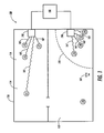
- Figure 1 illustrates a system 100 for enabling transfer of electronic data to electronic devices at predetermined spatial locations.
- the system 100 includes a plurality of spatial localizing modules 190 and 192 that function to detect absolute spatial location of particular electronic devices.
- the spatial localizing modules 190 and 192 track spatial positions of electronic devices and additionally provide a mechanism for electronic data transfer in conjunction with computer network 180.
- the position and size, and number of spatial localizing modules 190 and 192 is only representative, and not intended to limit the present invention.
- the computer network 180 may include multiple computers, workstations, specialized image processing hardware, servers, or other information processing and connectivity hardware. Multiple spatial localizing modules connected to network 180 can be used, and a wide variety of mechanisms for determining spatial location can be employed, including image based techniques, ultrasound or other acoustic techniques, or even radio based techniques such as differential GPS.
- the spatial localizing modules 190 and 192 track a plurality of electronic devices, indicated as circles 170-178.
- the electronic devices are distributed throughout two rooms 152 and 154 of a building 150, with a spatial localizing module respectively located in each room.
- a scale marker 101 representing a distance of one meter is shown for scale.
- the electronic devices 170-178 in the building 150 may be, for example, personal digital assistants, two-way pagers, laptop or notebook computers, computer tablets, or any other electronic device capable of wireless communication through radio, infrared, acoustic or other transmission links.
- communication links for data transmission are generically illustrated by wavy lines 161, 163, 165, 167, and 181, 183, 185, and 185.
- the system 100 is capable of determining both relative and absolute spatial location of other electronic devices with submeter precision, and mediate transmission or reception of data only to specified electronic devices 170-178 based on the relative or absolute spatial location of those electronic devices.
- centimeter or even millimeter scale spatial localization is possible, however, for many applications submeter precision is adequate.
- Data transmission to or between electronic devices based on spatial location criteria can take many forms.
- a user with electronic device 170 may desire to transmit data only to an adjacently located electronic device 172.
- the user can merely depress an appropriate button, use a mouse to click a menu command such as "transfer adjacent", or other suitable initiating action, to initiate a data transfer to device 172.
- the system 100 operating with submeter precision, is able to determine that the spatial location of other nearby electronic devices 174 and 176 are not as close to device 170 as adjacent electronic device 172, and accordingly not direct data to those other nearby electronic devices.
- Another possible mode of spatially limited data transfer uses transfer to electronic devices within a certain radius.
- a user of electronic device 170 could transmit data to all devices within about 5 meters. All electronic devices 172, 174, and 176 within that radius (indicated generally by dotted line 195) would be able receive a data transmission, while an electronic device 178 outside dotted line 195 would not receive a data transmission.
- This mode of data transfer is particularly useful in larger rooms with groups of people independently interacting.
- Inter-room transfers are yet another mode of data transfer enabled in a building 150 equipped with a system 100. For example, a user could send electronic data to all electronic devices 171, 173, 175, and 177 in room 154, without sending that data to any electronic devices in room 152.
- Still another mode of directed data transmission based on spatial location can be enabled with electronic devices having a graphical user interface capable of displaying a schematic such as illustrated by Figure 1.
- a user could inspect the absolute or relative spatial locations of electronic devices and graphically select those electronic devices that are to receive (or not receive) a data transmission.
- the present invention allows a user of a portable electronic device to interact more intuitively with other portable devices based on their perceived physical and spatial location, with selective data transfer possible using essentially any spatial description typically employed by a user.
- the user of an electronic device does not need to know a logical location defined by the network address or other obscure specification to interact with other electronic devices, only the perceived spatial location on whatever spatial scale is needed, from submeter to building wide.
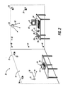
- FIG. 2 is an example of a system 10 for precisely locating infrared signal sources 45 (infrared tags) with centimeter or less scale precision.
- the system 10 includes multiple CCD video cameras 25 positioned in room 12. These video cameras 25 may have a fixed view, such as CCD video cameras 20, 21, 22, and 62, or they may have a movable view such as provided by movable CCD video camera 24.
- Infrared signal sources 45 suitable for spatial localization can be positioned on static or essentially immovable objects such as walls (tags 51, 40, 41, and 42), or desks (tag 44) to help define spatial boundaries and regions. Infrared signal sources 45 can also be positioned on readily movable objects such as a portable electronic device 70 (tag 72) or device 74 (tag 76).
- Image processing for spatial localization and data utilizes a computer system, in this example illustrated by a computer system 60.
- the computer system 60 can of course be located outside room 12, and there is no special requirement for any local computer process control.
- the computer system is connected by wireless or wired links to video cameras 25, and may be stand-alone or connected to a computer network for distributing image processing duties and allowing for high speed data transfer.
- the present system 10 advantageously utilizes emitted infrared signals that are invisible to the human eye yet easily visible to CCD cameras 25.
- the emitted infrared signals from multiple infrared tags provide three dimensional spatial localization for each of those multiple infrared tags.
- the emitted infrared signals are typically intermittent point source flashes of infrared light (infrared blinks) that appear, along with the visual light image, on frames of CCD video cameras. Since the cameras 25 typically provide between about 10 to 30 frames per second of image data, the blink rate is selected to be less than about 5 to 15 blinks per second to ensure capture of infrared images without aliasing problems.
- Subtractive image processing between adjacent image frames or other suitable image processing technique is used to enhance and separate the infrared signal from the visual background, allowing the two dimensional spatial pattern of infrared blinks in each image processed frame to be determined.
- the image processing techniques required to enhance and differentiate infrared point sources in a predominantly visible light image for operation of the present system can be relatively unsophisticated, and do not require elaborate image understanding algorithms.
- the frames from multiple cameras 25 can be spatially multiplexed using conventional image processing techniques to derive a three dimensional spatial localization of each infrared signal source in room 12.
- cameras 25 are arranged so that some combination of at least two cameras have an overlapping field of view on every part of room 12.
- Each camera 25 can be calibrated to allow for spatial localization through the use of reference objects or camera platform control.
- a fixed camera 20 having a fixed focal length is calibrated to allow for computation of the angle of two rays entering its lens based on location of two spots in its image. As will be appreciated by those skilled in the art, this angle can be computed from a published focal length of the lens.
- infrared signal sources at a known distance from a positioned camera that are used as permanent or semi-permanent reference sources for allowing computation of ray angles.
- these reference sources are located at junctions of a room (for example, tags 40 and 42 can be used).
- a new object (such as, for example, infrared tag 41) can be located provided that at least one camera can provide an image of the new object and two reference sources, while a second camera can image the new object and at least one reference source.
- additional infrared reference sources detectable by multiple cameras, it is even possible to extend the method so that camera location with respect to the reference sources need not initially be known.
- infrared signal sources 45 can be used for camera calibration, spatial localization, identification, and data transfer.
- the infrared signal sources 45 can be conceptually divided into active infrared tags 50 that internally generate infrared light 52 (e.g. tag 72 on portable electronic device 70), or passive infrared tags 51 that controllably reflect incident infrared light 54 in response to incident infrared light 32 provided by an infrared light source 30.
- Active infrared tags are generally larger and more expensive than passive infrared tags, requiring a battery or other power source, an infrared emitter such as an infrared LED, and a suitable digital controller.
- an active infrared tag 110 can be built by interconnecting four conventional and widely available modules, including a buffer 112 with IR transmitter LED 122; an amplifier 114 with IR detector 124; a microcontroller 116; and a trigger circuit 118.
- a lithium battery, photoelectric cell, or other long life power source 120 supplies a low voltage power source for driving the modules.
- modules 112, 114, and 116 are held in a power-down mode.
- the fourth module, the trigger circuit 118 is always active but is designed to operate with a very small power-consumption. When the trigger circuit 118 is activated by an external signal 130 such an infrared or optical pulse, the modules 112, 114, and 116 are powered.
- Addressing signals 131 may be received at module 114, decoded by module 116 and then a response signal 132 sent back using transmitter LED 122 from module 112.
- the microcontroller module 116 keeps track of time and after some number of milliseconds or the lack of receiver activity, will return itself (module 116), along with modules 112 and 114, to the power-down state.
- the response signal 132 (infrared pulses) incorporates the identity of the active infrared tag, along with any desired data.
- trigger circuit many differing types can be employed.
- a simple implementation of a trigger circuit includes a low-power astable-oscillator with a long and slightly random period (to avoid repeated tag-signal collisions).
- the trigger circuit could also be designed to be activated by a particularly intense IR flash or it might use another medium such as the reception of a particular radio frequency.
- the trigger circuit can be designed to render the IR detection/amplification module 114 unnecessary.
- Passive infrared tags 51 are an inexpensive altemative to active infrared tags 50. Passive infrared tags 51 controllably reflect infrared light 32 provided by an infrared light source 30.
- the infrared light source 30 can be continuously, intermittently, or periodically operated as required.
- the passive infrared tags 51 each include an infrared reflecting material covered by an alternately light transmissive or light absorptive shutter.
- the shutter is an electrically controlled liquid crystal display (LCD) that normally does not transmit substantial amounts of infrared light.
- a low power electrical signal is applied to convert the shutter from this infrared non-transmissive state to a substantially transmissive state.
- the passive infrared tags 51 can be activated to transmit identification codes and other data in response to an infrared trigger signal. This avoids the need for continuous activation of the LCD shutter mechanism and greatly reduces long term power requirements.
- multiple passive tags can be simultaneously operated, since the spatial localizing camera system of the present invention can unambiguously distinguish between multiple passive tags 51 transmitting information in response to the same activation signal.
- Figure 3 is a graph illustrating IR pulse detection versus time, with three distinct modes of pulsed operation shown. Operation of a tag 50 or 51 in locating or initialization mode is represented by a series of detected periodic infrared pulses 104 identified by bracket 106. To conserve power, these pulses 104 may actually consist of multiple brief infrared spikes or pulses, at a rate high enough to ensure apparently continuous detection of an infrared signal by the cameras throughout each pulse 104. Of course, IR intensity can be continuously maintained, rather than pulsed, for the duration of each pulse 104 if power is not limited.
- the periodic detected infrared pulses 104 allow for detection of the three dimensional location of a tagged object (e.g. electronic device 70 or 74) by cameras 25 and determination of pulse separation 103 between sequential pulses 104.
- a tagged object e.g. electronic device 70 or 74
- cameras 25 are operated at a frame rate 102 substantially faster than pulse separation 103, with a frame rate two to three times as fast as pulse separation being suggested.
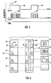
- Detection by cameras 25 of infrared pulses to allow for spatial localization and information transfer is schematically indicated in Figure 4.
- Two sequences of processed image frames 122 (camera 1) and 124 (camera 2) are illustrated.
- the cameras have a partially overlapping field of view with three potential infrared pulse sources.
- Each frame in the sequences 122 and 124 are composite images of several frames, with noninfrared background visual information subtracted to isolate the infrared pulses.
- infrared pulses In frame 130 of camera 1, potential positions 150, 151, and 152 of infrared pulses (represented by an asterisk) are indicated by dotted outline. These positions correspond to potential positions 160, 161, and 162 in frame 170 of a differently positioned camera 2.
- the infrared pulses are isolated in frames 122 and 124 of camera 1 and camera 2 and used as reference points. Two dimensional information from each camera is acquired, and merged with calibration information to derive the three dimensional position of the infrared pulse.
- the three distinct modes of pulsed operation are shown in the frames 122 and 124.
- Operation of an infrared tag 50 or 51 in locating or initialization mode is represented by periodic infrared pulses at position 150.
- an infrared pulse is seen at position 150 in each frame 130-138 of frame sequence 122.
- a corresponding infrared pulse is of course also seen at position 160 in frame sequence 124 for camera 2. This is equivalent to the series of periodic infrared pulses 104 identified by bracket 106 in Figure 3.
- Information transfer from another infrared tag is shown through aperiodic blinking of infrared pulses at position 151 in frames 130-138 of frame sequence 122 (and the corresponding position 161 in frame sequence 124). Absence of an infrared pulse in a frame is interpreted as a binary "0" (e.g. frames 131, 132, and 137), while presence of an infrared pulse is interpreted as a binary "1" (e.g. frames 130, 133, 135, 136, 138). Accordingly, as illustrated in Figure 4, the binary sequence "1001 ... 1101" can be determined. This binary sequence can be header information, data, identification, packet control information, error correction information, or any other necessary information that might be transmitted from tags 50 or 51.
- the infrared pulses can be stopped to conserve power.
- the tags can of course be reactivated to again identify location of tags and transfer identification information and other data. In Figure 4, this is illustrated by the pattern of infrared pulses at position 152 in frame sequence 122 (and the corresponding position 162 in frame sequence 124). To conserve power, no infrared pulses are emitted during a time period covering frames 130-136. In response to an activation signal, a periodic series of infrared pulses is emitted for localization and initialization purposes, as seen in frames 137 and 138.
- the present system allows for tracking of multiple portable objects (e.g. an electronic device 70 or 74 with respectively attached tag 72 and 76).
- portable objects e.g. an electronic device 70 or 74 with respectively attached tag 72 and 76.
- large numbers of portable objects can be tracked in parallel with high spatial precision, without requiring use of sophisticated tracking techniques to determine tag identification.
- bit transfer is closely associated with the frame rate of the cameras, the relatively low frame rate of widely available low cost cameras limits the theoretical data transfer rate to 10 or 20 bits per second. In practice, because of the necessary overhead associated with error control, bit transfer rates will be even lower.
- One possible way of overcoming this problem is the use of secondary high speed data communication channels for data transfer, while low data transfer rate infrared pulse/camera detection systems are used for spatial localization.
- One example of a dual communication channel system is illustrated in Figures 5 and 6.
- Figure 5 is a graph illustrating IR detection versus time for two separate infrared communication channels.
- Infrared pulses 204 of communication channel 1 are detected by cameras operating at a frame rate 202, using processes described in connection with Figures 3 and 4.
- a separate, higher speed infrared communication channel 2 with much shorter infrared pulses is detectable by a separate (non-camera based) infrared communication system.
- infrared pulses in accordance with applicable IRDA (Infrared Data Association) standards can be used for data transfer on channel 2, although any high speed communication channel, including radio or optical messaging, can be used.
- IRDA Infrared Data Association
- the infrared pulses of channel 1 are used for spatial localization of an infrared tag, while a time coincident communication on channel 2 provides high speed data transfer.
- a high speed infrared communication system operating at about 19.2 kilobits per second includes an infrared tag 57 and a high speed infrared detector 64 attached to computer 60.
- Spatial localization is provided by cameras 25 detecting low speed infrared pulses, while any time coincident data received on the high speed channel is associated with a tag at the identified spatial location.
- use of time coincident communication results in a somewhat reduced data throughput due to statistically determinable data collisions (when two or more tags simultaneously transmit data, resulting in destructive data overlap), but is adequate for most situations.
- Time coincident data transfer methods in accordance with the present invention can be better understood with reference to Figure 6.
- Two image processed frame sequences 222 and 224 taken from different cameras are illustrated, along with an example of high speed data (boxes 270, 272, 274, and 276) time coincidently received with the indicated frames.
- Data can be received from three separate tags located at three different spatial positions (positions 250, 251, and 252 frame sequence 222, positions 260, 261, and 262 in frame sequence 224).
- an infrared pulse (denoted by an asterisk) can be positively located in three dimensions given the two dimensional frame sequences 222 and 224.
- the spatial location data is correlated with the high speed data to provide spatial localization of a specifically identified tag attached a portable electronic device or other object.
- Figure 6 illustrates several possible outcomes for time coincident spatial localization methods in accordance with the present invention.
- Frame 230 shows a spatially localizable infrared pulse at position 250.
- Time coincident data 270 is attributed to a tag emitting the infrared pulse position at position 250, assuming there is no data collision.
- Data collision can occur when two or more data packets are simultaneously received, or when the spatially localizable infrared pulses overlap.
- Frame 231 illustrates one situation without data collision, with an infrared pulse at position 252 being correlated with identification data 272. However, if two or more tags are active during the same time period, as seen in frame 232, the received signal 274 is the garbled result of a data packet collision, and the signal is ignored.
- tags After preprogrammed random delays (seen in frame 233) or active requests to retransmit, the tags are again activated, with hopefully non-overlapping data transfer to allow for unique identification. Note that in certain cases of infrared pulse overlap, a data collision does not necessarily occur, and it may be possible to link spatial location and data through consideration of previously received infrared spatial locations.
- infrared tags and CCD cameras are a preferred low cost system for spatial localization of portable electronic devices
- alternative techniques for spatially localizing electronic devices with centimeter scale precision can also be used.
- systems based on differential GPS, ultrasound ranging, inertial tracking, or multiple station, low power radio reception can be used.
- these alternative systems are generally more difficult to calibrate, control, and maintain at centimeter scale precision than the foregoing infrared tag tracking system using CCD video cameras.
Applications Claiming Priority (2)
| Application Number | Priority Date | Filing Date | Title |
|---|---|---|---|
| US665161 | 1996-06-14 | ||
| US08/665,161 US5793630A (en) | 1996-06-14 | 1996-06-14 | High precision spatially defined data transfer system |
Publications (3)
| Publication Number | Publication Date |
|---|---|
| EP0813072A2 true EP0813072A2 (de) | 1997-12-17 |
| EP0813072A3 EP0813072A3 (de) | 1999-05-26 |
| EP0813072B1 EP0813072B1 (de) | 2004-09-15 |
Family
ID=24668982
Family Applications (1)
| Application Number | Title | Priority Date | Filing Date |
|---|---|---|---|
| EP97303943A Expired - Lifetime EP0813072B1 (de) | 1996-06-14 | 1997-06-06 | Räumlich definiertes Datenübertragungssystem mit hoher Genauigkeit |
Country Status (4)
| Country | Link |
|---|---|
| US (1) | US5793630A (de) |
| EP (1) | EP0813072B1 (de) |
| JP (1) | JP4021970B2 (de) |
| DE (1) | DE69730651T2 (de) |
Cited By (11)
| Publication number | Priority date | Publication date | Assignee | Title |
|---|---|---|---|---|
| EP1068607A1 (de) | 1998-04-03 | 2001-01-17 | Image Guided Technologies, Inc. | Drahtloses optisches instrument zur positionsmessung und verfahren hierfür |
| DE19959387A1 (de) * | 1999-12-09 | 2001-06-13 | Philipp Paul Spangenberg | Verfahren zur Kommunikation zwischen einer elektronischen Recheneinheit mit ausreichend hoher Speicherkapazität zur globalen Datenverwaltung im System und beliebig vielen Personal Digital Assistants über Infrarotsignal |
| EP2006002A1 (de) * | 2006-04-11 | 2008-12-24 | Sony Computer Entertainment Inc. | Unterhaltungssystem und prozessor |
| WO2013059160A1 (en) * | 2011-10-17 | 2013-04-25 | Kla-Tencor Corporation | Acquisition of information for a construction site |
| US9702709B2 (en) | 2007-06-28 | 2017-07-11 | Apple Inc. | Disfavored route progressions or locations |
| US9702721B2 (en) | 2008-05-12 | 2017-07-11 | Apple Inc. | Map service with network-based query for search |
| US9891055B2 (en) | 2007-06-28 | 2018-02-13 | Apple Inc. | Location based tracking |
| US9979776B2 (en) | 2009-05-01 | 2018-05-22 | Apple Inc. | Remotely locating and commanding a mobile device |
| US10064158B2 (en) | 2007-06-28 | 2018-08-28 | Apple Inc. | Location aware mobile device |
| US10299071B2 (en) | 2005-04-04 | 2019-05-21 | X One, Inc. | Server-implemented methods and systems for sharing location amongst web-enabled cell phones |
| US10368199B2 (en) | 2008-06-30 | 2019-07-30 | Apple Inc. | Location sharing |
Families Citing this family (110)
| Publication number | Priority date | Publication date | Assignee | Title |
|---|---|---|---|---|
| US6137476A (en) * | 1994-08-25 | 2000-10-24 | International Business Machines Corp. | Data mouse |
| JPH1056609A (ja) * | 1996-04-15 | 1998-02-24 | Canon Inc | 画像記録方法、通信方法、画像記録装置、通信装置及び媒体 |
| JPH1096605A (ja) * | 1996-09-24 | 1998-04-14 | Komatsu Ltd | 画像処理による位置計測方法および装置 |
| US6885846B1 (en) * | 1997-03-31 | 2005-04-26 | Texas Instruments Incorporated | Low power wireless network |
| US6560461B1 (en) | 1997-08-04 | 2003-05-06 | Mundi Fomukong | Authorized location reporting paging system |
| US6677987B1 (en) * | 1997-12-03 | 2004-01-13 | 8×8, Inc. | Wireless user-interface arrangement and method |
| US6324296B1 (en) * | 1997-12-04 | 2001-11-27 | Phasespace, Inc. | Distributed-processing motion tracking system for tracking individually modulated light points |
| US6122520A (en) | 1998-02-13 | 2000-09-19 | Xerox Corporation | System and method for obtaining and using location specific information |
| FI112897B (fi) * | 1998-03-03 | 2004-01-30 | Nokia Corp | Menetelmä tiedonsiirtoverkossa ja tiedonsiirtolaite |
| JP3841132B2 (ja) * | 1998-06-01 | 2006-11-01 | 株式会社ソニー・コンピュータエンタテインメント | 入力位置検出装置及びエンタテインメントシステム |
| US6795215B1 (en) * | 2000-05-23 | 2004-09-21 | Silverbrook Research Pty Ltd | Print engine/controller and printhead interface chip incorporating the engine/controller |
| US8161129B2 (en) * | 1999-06-24 | 2012-04-17 | Sony Corporation | Communication system, network system, information controller and terminal equipment |
| WO2001017298A1 (en) | 1999-09-02 | 2001-03-08 | Automated Business Companies | Communication and proximity authorization systems |
| US6798349B1 (en) * | 1999-10-04 | 2004-09-28 | Xerox Corporation | Passive microwave tag identification system |
| US7229017B2 (en) * | 1999-11-23 | 2007-06-12 | Xerox Corporation | Laser locating and tracking system for externally activated tags |
| US6542083B1 (en) * | 1999-11-23 | 2003-04-01 | Xerox Corporation | Electronic tag position detection using radio broadcast |
| FR2807901B1 (fr) * | 2000-04-14 | 2002-11-15 | Thomson Broadcast Systems | Dispositif de transmission video entre une camera et une regie |
| JP3678404B2 (ja) * | 2000-05-12 | 2005-08-03 | 株式会社東芝 | 映像情報処理装置 |
| US8060389B2 (en) | 2000-06-07 | 2011-11-15 | Apple Inc. | System and method for anonymous location based services |
| US6456234B1 (en) | 2000-06-07 | 2002-09-24 | William J. Johnson | System and method for proactive content delivery by situation location |
| US8073565B2 (en) | 2000-06-07 | 2011-12-06 | Apple Inc. | System and method for alerting a first mobile data processing system nearby a second mobile data processing system |
| US6880048B1 (en) * | 2000-06-08 | 2005-04-12 | Palm, Source, Inc. | Method and apparatus for fault-tolerant update of flash ROM contents |
| US7630721B2 (en) | 2000-06-27 | 2009-12-08 | Ortiz & Associates Consulting, Llc | Systems, methods and apparatuses for brokering data between wireless devices and data rendering devices |
| US9380414B2 (en) | 2000-06-27 | 2016-06-28 | Ortiz & Associates Consulting, Llc | Systems, methods and apparatuses for brokering data between wireless devices, servers and data rendering devices |
| US7071814B1 (en) * | 2000-07-31 | 2006-07-04 | Motorola, Inc. | Contextually aware network announcements of people |
| US7203518B2 (en) * | 2001-02-20 | 2007-04-10 | International Business Machines Corporation | Method and apparatus for simplified data dispensation to and from digital systems |
| CA2439002C (en) | 2001-03-09 | 2009-11-24 | Radianse, Inc. | A system and method for performing object association using a location tracking system |
| US20030060158A1 (en) * | 2001-09-24 | 2003-03-27 | Sarnoff Corporation | Infrastructure-based communications network |
| US7653655B2 (en) * | 2001-12-17 | 2010-01-26 | Sony Corporation | Data communication system, data communication apparatus, and data communication method for generating or detecting an event |
| USRE45705E1 (en) * | 2001-12-17 | 2015-09-29 | Sony Corporation | Data communication system, data communication apparatus, and data communication method for generating or detecting an event |
| US6972682B2 (en) | 2002-01-18 | 2005-12-06 | Georgia Tech Research Corporation | Monitoring and tracking of assets by utilizing wireless communications |
| US7969472B2 (en) * | 2002-03-27 | 2011-06-28 | Xerox Corporation | Automatic camera steering control and video conferencing |
| US7256709B2 (en) * | 2002-04-01 | 2007-08-14 | Electro Industries/Gauge Tech | Meter with IrDA port |
| US20040204831A1 (en) * | 2002-10-30 | 2004-10-14 | Denis Pochuev | System and method of locating a resource device from a wireless device |
| DE10318156B4 (de) * | 2003-04-17 | 2005-09-01 | Diehl Ako Stiftung & Co. Kg | Verfahren zur Bekanntgabe eines Gerätes in einem System |
| US20050146507A1 (en) * | 2004-01-06 | 2005-07-07 | Viredaz Marc A. | Method and apparatus for interfacing with a graphical user interface using a control interface |
| US8521185B2 (en) * | 2004-02-28 | 2013-08-27 | Charles Martin Hymes | Wireless communications with visually-identified targets |
| US7911446B2 (en) * | 2004-07-13 | 2011-03-22 | Hewlett-Packard Development Company, L.P. | Networked keyboard and mouse drivers |
| US7505607B2 (en) * | 2004-12-17 | 2009-03-17 | Xerox Corporation | Identifying objects tracked in images using active device |
| US9489717B2 (en) | 2005-01-31 | 2016-11-08 | Invention Science Fund I, Llc | Shared image device |
| US20060170956A1 (en) | 2005-01-31 | 2006-08-03 | Jung Edward K | Shared image devices |
| US9124729B2 (en) * | 2005-01-31 | 2015-09-01 | The Invention Science Fund I, Llc | Shared image device synchronization or designation |
| US9082456B2 (en) | 2005-01-31 | 2015-07-14 | The Invention Science Fund I Llc | Shared image device designation |
| US20060221197A1 (en) * | 2005-03-30 | 2006-10-05 | Jung Edward K | Image transformation estimator of an imaging device |
| US8902320B2 (en) | 2005-01-31 | 2014-12-02 | The Invention Science Fund I, Llc | Shared image device synchronization or designation |
| US9910341B2 (en) | 2005-01-31 | 2018-03-06 | The Invention Science Fund I, Llc | Shared image device designation |
| US8606383B2 (en) * | 2005-01-31 | 2013-12-10 | The Invention Science Fund I, Llc | Audio sharing |
| US9191611B2 (en) | 2005-06-02 | 2015-11-17 | Invention Science Fund I, Llc | Conditional alteration of a saved image |
| US10003762B2 (en) | 2005-04-26 | 2018-06-19 | Invention Science Fund I, Llc | Shared image devices |
| US9451200B2 (en) | 2005-06-02 | 2016-09-20 | Invention Science Fund I, Llc | Storage access technique for captured data |
| US9819490B2 (en) | 2005-05-04 | 2017-11-14 | Invention Science Fund I, Llc | Regional proximity for shared image device(s) |
| US9001215B2 (en) | 2005-06-02 | 2015-04-07 | The Invention Science Fund I, Llc | Estimating shared image device operational capabilities or resources |
| US9621749B2 (en) | 2005-06-02 | 2017-04-11 | Invention Science Fund I, Llc | Capturing selected image objects |
| US8681225B2 (en) | 2005-06-02 | 2014-03-25 | Royce A. Levien | Storage access technique for captured data |
| US9942511B2 (en) | 2005-10-31 | 2018-04-10 | Invention Science Fund I, Llc | Preservation/degradation of video/audio aspects of a data stream |
| US9967424B2 (en) | 2005-06-02 | 2018-05-08 | Invention Science Fund I, Llc | Data storage usage protocol |
| US8964054B2 (en) | 2006-08-18 | 2015-02-24 | The Invention Science Fund I, Llc | Capturing selected image objects |
| US20070222865A1 (en) | 2006-03-15 | 2007-09-27 | Searete Llc, A Limited Liability Corporation Of The State Of Delaware | Enhanced video/still image correlation |
| US20070109411A1 (en) * | 2005-06-02 | 2007-05-17 | Searete Llc, A Limited Liability Corporation Of The State Of Delaware | Composite image selectivity |
| US9076208B2 (en) | 2006-02-28 | 2015-07-07 | The Invention Science Fund I, Llc | Imagery processing |
| JP2006323525A (ja) * | 2005-05-17 | 2006-11-30 | Nec Corp | 光タグ、読み取り装置、光タグ管理方法、光タグ管理システム、光タグ管理プログラム、及び記録媒体 |
| US7330122B2 (en) | 2005-08-10 | 2008-02-12 | Remotemdx, Inc. | Remote tracking and communication device |
| US7394366B2 (en) * | 2005-11-15 | 2008-07-01 | Mitel Networks Corporation | Method of detecting audio/video devices within a room |
| JP2008015970A (ja) * | 2006-07-10 | 2008-01-24 | Tokai Rika Co Ltd | 光通信システム |
| US7936262B2 (en) | 2006-07-14 | 2011-05-03 | Securealert, Inc. | Remote tracking system with a dedicated monitoring center |
| US8797210B2 (en) | 2006-07-14 | 2014-08-05 | Securealert, Inc. | Remote tracking device and a system and method for two-way voice communication between the device and a monitoring center |
| US7737841B2 (en) | 2006-07-14 | 2010-06-15 | Remotemdx | Alarm and alarm management system for remote tracking devices |
| US20080051033A1 (en) * | 2006-08-28 | 2008-02-28 | Charles Martin Hymes | Wireless communications with visually- identified targets |
| JP2008070923A (ja) * | 2006-09-12 | 2008-03-27 | Ritsumeikan | 認証システム、認証方法、及び端末 |
| JP4888102B2 (ja) * | 2006-12-18 | 2012-02-29 | 日本電気株式会社 | 光タグ管理方法、光タグ管理システム、光タグ管理プログラム、及び記録媒体 |
| US8098150B2 (en) * | 2007-05-25 | 2012-01-17 | Palo Alto Research Center Incorporated | Method and system for locating devices with embedded location tags |
| US8175802B2 (en) | 2007-06-28 | 2012-05-08 | Apple Inc. | Adaptive route guidance based on preferences |
| US8762056B2 (en) | 2007-06-28 | 2014-06-24 | Apple Inc. | Route reference |
| US8463238B2 (en) | 2007-06-28 | 2013-06-11 | Apple Inc. | Mobile device base station |
| US8204684B2 (en) | 2007-06-28 | 2012-06-19 | Apple Inc. | Adaptive mobile device navigation |
| US8275352B2 (en) | 2007-06-28 | 2012-09-25 | Apple Inc. | Location-based emergency information |
| US8290513B2 (en) | 2007-06-28 | 2012-10-16 | Apple Inc. | Location-based services |
| US9109904B2 (en) | 2007-06-28 | 2015-08-18 | Apple Inc. | Integration of map services and user applications in a mobile device |
| US8311526B2 (en) | 2007-06-28 | 2012-11-13 | Apple Inc. | Location-based categorical information services |
| US8774825B2 (en) | 2007-06-28 | 2014-07-08 | Apple Inc. | Integration of map services with user applications in a mobile device |
| US8180379B2 (en) | 2007-06-28 | 2012-05-15 | Apple Inc. | Synchronizing mobile and vehicle devices |
| US8332402B2 (en) | 2007-06-28 | 2012-12-11 | Apple Inc. | Location based media items |
| US8127246B2 (en) | 2007-10-01 | 2012-02-28 | Apple Inc. | Varying user interface element based on movement |
| US8977294B2 (en) | 2007-10-10 | 2015-03-10 | Apple Inc. | Securely locating a device |
| US8222996B2 (en) | 2007-12-31 | 2012-07-17 | Intel Corporation | Radio frequency identification tags adapted for localization and state indication |
| US8355862B2 (en) | 2008-01-06 | 2013-01-15 | Apple Inc. | Graphical user interface for presenting location information |
| US8452529B2 (en) | 2008-01-10 | 2013-05-28 | Apple Inc. | Adaptive navigation system for estimating travel times |
| WO2009111702A2 (en) | 2008-03-07 | 2009-09-11 | Remotemdx | A system and method for monitoring individuals using a beacon and intelligent remote tracking device |
| US8644843B2 (en) | 2008-05-16 | 2014-02-04 | Apple Inc. | Location determination |
| US8359643B2 (en) | 2008-09-18 | 2013-01-22 | Apple Inc. | Group formation using anonymous broadcast information |
| US8816855B2 (en) | 2008-10-21 | 2014-08-26 | At&T Intellectual Property I, L.P. | Methods, computer program products, and systems for providing automated video tracking via radio frequency identification |
| US8260320B2 (en) | 2008-11-13 | 2012-09-04 | Apple Inc. | Location specific content |
| US8666367B2 (en) | 2009-05-01 | 2014-03-04 | Apple Inc. | Remotely locating and commanding a mobile device |
| US8660530B2 (en) | 2009-05-01 | 2014-02-25 | Apple Inc. | Remotely receiving and communicating commands to a mobile device for execution by the mobile device |
| TW201115451A (en) * | 2009-10-20 | 2011-05-01 | Ind Tech Res Inst | A vectoring data transfer system and method based on sensor assisted positioning method |
| US8514070B2 (en) | 2010-04-07 | 2013-08-20 | Securealert, Inc. | Tracking device incorporating enhanced security mounting strap |
| DE102010046740A1 (de) * | 2010-09-28 | 2012-03-29 | E:Cue Control Gmbh | Verfahren zur Lokalisierung von Lichtquellen, Computerprogramm und Lokalisierungseinheit |
| US9562973B2 (en) * | 2013-02-25 | 2017-02-07 | Honeywell International Inc. | Multimode device for locating and identifying items |
| US11334037B2 (en) * | 2013-03-01 | 2022-05-17 | Comcast Cable Communications, Llc | Systems and methods for controlling devices |
| US11423464B2 (en) | 2013-06-06 | 2022-08-23 | Zebra Technologies Corporation | Method, apparatus, and computer program product for enhancement of fan experience based on location data |
| US9715005B2 (en) | 2013-06-06 | 2017-07-25 | Zih Corp. | Method, apparatus, and computer program product improving real time location systems with multiple location technologies |
| US20140361890A1 (en) | 2013-06-06 | 2014-12-11 | Zih Corp. | Method, apparatus, and computer program product for alert generation using health, fitness, operation, or performance of individuals |
| US20150178817A1 (en) * | 2013-06-06 | 2015-06-25 | Zih Corp. | Method, apparatus, and computer program product for enhancement of fan experience based on location data |
| US9699278B2 (en) | 2013-06-06 | 2017-07-04 | Zih Corp. | Modular location tag for a real time location system network |
| US10437658B2 (en) | 2013-06-06 | 2019-10-08 | Zebra Technologies Corporation | Method, apparatus, and computer program product for collecting and displaying sporting event data based on real time data for proximity and movement of objects |
| US20150149250A1 (en) * | 2013-06-06 | 2015-05-28 | Zih Corp. | Method, apparatus, and computer program product to ascertain supply and demand analytics and outputting events based on real-time data for proximity and movement of individuals and objects |
| CN106461754B (zh) | 2014-06-05 | 2019-10-11 | 斑马技术公司 | 用于自适应开窗和高分辨率toa确定的接收器处理器 |
| WO2015186043A1 (en) | 2014-06-06 | 2015-12-10 | Zih Corp. | Method, apparatus, and computer program product improving real time location systems with multiple location technologies |
| AU2016228847B2 (en) * | 2015-03-10 | 2021-05-13 | Zodiac Pool Systems Llc | Automatic addressing scheme for pool system controllers and compatible remote devices |
| JP2021131234A (ja) * | 2020-02-18 | 2021-09-09 | 富士フイルムビジネスイノベーション株式会社 | 発光装置およびプログラム |
Citations (7)
| Publication number | Priority date | Publication date | Assignee | Title |
|---|---|---|---|---|
| DE4101156A1 (de) * | 1991-01-14 | 1992-07-16 | Audiocinema Electronic Und Med | Verfahren und einrichtung zur ortung und koordinatenbestimmung von objekten |
| US5280287A (en) * | 1992-06-30 | 1994-01-18 | The United States Of America As Represented By The Secretary Of The Navy | Coded identification and positioning system |
| US5363185A (en) * | 1992-12-23 | 1994-11-08 | The United States Of America As Represented By The Secretary Of The Air Force | Method and apparatus for identifying three-dimensional coordinates and orientation to a robot |
| US5365266A (en) * | 1991-12-10 | 1994-11-15 | Carpenter Loren C | Video imaging method and apparatus for audience participation |
| US5479408A (en) * | 1994-02-22 | 1995-12-26 | Will; Craig A. | Wireless personal paging, communications, and locating system |
| US5493692A (en) * | 1993-12-03 | 1996-02-20 | Xerox Corporation | Selective delivery of electronic messages in a multiple computer system based on context and environment of a user |
| WO1996015636A1 (en) * | 1994-11-16 | 1996-05-23 | Highwaymaster Communications, Inc. | Locating system and method using a mobile communications network |
Family Cites Families (24)
| Publication number | Priority date | Publication date | Assignee | Title |
|---|---|---|---|---|
| US3506791A (en) * | 1967-01-16 | 1970-04-14 | Josef Halaby | Telephone system for directing calls to persons instead of stations |
| US3739329A (en) * | 1971-05-24 | 1973-06-12 | Recognition Devices | Electronic system for locating |
| US4217588A (en) * | 1975-04-16 | 1980-08-12 | Information Identification Company, Inc. | Object monitoring method and apparatus |
| US4275385A (en) * | 1979-08-13 | 1981-06-23 | Bell Telephone Laboratories, Incorporated | Infrared personnel locator system |
| US5202929A (en) * | 1979-09-24 | 1993-04-13 | Lemelson Jerome H | Data system and method |
| US4303904A (en) * | 1979-10-12 | 1981-12-01 | Chasek Norman E | Universally applicable, in-motion and automatic toll paying system using microwaves |
| US4912471A (en) * | 1983-11-03 | 1990-03-27 | Mitron Systems Corporation | Interrogator-responder communication system |
| US4688026A (en) * | 1984-05-15 | 1987-08-18 | Scribner James R | Method of collecting and using data associated with tagged objects |
| US5099346A (en) * | 1988-01-27 | 1992-03-24 | Spectrix Corporation | Infrared communications network |
| US5027314A (en) * | 1988-03-17 | 1991-06-25 | United Manufacturing Co., Inc. | Apparatus and method for position reporting |
| US4952928A (en) * | 1988-08-29 | 1990-08-28 | B. I. Incorporated | Adaptable electronic monitoring and identification system |
| US5122959A (en) * | 1988-10-28 | 1992-06-16 | Automated Dispatch Services, Inc. | Transportation dispatch and delivery tracking system |
| US5119104A (en) * | 1990-05-04 | 1992-06-02 | Heller Alan C | Location system adapted for use in multipath environments |
| US5640151A (en) * | 1990-06-15 | 1997-06-17 | Texas Instruments Incorporated | Communication system for communicating with tags |
| US5159592A (en) * | 1990-10-29 | 1992-10-27 | International Business Machines Corporation | Network address management for a wired network supporting wireless communication to a plurality of mobile users |
| US5181200A (en) * | 1990-10-29 | 1993-01-19 | International Business Machines Corporation | Handoff method and apparatus for mobile wireless workstation |
| US5068916A (en) * | 1990-10-29 | 1991-11-26 | International Business Machines Corporation | Coordination of wireless medium among a plurality of base stations |
| US5115224A (en) * | 1991-07-05 | 1992-05-19 | Detection Systems, Inc. | Personal security system network |
| US5218344A (en) * | 1991-07-31 | 1993-06-08 | Ricketts James G | Method and system for monitoring personnel |
| US5515419A (en) * | 1992-06-01 | 1996-05-07 | Trackmobile | Tracking system and method for tracking a movable object carrying a cellular phone unit, and integrated personal protection system incorporating the tracking system |
| US5363425A (en) * | 1992-06-29 | 1994-11-08 | Northern Telecom Limited | Method and apparatus for providing a personal locator, access control and asset tracking service using an in-building telephone network |
| US5396243A (en) * | 1992-12-23 | 1995-03-07 | The United States Of America As Represented By The Secretary Of The Air Force | Infrared laser battlefield identification beacon |
| US5353011A (en) * | 1993-01-04 | 1994-10-04 | Checkpoint Systems, Inc. | Electronic article security system with digital signal processing and increased detection range |
| US5594425A (en) * | 1994-10-31 | 1997-01-14 | Peoplenet, Inc. | Locator device |
-
1996
- 1996-06-14 US US08/665,161 patent/US5793630A/en not_active Expired - Lifetime
-
1997
- 1997-05-23 JP JP13326797A patent/JP4021970B2/ja not_active Expired - Lifetime
- 1997-06-06 DE DE69730651T patent/DE69730651T2/de not_active Expired - Lifetime
- 1997-06-06 EP EP97303943A patent/EP0813072B1/de not_active Expired - Lifetime
Patent Citations (7)
| Publication number | Priority date | Publication date | Assignee | Title |
|---|---|---|---|---|
| DE4101156A1 (de) * | 1991-01-14 | 1992-07-16 | Audiocinema Electronic Und Med | Verfahren und einrichtung zur ortung und koordinatenbestimmung von objekten |
| US5365266A (en) * | 1991-12-10 | 1994-11-15 | Carpenter Loren C | Video imaging method and apparatus for audience participation |
| US5280287A (en) * | 1992-06-30 | 1994-01-18 | The United States Of America As Represented By The Secretary Of The Navy | Coded identification and positioning system |
| US5363185A (en) * | 1992-12-23 | 1994-11-08 | The United States Of America As Represented By The Secretary Of The Air Force | Method and apparatus for identifying three-dimensional coordinates and orientation to a robot |
| US5493692A (en) * | 1993-12-03 | 1996-02-20 | Xerox Corporation | Selective delivery of electronic messages in a multiple computer system based on context and environment of a user |
| US5479408A (en) * | 1994-02-22 | 1995-12-26 | Will; Craig A. | Wireless personal paging, communications, and locating system |
| WO1996015636A1 (en) * | 1994-11-16 | 1996-05-23 | Highwaymaster Communications, Inc. | Locating system and method using a mobile communications network |
Cited By (25)
| Publication number | Priority date | Publication date | Assignee | Title |
|---|---|---|---|---|
| EP1068607A4 (de) * | 1998-04-03 | 2009-07-08 | Image Guided Technologies Inc | Drahtloses optisches instrument zur positionsmessung und verfahren hierfür |
| EP1068607A1 (de) | 1998-04-03 | 2001-01-17 | Image Guided Technologies, Inc. | Drahtloses optisches instrument zur positionsmessung und verfahren hierfür |
| DE19959387A1 (de) * | 1999-12-09 | 2001-06-13 | Philipp Paul Spangenberg | Verfahren zur Kommunikation zwischen einer elektronischen Recheneinheit mit ausreichend hoher Speicherkapazität zur globalen Datenverwaltung im System und beliebig vielen Personal Digital Assistants über Infrarotsignal |
| US10299071B2 (en) | 2005-04-04 | 2019-05-21 | X One, Inc. | Server-implemented methods and systems for sharing location amongst web-enabled cell phones |
| US10341809B2 (en) | 2005-04-04 | 2019-07-02 | X One, Inc. | Location sharing with facilitated meeting point definition |
| US10341808B2 (en) | 2005-04-04 | 2019-07-02 | X One, Inc. | Location sharing for commercial and proprietary content applications |
| US10313826B2 (en) | 2005-04-04 | 2019-06-04 | X One, Inc. | Location sharing and map support in connection with services request |
| EP2006002A1 (de) * | 2006-04-11 | 2008-12-24 | Sony Computer Entertainment Inc. | Unterhaltungssystem und prozessor |
| EP2006002A4 (de) * | 2006-04-11 | 2009-11-18 | Sony Computer Entertainment Inc | Unterhaltungssystem und prozessor |
| US8350805B2 (en) | 2006-04-11 | 2013-01-08 | Sony Computer Entertainment Inc. | Entertainment system and processing apparatus |
| US10458800B2 (en) | 2007-06-28 | 2019-10-29 | Apple Inc. | Disfavored route progressions or locations |
| US10952180B2 (en) | 2007-06-28 | 2021-03-16 | Apple Inc. | Location-aware mobile device |
| US11665665B2 (en) | 2007-06-28 | 2023-05-30 | Apple Inc. | Location-aware mobile device |
| US9891055B2 (en) | 2007-06-28 | 2018-02-13 | Apple Inc. | Location based tracking |
| US10064158B2 (en) | 2007-06-28 | 2018-08-28 | Apple Inc. | Location aware mobile device |
| US9702709B2 (en) | 2007-06-28 | 2017-07-11 | Apple Inc. | Disfavored route progressions or locations |
| US11419092B2 (en) | 2007-06-28 | 2022-08-16 | Apple Inc. | Location-aware mobile device |
| US10412703B2 (en) | 2007-06-28 | 2019-09-10 | Apple Inc. | Location-aware mobile device |
| US11221221B2 (en) | 2007-06-28 | 2022-01-11 | Apple Inc. | Location based tracking |
| US10508921B2 (en) | 2007-06-28 | 2019-12-17 | Apple Inc. | Location based tracking |
| US9702721B2 (en) | 2008-05-12 | 2017-07-11 | Apple Inc. | Map service with network-based query for search |
| US10841739B2 (en) | 2008-06-30 | 2020-11-17 | Apple Inc. | Location sharing |
| US10368199B2 (en) | 2008-06-30 | 2019-07-30 | Apple Inc. | Location sharing |
| US9979776B2 (en) | 2009-05-01 | 2018-05-22 | Apple Inc. | Remotely locating and commanding a mobile device |
| WO2013059160A1 (en) * | 2011-10-17 | 2013-04-25 | Kla-Tencor Corporation | Acquisition of information for a construction site |
Also Published As
| Publication number | Publication date |
|---|---|
| JPH1091890A (ja) | 1998-04-10 |
| DE69730651D1 (de) | 2004-10-21 |
| EP0813072B1 (de) | 2004-09-15 |
| EP0813072A3 (de) | 1999-05-26 |
| US5793630A (en) | 1998-08-11 |
| DE69730651T2 (de) | 2005-02-03 |
| JP4021970B2 (ja) | 2007-12-12 |
Similar Documents
| Publication | Publication Date | Title |
|---|---|---|
| US5793630A (en) | High precision spatially defined data transfer system | |
| EP0813040A2 (de) | Räumliches Präzisionskartieren mit kombinierten Video- und Infrarotsignalen | |
| EP0813073A2 (de) | Identifizierung von Gegenständen und Positionsbestimmung mit hoher Genauigkeit mittels kombinierter Video- und Infrarotsignale | |
| US6396438B1 (en) | System and method for locating radio frequency identification tags using three-phase antenna | |
| US6693511B1 (en) | System and method for communicating with dormant radio frequency identification tags | |
| US7023356B2 (en) | System and method for monitoring individuals and objects associated with wireless identification tags | |
| JP4831554B2 (ja) | 総合的広帯域無線通信ネットワーク | |
| EP0629881B1 (de) | Infrarotsystem zur Richtstrahlsteuerung | |
| EP1877822B1 (de) | Rfid-systeme und verfahren mit infrarot-lokalisierung | |
| US5920287A (en) | Radio location system for precisely tracking objects by RF transceiver tags which randomly and repetitively emit wideband identification signals | |
| Hightower et al. | Location systems for ubiquitous computing | |
| US6493649B1 (en) | Detection system for determining positional and other information about objects | |
| US5119104A (en) | Location system adapted for use in multipath environments | |
| US6859485B2 (en) | Geolocation system with controllable tags enabled by wireless communications to the tags | |
| JP2003124880A (ja) | 光データ通信位置決定装置 | |
| US10944474B2 (en) | Dual-mode optical devices for time-of-flight sensing and information transfer | |
| US7474855B2 (en) | Information support system | |
| WO2001022118A2 (en) | System and method for locating radio frequency identification tags using three-phase antenna | |
| US7483338B2 (en) | Ultrasonic locator system and method | |
| EP3667363A1 (de) | Verfahren und vorrichtungen zur bestimmung von rotationsparametern zur umrechnung zwischen koordinatensystemen | |
| JPH1066136A (ja) | 所在位置検出システム | |
| JP2754235B2 (ja) | 移動体へのポーリングシステム | |
| JP2668005B2 (ja) | Idトランスポンダの保管システム | |
| JPH07154846A (ja) | 移動体位置認識システム | |
| JPH0363584A (ja) | 移動体の位置識別システム |
Legal Events
| Date | Code | Title | Description |
|---|---|---|---|
| PUAI | Public reference made under article 153(3) epc to a published international application that has entered the european phase |
Free format text: ORIGINAL CODE: 0009012 |
|
| AK | Designated contracting states |
Kind code of ref document: A2 Designated state(s): DE FR GB |
|
| PUAL | Search report despatched |
Free format text: ORIGINAL CODE: 0009013 |
|
| AK | Designated contracting states |
Kind code of ref document: A3 Designated state(s): AT BE CH DE DK ES FI FR GB GR IE IT LI LU MC NL PT SE |
|
| 17P | Request for examination filed |
Effective date: 19991126 |
|
| AKX | Designation fees paid |
Free format text: DE FR GB |
|
| 17Q | First examination report despatched |
Effective date: 20030328 |
|
| GRAP | Despatch of communication of intention to grant a patent |
Free format text: ORIGINAL CODE: EPIDOSNIGR1 |
|
| GRAS | Grant fee paid |
Free format text: ORIGINAL CODE: EPIDOSNIGR3 |
|
| GRAA | (expected) grant |
Free format text: ORIGINAL CODE: 0009210 |
|
| AK | Designated contracting states |
Kind code of ref document: B1 Designated state(s): DE FR GB |
|
| REG | Reference to a national code |
Ref country code: GB Ref legal event code: FG4D |
|
| REF | Corresponds to: |
Ref document number: 69730651 Country of ref document: DE Date of ref document: 20041021 Kind code of ref document: P |
|
| ET | Fr: translation filed | ||
| PLBE | No opposition filed within time limit |
Free format text: ORIGINAL CODE: 0009261 |
|
| STAA | Information on the status of an ep patent application or granted ep patent |
Free format text: STATUS: NO OPPOSITION FILED WITHIN TIME LIMIT |
|
| 26N | No opposition filed |
Effective date: 20050616 |
|
| REG | Reference to a national code |
Ref country code: FR Ref legal event code: PLFP Year of fee payment: 20 |
|
| PGFP | Annual fee paid to national office [announced via postgrant information from national office to epo] |
Ref country code: GB Payment date: 20160527 Year of fee payment: 20 Ref country code: DE Payment date: 20160524 Year of fee payment: 20 |
|
| PGFP | Annual fee paid to national office [announced via postgrant information from national office to epo] |
Ref country code: FR Payment date: 20160526 Year of fee payment: 20 |
|
| REG | Reference to a national code |
Ref country code: DE Ref legal event code: R071 Ref document number: 69730651 Country of ref document: DE |
|
| REG | Reference to a national code |
Ref country code: GB Ref legal event code: PE20 Expiry date: 20170605 |
|
| PG25 | Lapsed in a contracting state [announced via postgrant information from national office to epo] |
Ref country code: GB Free format text: LAPSE BECAUSE OF EXPIRATION OF PROTECTION Effective date: 20170605 |