EP0812713A2 - Variable temperature control system for vehicles - Google Patents
Variable temperature control system for vehicles Download PDFInfo
- Publication number
- EP0812713A2 EP0812713A2 EP97109513A EP97109513A EP0812713A2 EP 0812713 A2 EP0812713 A2 EP 0812713A2 EP 97109513 A EP97109513 A EP 97109513A EP 97109513 A EP97109513 A EP 97109513A EP 0812713 A2 EP0812713 A2 EP 0812713A2
- Authority
- EP
- European Patent Office
- Prior art keywords
- rotary
- pulley
- vent
- control system
- output shaft
- Prior art date
- Legal status (The legal status is an assumption and is not a legal conclusion. Google has not performed a legal analysis and makes no representation as to the accuracy of the status listed.)
- Granted
Links
Images


Classifications
-
- G—PHYSICS
- G05—CONTROLLING; REGULATING
- G05G—CONTROL DEVICES OR SYSTEMS INSOFAR AS CHARACTERISED BY MECHANICAL FEATURES ONLY
- G05G7/00—Manually-actuated control mechanisms provided with one single controlling member co-operating with one single controlled member; Details thereof
- G05G7/02—Manually-actuated control mechanisms provided with one single controlling member co-operating with one single controlled member; Details thereof characterised by special provisions for conveying or converting motion, or for acting at a distance
-
- B—PERFORMING OPERATIONS; TRANSPORTING
- B60—VEHICLES IN GENERAL
- B60H—ARRANGEMENTS OF HEATING, COOLING, VENTILATING OR OTHER AIR-TREATING DEVICES SPECIALLY ADAPTED FOR PASSENGER OR GOODS SPACES OF VEHICLES
- B60H1/00—Heating, cooling or ventilating devices
- B60H1/00642—Control systems or circuits; Control members or indication devices for heating, cooling or ventilating devices
- B60H1/00814—Control systems or circuits characterised by their output, for controlling particular components of the heating, cooling or ventilating installation
- B60H1/00821—Control systems or circuits characterised by their output, for controlling particular components of the heating, cooling or ventilating installation the components being ventilating, air admitting or air distributing devices
- B60H1/00835—Damper doors, e.g. position control
- B60H1/00857—Damper doors, e.g. position control characterised by the means connecting the initiating means, e.g. control lever, to the damper door
Definitions
- the subject invention is directed to a temperature control system for vehicles and, more particularly, to a variable temperature control system for controlling the temperature of air supplied to a vehicle's passenger compartment.
- temperature controlling is accomplished by controlling the setting of a vent damper or blend door located in the passenger air supply system duct work. Often a rotary knob located at the control panel is drivingly connected to the blend door through a mechanical cable or linkage arrangement. The loads required to operate the blend door have generally required relatively rigid control cables and linkages.
- the subject invention provides an improvement to a control system of the type described which produces a near linear relationship between control knob rotation and output air temperature.
- the invention results in significant reduction in operating knob force to allow use of thin, light pull-pull operating cables. This allows easy routing of the operating cables.
- the invention allows significant reduction in cost as compared to electrical operating systems.
- a rotary temperature control system that includes a manually operable rotary control knob that is operatively connected with a control pulley for producing selective rotation thereof.
- a flexible cable means extends from the control pulley to a vent pulley for producing rotary movement of the vent pulley in response to rotary movement of the control pulley.
- a rotary output shaft is provided for driving a blend door that controls the temperature of a blended output air stream.
- vent pulley and the rotary output shaft are connected by drive means that include non-circular gears providing a drive connection between the vent pulley and the output shaft for producing a predetermined, generally non-linear relationship between rotary movement of the control pulley and rotary movement of the output shaft to produce a generally linear relationship between the rotary movement of the control pulley and the temperature of the air stream throughout a major portion of the rotary movement of the control pulley.
- the drive means further includes a sector gear rotated by the vent pulley.
- the vent pulley and one of the first and second non-circular gears are mounted for rotation about a common axis.
- the drive means includes a housing assembly which houses the vent pulley and the first and second non-circular gears.
- the output shaft extends into the housing and is rotatable about an axis parallel to the axes of rotation of the non-circular gears.
- the use of the described drive arrangement allows the non-circular gears to be designed so as to provide the necessary non-linear movement of the output shaft in response to linear movement of the manually operable rotary control knob.
- This allows a linear relationship between the rotary movement of the manually operable rotary control knob and/or the control pulley relative to the temperature of the air stream.
- this relationship be substantially linear throughout the major portion of the rotary movement of the control pulley, it is possible to modify it slightly to assure that the forces required for knob movement do not become undesirably high or excessive at any point in the control range.
- the drive means including the housing, as well as the vent pulley and the non-circular gears, are formed of plastic and constitute a relatively small, lightweight assembly that can be directly associated with the blend door mounting or drive shaft.
- a further object of the invention is the provision of a rotary temperature control system of the general type described which is highly compact and relatively inexpensive to construct.
- Yet another object of the invention is the provision of a temperature control system that is simple to install and which allows the drive interconnection between the control knob and the blend door to have substantially any desired routing.
- FIGURE 1 shows the overall arrangement of a temperature control system 10 for controlling the temperature of air supplied to the passenger compartment of a motor vehicle.
- a rotary, manually operable control knob 12 is mechanically, drivingly interconnected with a vent damper or blend door 14 that acts to selectively blend or mix outside air and temperature modified air to produce a desired output stream that is connected to the vehicle passenger compartment.
- the control knob 12 is connected through a worm and spur gear assembly 16 with an input or control pulley 18 of a pull-pull cable drive system 20 .
- the output of the pull-pull cable system comprises and output or vent pulley 22 (see FIGURE 3) that is mounted in a suitable housing 24 that forms part of a drive means and gear system 30 that will subsequently be discussed and described in detail.
- the drive means and gear system 30 which provides the drive connection between the pull-pull cable drive system 20 and the output shaft 14a which operates the blend door 14 is particularly designed to produce a predetermined, generally non-linear movement relationship between the rotary movement of the control pulley 12 and the rotary movement of the output shaft 14a to produce a generally linear relationship between the rotary movement of the control pulley 12 and the temperature of the blended air stream supplied to the passenger compartment throughout a major portion of the rotary movement of the control pulley. As will subsequently be described in some detail, this is accomplished through the use of variable ratio, non-circular gearing to compensate for the non-linear relationship between the blend door movement and the mix ratio produced between the blend air streams.
- assembly 30 includes an outer housing that generally comprises a lower housing component 32 and a cover or upper housing component 34 that is suitably joined thereto in any convenient manner, such as by mechanical fasteners, welding, or the like.
- the lower housing component 32 includes a base or bottom wall 36 and an integral, upwardly extending peripheral wall 38 which defines a gear chamber 40 .
- the bottom wall 36 extends laterally beyond the wall 38 in the portion 42 shown to provide a mounting plate and to underlie the cables of pull-pull system 20 that enter into the gear chamber 40 and connect with the vent pulley 22 .
- the housing components could be formed from a variety of different materials but, in the preferred embodiment, are molded plastic components formed from a relatively high strength plastic such as ABS.
- the first post 44 is arranged to receive the vent pulley 22 and is generally aligned between the pair of openings 50 - 52 that provide receiving elements that are adapted to clamp about the outer sheaths of the pull-pull cables.
- the pull cables are, in turn, received in a suitable guide groove 56 formed in the outer surface of the vent pulley 22 .
- the central hub 22a and through opening 22b of the vent pulley are sized and related to the first post to allow free, but smooth rotary movement therebetween.
- first non-circular gear 60 Driven directly from the vent pulley is a first non-circular gear 60 that is mounted for direct rotation with the vent pulley 22 about the axis defined by post 44 .
- first non-circular gear 60 and the vent pulley 22 are molded as a single, unitary element with the non-circular gear 60 positioned beneath the vent pulley 22 as best seen in FIGURES 3 and 6.
- gears and pulleys could be formed from a variety of different material but, in the subject embodiment, are preferably molded from a plastic or resinous material such as type PA66 nylon.
- a second non-circular gear 66 is arranged to cooperate with the first non-circular gear 60 and is arranged and designed so as to have a central through opening 66b for rotation on the second post 46 .
- the second non-circular gear 66 is designed such that it is mounted in horizontal alignment with the first non-circular gear 60 .
- a circular pinion gear 70 Positioned immediately above and rotatable about the same vertical axis defined by the second post 46 is a circular pinion gear 70 that is drivingly connected directly with the second non-circular gear 66 . It is, of course, mounted for rotation about the axis defined by the second post.
- the non-circular gear 66 and the pinion gear 70 are molded as a single unitary structure.
- the pinion gear 70 is, in turn, drivingly engaged with a sector gear 74 mounted for rotation on the third post 48 .
- the sector gear 74 is arranged so as to rest within the third post 48 and is provided with a downwardly extending flange 74a that defines a slot 74b that receives the third post 44 .
- the central sleeve portion 74c of the sector gear 74 extends upwardly through the cover 34 of the housing. It should be noted that the central portion of the sleeve 74c is provided with a through opening 74d and is adapted to drivingly engage through suitable keying with the output shaft 14a that carries the blend door.
- the cover member 34 in addition to providing the through opening 80 which engages about the upper end of sleeve 4c , is further provided with cylindrical recesses 82 , 84 that engage the upper ends of the first and second posts 44, 46 to maintain the various gears and the output pulley 22 in place thereon and to further rigidify the assembly.
- the non-circular gears 60, 66 are designed and arranged so as to provide a drive connection between the vent pulley and the output shaft to produce a generally non-linear relationship between rotary movement of the control pulley and rotary movement of the output shaft.
- This non-linear relationship is selected and designed to desirably provide a generally linear relationship between the rotary movement of the control pulley and the temperature of the resulting blended or mixed air stream throughout a major portion of the rotary movement of the control pulley.
- the actual relationship can be slightly non-linear throughout various portions of the control range if desired to better control the input forces required in the manual rotary knob. This, of course, varies with each individual system and modification of the gear relationships can modify this facet of the input movement.
- the design of the required non-circular gears is basically an empirical process using well known techniques.
- the design parameters are controlled by the characteristics of the heating system to which the control system is applied.
- the first step of the design process is obtaining a plot of output blended air temperature versus blend door angular position and a plot of blend door torque versus bend door angular position.
- the theoretical pitch curve that produces a linear temperature output.
- the theoretical control knob loads can be determined based on the ratios of the non-circular gears.
- the pitch curve can, of course, be modified to achieve an acceptable compromise between control knob load and temperature curve.
- the gear teeth for the first gear are created on the curve and the teeth for the second gear are created to match the teeth of the first gear.
- the actual drive connection between the knob and the pull-pull cable system can vary from that illustrated.
- various types of detent mechanisms could be included in this drive to provide a more definite feedback to the operator and improve the overall feel and functioning of the device.
- the subject invention allows improved temperature control relationships and allows the input movement to be directly related to the system output temperature.
Landscapes
- Physics & Mathematics (AREA)
- Engineering & Computer Science (AREA)
- General Physics & Mathematics (AREA)
- Automation & Control Theory (AREA)
- Thermal Sciences (AREA)
- Mechanical Engineering (AREA)
- Air-Conditioning For Vehicles (AREA)
Abstract
Description
- The subject invention is directed to a temperature control system for vehicles and, more particularly, to a variable temperature control system for controlling the temperature of air supplied to a vehicle's passenger compartment.
- In the typical vehicle heating and air conditioning system, temperature controlling is accomplished by controlling the setting of a vent damper or blend door located in the passenger air supply system duct work. Often a rotary knob located at the control panel is drivingly connected to the blend door through a mechanical cable or linkage arrangement. The loads required to operate the blend door have generally required relatively rigid control cables and linkages.
- Various proposals to simplify or improve the drive connection between the operating knob and the blend door have been presented. However, problems with respect to high operating knob force requirements and the routing the drive connection between the knob and blend door have persisted. In addition, readjustment of control cable length after installation has also been a problem.
- A further drawback to prior systems has been the difficulty of achieving a linear relationship between knob movement and output air temperature. Generally, this has only been achievable through the use of electronic systems or by a mechanical system of cams and rigid push-pull cables. The electronic systems are costly, and the systems incorporating rigid push-pull cables present difficult routing problems and substantially limit the use of the systems.
- The subject invention provides an improvement to a control system of the type described which produces a near linear relationship between control knob rotation and output air temperature. In addition, the invention results in significant reduction in operating knob force to allow use of thin, light pull-pull operating cables. This allows easy routing of the operating cables. Moreover, the invention allows significant reduction in cost as compared to electrical operating systems.
- In accordance with the subject invention, there is provided a rotary temperature control system that includes a manually operable rotary control knob that is operatively connected with a control pulley for producing selective rotation thereof. A flexible cable means extends from the control pulley to a vent pulley for producing rotary movement of the vent pulley in response to rotary movement of the control pulley. A rotary output shaft is provided for driving a blend door that controls the temperature of a blended output air stream. The vent pulley and the rotary output shaft are connected by drive means that include non-circular gears providing a drive connection between the vent pulley and the output shaft for producing a predetermined, generally non-linear relationship between rotary movement of the control pulley and rotary movement of the output shaft to produce a generally linear relationship between the rotary movement of the control pulley and the temperature of the air stream throughout a major portion of the rotary movement of the control pulley.
- In accordance with a further aspect of the invention, the drive means further includes a sector gear rotated by the vent pulley. Preferably, the vent pulley and one of the first and second non-circular gears are mounted for rotation about a common axis.
- In its preferred form, the drive means includes a housing assembly which houses the vent pulley and the first and second non-circular gears. In addition, the output shaft extends into the housing and is rotatable about an axis parallel to the axes of rotation of the non-circular gears.
- The use of the described drive arrangement allows the non-circular gears to be designed so as to provide the necessary non-linear movement of the output shaft in response to linear movement of the manually operable rotary control knob. This, in turn, allows a linear relationship between the rotary movement of the manually operable rotary control knob and/or the control pulley relative to the temperature of the air stream. Although it is preferred that this relationship be substantially linear throughout the major portion of the rotary movement of the control pulley, it is possible to modify it slightly to assure that the forces required for knob movement do not become undesirably high or excessive at any point in the control range.
- In its preferred form, the drive means, including the housing, as well as the vent pulley and the non-circular gears, are formed of plastic and constitute a relatively small, lightweight assembly that can be directly associated with the blend door mounting or drive shaft.
- In view of the above, it is a primary object of the invention to provide a manually operable, mechanically interconnected temperature control system wherein a linear rotary input results in a non-linear rotary output so that the resulting temperature of a blended air stream can have a linear relationship to the linear input.
- A further object of the invention is the provision of a rotary temperature control system of the general type described which is highly compact and relatively inexpensive to construct.
- Yet another object of the invention is the provision of a temperature control system that is simple to install and which allows the drive interconnection between the control knob and the blend door to have substantially any desired routing.
- Still other advantages and benefits of the invention will become apparent to those skilled in the art upon a reading and understanding of the following detailed description.
- The invention may take physical form in certain parts and arrangements of parts, a preferred embodiment of which will be described in detail in this specification and illustrated in the accompanying drawings which form a part hereof, and wherein:
- FIGURE 1 is a somewhat diagrammatic pictorial view showing the overall arrangement of a variable temperature control system formed in accordance with a preferred embodiment of the subject invention;
- FIGURE 2 is a top plan view of the inventive drive assembly portion of the FIGURE 1 showing;
- FIGURE 3 is an exploded isometric view of the drive assembly of FIGURE 2;
- FIGURE 4 is a top plan view of the drive assembly with the upper half of the housing removed to clearly show the arrangement of the gears; and,
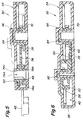
- FIGURES 5 and 6 are cross-sectional views taken on lines 5-5 and 6-6 of FIGURE 4, respectively.
- Referring now to the drawings wherein the showings are for the purposes of illustrating the preferred embodiment of the invention only and not for purposes of limiting same, FIGURE 1 shows the overall arrangement of a
temperature control system 10 for controlling the temperature of air supplied to the passenger compartment of a motor vehicle. In the system illustrated, a rotary, manuallyoperable control knob 12 is mechanically, drivingly interconnected with a vent damper orblend door 14 that acts to selectively blend or mix outside air and temperature modified air to produce a desired output stream that is connected to the vehicle passenger compartment. In the subject embodiment, thecontrol knob 12 is connected through a worm andspur gear assembly 16 with an input orcontrol pulley 18 of a pull-pullcable drive system 20. The output of the pull-pull cable system comprises and output or vent pulley 22 (see FIGURE 3) that is mounted in a suitable housing 24 that forms part of a drive means andgear system 30 that will subsequently be discussed and described in detail. - The particular form of interconnection between the
rotary input knob 12 and thecontrol pulley 18 could be of a variety of different types and the worm and spur gear combination shown is merely for illustration purposes. Likewise, with respect to the pull-pull cable system 20, this could also be a variety of specific, well known constructions, for example, it could be generally as shown in U.S. Patent No. 5,235,866 of August 17, 1993 "Rotary Temperature Control Device" and assigned to one of the assignees of the subject application. - The drive means and
gear system 30 which provides the drive connection between the pull-pullcable drive system 20 and theoutput shaft 14a which operates theblend door 14 is particularly designed to produce a predetermined, generally non-linear movement relationship between the rotary movement of thecontrol pulley 12 and the rotary movement of theoutput shaft 14a to produce a generally linear relationship between the rotary movement of thecontrol pulley 12 and the temperature of the blended air stream supplied to the passenger compartment throughout a major portion of the rotary movement of the control pulley. As will subsequently be described in some detail, this is accomplished through the use of variable ratio, non-circular gearing to compensate for the non-linear relationship between the blend door movement and the mix ratio produced between the blend air streams. The preferred form forsystem 30 can best be understood by reference to FIGURES 2 - 6. As particularly shown in FIGURES 2 and 3,assembly 30 includes an outer housing that generally comprises alower housing component 32 and a cover orupper housing component 34 that is suitably joined thereto in any convenient manner, such as by mechanical fasteners, welding, or the like. Thelower housing component 32 includes a base orbottom wall 36 and an integral, upwardly extendingperipheral wall 38 which defines agear chamber 40. Thebottom wall 36 extends laterally beyond thewall 38 in theportion 42 shown to provide a mounting plate and to underlie the cables of pull-pull system 20 that enter into thegear chamber 40 and connect with thevent pulley 22. - The housing components could be formed from a variety of different materials but, in the preferred embodiment, are molded plastic components formed from a relatively high strength plastic such as ABS.
- Referring again to the
lower housing component 30, it will be noted that threecircular posts bottom wall 36. Thefirst post 44 is arranged to receive thevent pulley 22 and is generally aligned between the pair of openings 50 - 52 that provide receiving elements that are adapted to clamp about the outer sheaths of the pull-pull cables. The pull cables are, in turn, received in asuitable guide groove 56 formed in the outer surface of thevent pulley 22. As can be appreciated, thecentral hub 22a and through opening 22b of the vent pulley are sized and related to the first post to allow free, but smooth rotary movement therebetween. - Driven directly from the vent pulley is a first
non-circular gear 60 that is mounted for direct rotation with thevent pulley 22 about the axis defined bypost 44. In its preferred form, the firstnon-circular gear 60 and thevent pulley 22 are molded as a single, unitary element with thenon-circular gear 60 positioned beneath thevent pulley 22 as best seen in FIGURES 3 and 6. - It should, of course, be understood that the various gears and pulleys could be formed from a variety of different material but, in the subject embodiment, are preferably molded from a plastic or resinous material such as type PA66 nylon.
- Referring again to FIGURES 3 and 4, it will be seen that a second
non-circular gear 66 is arranged to cooperate with the firstnon-circular gear 60 and is arranged and designed so as to have a central through opening 66b for rotation on thesecond post 46. The second non-circular gear 66is designed such that it is mounted in horizontal alignment with the firstnon-circular gear 60. Positioned immediately above and rotatable about the same vertical axis defined by thesecond post 46 is acircular pinion gear 70 that is drivingly connected directly with the secondnon-circular gear 66. It is, of course, mounted for rotation about the axis defined by the second post. In the subject embodiment, thenon-circular gear 66 and thepinion gear 70 are molded as a single unitary structure. - The
pinion gear 70 is, in turn, drivingly engaged with asector gear 74 mounted for rotation on thethird post 48. As best seen in FIGURE 5, thesector gear 74 is arranged so as to rest within thethird post 48 and is provided with a downwardly extending flange 74a that defines aslot 74b that receives thethird post 44. Thecentral sleeve portion 74c of thesector gear 74 extends upwardly through thecover 34 of the housing. It should be noted that the central portion of thesleeve 74c is provided with a throughopening 74d and is adapted to drivingly engage through suitable keying with theoutput shaft 14a that carries the blend door. - Referring more particularly to FIGURES 5 and 6, it will be noted that the
cover member 34, in addition to providing the throughopening 80 which engages about the upper end of sleeve 4c, is further provided withcylindrical recesses second posts output pulley 22 in place thereon and to further rigidify the assembly. As previously discussed, the non-circular gears 60, 66 are designed and arranged so as to provide a drive connection between the vent pulley and the output shaft to produce a generally non-linear relationship between rotary movement of the control pulley and rotary movement of the output shaft. This non-linear relationship is selected and designed to desirably provide a generally linear relationship between the rotary movement of the control pulley and the temperature of the resulting blended or mixed air stream throughout a major portion of the rotary movement of the control pulley. The actual relationship can be slightly non-linear throughout various portions of the control range if desired to better control the input forces required in the manual rotary knob. This, of course, varies with each individual system and modification of the gear relationships can modify this facet of the input movement. - The design of the required non-circular gears is basically an empirical process using well known techniques. In the subject control system, the design parameters are controlled by the characteristics of the heating system to which the control system is applied. The first step of the design process is obtaining a plot of output blended air temperature versus blend door angular position and a plot of blend door torque versus bend door angular position. With that data, it is then possible, using known techniques, to determine the theoretical pitch curve that produces a linear temperature output. Based on the theoretical pitch curve, the theoretical control knob loads can be determined based on the ratios of the non-circular gears. The pitch curve can, of course, be modified to achieve an acceptable compromise between control knob load and temperature curve.
- After the desired theoretical pitch curve is developed, the gear teeth for the first gear are created on the curve and the teeth for the second gear are created to match the teeth of the first gear.
- As previously mentioned, the actual drive connection between the knob and the pull-pull cable system can vary from that illustrated. In addition, it should be understood that various types of detent mechanisms could be included in this drive to provide a more definite feedback to the operator and improve the overall feel and functioning of the device.
- As can be seen from the foregoing discussions, the subject invention allows improved temperature control relationships and allows the input movement to be directly related to the system output temperature.
- The invention has been described with reference to the preferred embodiment. Obviously, modifications and alterations will occur to others upon a reading and understanding of this specification. It is intended to include all such modifications and alterations insofar as they come within the scope of the appended claims or the equivalents thereof.
Claims (13)
- A rotary temperature control system comprising:a manually operable rotary control knob;a control pulley operatively connected with the control knob for selective rotation thereby;a vent pulley;flexible cable means extending from the control pulley to the vent pulley for producing rotary movement of the vent pulley in response to rotary movement of the control pulley;a rotary output shaft for driving a blend door that controls the output temperature of a blended air stream; and,drive means including non-circular gears providing a drive connection between the vent pulley and the output shaft for producing a predetermined generally non-linear relationship between rotary movement of the control pulley and rotary movement of the output shaft to produce a generally linear relationship between the rotary movement of the control pulley and the temperature of the air stream throughout a major Portion of the rotary movement of the control pulley.
- The rotary temperature control system of claim 1 wherein the drive means includes a sector gear rotated by the vent pulley.
- The rotary temperature control system of claim 2 wherein the drive means further includes at least first and second non-circular gears engaged and positioned to transmit rotary movement from the vent pulley to the rotary output shaft.
- The rotary temperature control system of claim 3 wherein the vent pulley and one of the first and second non-circular gears are mounted for rotation about a common axis.
- The rotary temperature control system of claim 3 wherein one of the first and second non-circular gears and the vent pulley is mounted for rotation about an axis spaced from the axis of the rotary output shaft.
- The rotary temperature control system as defined in claim 1 wherein the vent pulley and the drive means including the non-circular gears is mounted in a common housing.
- The rotary temperature control system as defined in claim 6 wherein there are at least two non-circular gears carried in said housing for rotation about separate first and second parallel axes.
- The rotary temperature control system as defined in claim 6 wherein said vent pulley is formed integrally with one of the non-circular gears.
- The rotary temperature control system as defined in claim 7 wherein the output shaft is rotated about a third axis parallel to the first and second parallel axes.
- The rotary temperature control system as defined in claim 9 wherein the drive means includes cooperating circular gears driving between the output shaft and at least one of the non-circular gears.
- For use in a rotary temperature control system wherein a vent pulley is drivingly rotated from a manually operable rotary control knob, a drive assembly for connecting the vent pulley to a blend door that controls the output temperature of a blended air stream, said drive assembly comprising:a rotary output shaft for connection to the blend door;a housing into which the output shaft extends; and,drive means in the housing including a first and second interengaged non-circular gears rotatable about spaced first and second parallel axes and providing a drive connection between the vent pulley and the output shaft for producing a predetermined generally non-linear relationship between the rotary movement of the control pulley and the temperature of the air stream throughout a major portion of the rotary movement of the control pulley.
- The drive assembly as set forth in claim 11 wherein the vent pulley is mounted in the housing in direct rotary connection with one of the first and second non-circular gears.
- The drive assembly as set forth in claim 12 wherein the output shaft is rotatable about an axis parallel to the axes of rotation of the non-circular gears.
Applications Claiming Priority (2)
| Application Number | Priority Date | Filing Date | Title |
|---|---|---|---|
| US08/661,936 US5881994A (en) | 1996-06-11 | 1996-06-11 | Variable temperature control system for vehicles |
| US661936 | 1996-06-11 |
Publications (3)
| Publication Number | Publication Date |
|---|---|
| EP0812713A2 true EP0812713A2 (en) | 1997-12-17 |
| EP0812713A3 EP0812713A3 (en) | 1998-07-29 |
| EP0812713B1 EP0812713B1 (en) | 2001-10-31 |
Family
ID=24655716
Family Applications (1)
| Application Number | Title | Priority Date | Filing Date |
|---|---|---|---|
| EP97109513A Expired - Lifetime EP0812713B1 (en) | 1996-06-11 | 1997-06-11 | Variable temperature control system for vehicles |
Country Status (3)
| Country | Link |
|---|---|
| US (2) | US5881994A (en) |
| EP (1) | EP0812713B1 (en) |
| DE (1) | DE69707755T2 (en) |
Cited By (4)
| Publication number | Priority date | Publication date | Assignee | Title |
|---|---|---|---|---|
| FR2803055A1 (en) * | 1999-12-23 | 2001-06-29 | Renault | DEVICE FOR CONTROLLING THE MOVEMENT OF A MOTOR VEHICLE |
| EP1177923A2 (en) | 2000-08-02 | 2002-02-06 | Valeo Klimasysteme GmbH | Adjusting mechanism |
| EP1086839A4 (en) * | 1999-04-16 | 2005-03-09 | Mitsubishi Heavy Ind Ltd | Air mix damper device and vehicle air conditioner |
| EP1598222A3 (en) * | 2004-05-18 | 2006-10-25 | Valeo Klimasysteme GmbH | Coupling device for a heating, cooling and/or ventilation system |
Families Citing this family (20)
| Publication number | Priority date | Publication date | Assignee | Title |
|---|---|---|---|---|
| US6135415A (en) * | 1998-07-30 | 2000-10-24 | Siemens Canada Limited | Exhaust gas recirculation assembly |
| KR20000013274A (en) * | 1998-08-06 | 2000-03-06 | 윤종용 | Improved alarm method of mobile phone |
| FR2782299B1 (en) * | 1998-08-12 | 2000-11-10 | Valeo Electronique | CONTROL PANEL WITH DOUBLE ROTARY CONTROL FOR MOTOR VEHICLE |
| JP2004189050A (en) * | 2002-12-10 | 2004-07-08 | Calsonic Kansei Corp | Door controller for air conditioning system |
| JP2005145190A (en) * | 2003-11-13 | 2005-06-09 | Denso Corp | Air conditioner for vehicle |
| DE10355247A1 (en) * | 2003-11-26 | 2005-06-30 | Volkswagen Ag | Air flow channel`s air quantity adjustment device for air-conditioning system, has operating device whose manual movement is activated by actuator, to adjust air deflector and flow cross-section contraction device to adjust flow via channel |
| DE102004030821B4 (en) * | 2004-06-25 | 2015-06-03 | Valeo Klimasysteme Gmbh | Transmission mechanism for a control flap |
| US20090156343A1 (en) * | 2007-12-14 | 2009-06-18 | Stevenson Mark W | Force multiplying control cable system |
| US20100192721A1 (en) * | 2009-01-30 | 2010-08-05 | Delphi Technologies, Inc. | Pull-Pull Cable Assembly Having a Self-Adjusting Cable Tensioning Assembly |
| US8403734B2 (en) * | 2009-02-20 | 2013-03-26 | Deere & Company | Vent control system |
| US9410629B2 (en) * | 2009-03-13 | 2016-08-09 | Illinois Tool Works, Inc. | Vehicle vent valve assembly |
| DE102009034839A1 (en) | 2009-07-27 | 2011-02-03 | Minebea Co., Ltd. | Control device for a valve of an air conditioner of a motor vehicle |
| KR101534867B1 (en) * | 2009-11-11 | 2015-07-07 | 기아자동차주식회사 | Apparatus for integrated control of HVAC for vehicle |
| DE102011112476A1 (en) * | 2011-09-05 | 2013-03-07 | Epcos Ag | Component and method for manufacturing a device |
| US8956207B2 (en) * | 2011-12-13 | 2015-02-17 | Controlled Holdings, Llc | Barometric relief air zone damper |
| DE102012007745B4 (en) | 2012-04-18 | 2023-07-13 | Valeo Klimasysteme Gmbh | Control element for a vehicle ventilation and/or air conditioning system, control assembly and vehicle ventilation and/or air conditioning system |
| US20140000397A1 (en) * | 2012-06-29 | 2014-01-02 | Visteon Global Technologies, Inc. | Constant to variable gear pitch for temperature door rotation |
| GB2514377A (en) * | 2013-05-21 | 2014-11-26 | Johnson Electric Sa | Actuator with progressive gear |
| US11660930B2 (en) * | 2019-10-14 | 2023-05-30 | Denso International America, Inc. | Actuator assembly |
| DE102020120614B4 (en) * | 2020-08-05 | 2025-05-28 | Dr. Ing. H.C. F. Porsche Aktiengesellschaft | Ventilation flap of a fairing part, namely a front part or a rear part, of a vehicle |
Family Cites Families (12)
| Publication number | Priority date | Publication date | Assignee | Title |
|---|---|---|---|---|
| US1501340A (en) * | 1920-05-24 | 1924-07-15 | Horace L Hirschler | Control mechanism |
| US2220431A (en) * | 1939-02-27 | 1940-11-05 | Adam J Strehs | Well cap |
| US2583050A (en) * | 1945-09-26 | 1952-01-22 | Everlasting Valve Co | Valve operating mechanism |
| US3823617A (en) * | 1972-04-28 | 1974-07-16 | Aqua Marine Mfg Ltd | Steering system |
| FR2357951A1 (en) * | 1976-07-05 | 1978-02-03 | Renault | SINGLE LEVER OPERATION DEVICE, ESPECIALLY FOR AIR CONDITIONING CONTROLS |
| US4509387A (en) * | 1982-08-02 | 1985-04-09 | Teleflex Incorporated | Actuator assembly for remotely controlling a valve |
| JPS601016A (en) * | 1983-06-20 | 1985-01-07 | Mitsubishi Electric Corp | Automotive air conditioner |
| DE3409260A1 (en) * | 1983-10-10 | 1985-04-11 | Preh, Elektrofeinmechanische Werke Jakob Preh Nachf. Gmbh & Co, 8740 Bad Neustadt | OPERATING UNIT |
| US4535932A (en) * | 1984-06-11 | 1985-08-20 | Carrier Corporation | Actuator for a heating/cooling diffuser |
| DE3434302A1 (en) * | 1984-08-01 | 1986-02-13 | Preh, Elektrofeinmechanische Werke Jakob Preh Nachf. Gmbh & Co, 8740 Bad Neustadt | OPERATING UNIT |
| JP2594937Y2 (en) * | 1990-02-19 | 1999-05-24 | 株式会社 東海理化電機製作所 | Heater control unit |
| US5235866A (en) * | 1992-08-05 | 1993-08-17 | Handy And Harman Automotive Group, Inc. | Rotary temperature control device |
-
1996
- 1996-06-11 US US08/661,936 patent/US5881994A/en not_active Expired - Lifetime
-
1997
- 1997-06-11 EP EP97109513A patent/EP0812713B1/en not_active Expired - Lifetime
- 1997-06-11 DE DE69707755T patent/DE69707755T2/en not_active Expired - Fee Related
-
1998
- 1998-06-26 US US09/105,164 patent/US6031226A/en not_active Expired - Lifetime
Cited By (5)
| Publication number | Priority date | Publication date | Assignee | Title |
|---|---|---|---|---|
| EP1086839A4 (en) * | 1999-04-16 | 2005-03-09 | Mitsubishi Heavy Ind Ltd | Air mix damper device and vehicle air conditioner |
| FR2803055A1 (en) * | 1999-12-23 | 2001-06-29 | Renault | DEVICE FOR CONTROLLING THE MOVEMENT OF A MOTOR VEHICLE |
| EP1177923A2 (en) | 2000-08-02 | 2002-02-06 | Valeo Klimasysteme GmbH | Adjusting mechanism |
| DE10037733A1 (en) * | 2000-08-02 | 2002-02-14 | Valeo Klimasysteme Gmbh | adjustment |
| EP1598222A3 (en) * | 2004-05-18 | 2006-10-25 | Valeo Klimasysteme GmbH | Coupling device for a heating, cooling and/or ventilation system |
Also Published As
| Publication number | Publication date |
|---|---|
| US6031226A (en) | 2000-02-29 |
| DE69707755D1 (en) | 2001-12-06 |
| EP0812713A3 (en) | 1998-07-29 |
| EP0812713B1 (en) | 2001-10-31 |
| US5881994A (en) | 1999-03-16 |
| DE69707755T2 (en) | 2002-08-08 |
Similar Documents
| Publication | Publication Date | Title |
|---|---|---|
| US5881994A (en) | Variable temperature control system for vehicles | |
| EP0653028B1 (en) | Rotary temperature control device | |
| DE10024907A1 (en) | Drive unit | |
| US5245886A (en) | Rotary temperature mechanism | |
| EP0397899B1 (en) | Heat and air conditioning device for an automotive vehicle | |
| DE19537504A1 (en) | Vehicle side-door fitted out with various components and electronic controller | |
| CA1301828C (en) | Servoactuator with feedback and method of calibrating same | |
| EP0575861B1 (en) | A gear control system for motor vehicles | |
| DE3914627A1 (en) | OPERATING DEVICE FOR HEATING, AIR, AND / OR AIR CONDITIONING OF A MOTOR VEHICLE | |
| JPH10119540A (en) | Variable temperature controller for vehicle | |
| US6405933B1 (en) | Control device for a system for distributing an airflow in a vehicle | |
| US4331313A (en) | 6-Way split bench seat adjuster | |
| JPH09195628A (en) | Vehicle door component mounting structure and vehicle door assembly method | |
| EP0606862B1 (en) | Arrangement of actuators | |
| EP0803388A2 (en) | Control unit for a heating device in a vehicle | |
| US7002316B2 (en) | Vehicle HVAC door with enclosed motor | |
| DE19845455C2 (en) | Device for actuating an air flow control element of a ventilation, heating or air conditioning system of a motor vehicle | |
| JP4239433B2 (en) | Air conditioner for vehicles | |
| EP1260391B1 (en) | Decentral and modular multifunctional group for a vehicle air duct | |
| EP0834790B1 (en) | Interfitting structure for control knob and shaft | |
| EP0482219B1 (en) | Control unit for adjusting the apparatus for heating air conditioning and/or ventilation in motor vehicles | |
| DE19861427B4 (en) | Air flow control element operating device for vehicle, in which operating element, transmission shaft and control element are linked via raising and lowering transmissions | |
| KR0133374Y1 (en) | Cable drive device of airconditioner panel for a vehicle | |
| DE19522787A1 (en) | Car window worm drive with rope drum | |
| KR200221971Y1 (en) | Actuator of Aircon for Vehicle |
Legal Events
| Date | Code | Title | Description |
|---|---|---|---|
| PUAI | Public reference made under article 153(3) epc to a published international application that has entered the european phase |
Free format text: ORIGINAL CODE: 0009012 |
|
| AK | Designated contracting states |
Kind code of ref document: A2 Designated state(s): DE ES FR GB IT |
|
| PUAL | Search report despatched |
Free format text: ORIGINAL CODE: 0009013 |
|
| AK | Designated contracting states |
Kind code of ref document: A3 Designated state(s): AT BE CH DE DK ES FI FR GB GR IE IT LI LU MC NL PT SE |
|
| 17P | Request for examination filed |
Effective date: 19980923 |
|
| AKX | Designation fees paid |
Free format text: DE ES FR GB IT |
|
| RBV | Designated contracting states (corrected) |
Designated state(s): DE ES FR GB IT |
|
| 17Q | First examination report despatched |
Effective date: 19991101 |
|
| GRAG | Despatch of communication of intention to grant |
Free format text: ORIGINAL CODE: EPIDOS AGRA |
|
| GRAG | Despatch of communication of intention to grant |
Free format text: ORIGINAL CODE: EPIDOS AGRA |
|
| GRAH | Despatch of communication of intention to grant a patent |
Free format text: ORIGINAL CODE: EPIDOS IGRA |
|
| RAP1 | Party data changed (applicant data changed or rights of an application transferred) |
Owner name: VISTEON GLOBAL TECHNOLOGIES, INC. Owner name: TRW INC. |
|
| GRAH | Despatch of communication of intention to grant a patent |
Free format text: ORIGINAL CODE: EPIDOS IGRA |
|
| GRAA | (expected) grant |
Free format text: ORIGINAL CODE: 0009210 |
|
| AK | Designated contracting states |
Kind code of ref document: B1 Designated state(s): DE ES FR GB IT |
|
| PG25 | Lapsed in a contracting state [announced via postgrant information from national office to epo] |
Ref country code: IT Free format text: LAPSE BECAUSE OF FAILURE TO SUBMIT A TRANSLATION OF THE DESCRIPTION OR TO PAY THE FEE WITHIN THE PRESCRIBED TIME-LIMIT;WARNING: LAPSES OF ITALIAN PATENTS WITH EFFECTIVE DATE BEFORE 2007 MAY HAVE OCCURRED AT ANY TIME BEFORE 2007. THE CORRECT EFFECTIVE DATE MAY BE DIFFERENT FROM THE ONE RECORDED. Effective date: 20011031 |
|
| REF | Corresponds to: |
Ref document number: 69707755 Country of ref document: DE Date of ref document: 20011206 |
|
| REG | Reference to a national code |
Ref country code: GB Ref legal event code: IF02 |
|
| ET | Fr: translation filed | ||
| PG25 | Lapsed in a contracting state [announced via postgrant information from national office to epo] |
Ref country code: ES Free format text: LAPSE BECAUSE OF FAILURE TO SUBMIT A TRANSLATION OF THE DESCRIPTION OR TO PAY THE FEE WITHIN THE PRESCRIBED TIME-LIMIT Effective date: 20020430 |
|
| PLBE | No opposition filed within time limit |
Free format text: ORIGINAL CODE: 0009261 |
|
| STAA | Information on the status of an ep patent application or granted ep patent |
Free format text: STATUS: NO OPPOSITION FILED WITHIN TIME LIMIT |
|
| 26N | No opposition filed | ||
| PGFP | Annual fee paid to national office [announced via postgrant information from national office to epo] |
Ref country code: DE Payment date: 20070629 Year of fee payment: 11 |
|
| PGFP | Annual fee paid to national office [announced via postgrant information from national office to epo] |
Ref country code: GB Payment date: 20070511 Year of fee payment: 11 |
|
| PGFP | Annual fee paid to national office [announced via postgrant information from national office to epo] |
Ref country code: FR Payment date: 20070605 Year of fee payment: 11 |
|
| GBPC | Gb: european patent ceased through non-payment of renewal fee |
Effective date: 20080611 |
|
| REG | Reference to a national code |
Ref country code: FR Ref legal event code: ST Effective date: 20090228 |
|
| PG25 | Lapsed in a contracting state [announced via postgrant information from national office to epo] |
Ref country code: DE Free format text: LAPSE BECAUSE OF NON-PAYMENT OF DUE FEES Effective date: 20090101 |
|
| PG25 | Lapsed in a contracting state [announced via postgrant information from national office to epo] |
Ref country code: GB Free format text: LAPSE BECAUSE OF NON-PAYMENT OF DUE FEES Effective date: 20080611 |
|
| PG25 | Lapsed in a contracting state [announced via postgrant information from national office to epo] |
Ref country code: FR Free format text: LAPSE BECAUSE OF NON-PAYMENT OF DUE FEES Effective date: 20080630 |