EP0811552B1 - Ship's rudder - Google Patents
Ship's rudder Download PDFInfo
- Publication number
- EP0811552B1 EP0811552B1 EP96115518A EP96115518A EP0811552B1 EP 0811552 B1 EP0811552 B1 EP 0811552B1 EP 96115518 A EP96115518 A EP 96115518A EP 96115518 A EP96115518 A EP 96115518A EP 0811552 B1 EP0811552 B1 EP 0811552B1
- Authority
- EP
- European Patent Office
- Prior art keywords
- rudder
- piston
- sliding
- fin
- pistons
- Prior art date
- Legal status (The legal status is an assumption and is not a legal conclusion. Google has not performed a legal analysis and makes no representation as to the accuracy of the status listed.)
- Expired - Lifetime
Links
- 229910000906 Bronze Inorganic materials 0.000 claims description 11
- 239000010974 bronze Substances 0.000 claims description 9
- KUNSUQLRTQLHQQ-UHFFFAOYSA-N copper tin Chemical compound [Cu].[Sn] KUNSUQLRTQLHQQ-UHFFFAOYSA-N 0.000 claims description 9
- 239000002184 metal Substances 0.000 claims description 7
- 229910052751 metal Inorganic materials 0.000 claims description 7
- 239000010935 stainless steel Substances 0.000 claims description 4
- 229910001220 stainless steel Inorganic materials 0.000 claims description 4
- XLYOFNOQVPJJNP-UHFFFAOYSA-N water Substances O XLYOFNOQVPJJNP-UHFFFAOYSA-N 0.000 claims description 4
- 239000004519 grease Substances 0.000 claims description 2
- 239000007788 liquid Substances 0.000 claims description 2
- 238000007789 sealing Methods 0.000 claims description 2
- 238000010276 construction Methods 0.000 description 4
- 238000013016 damping Methods 0.000 description 2
- 150000002739 metals Chemical class 0.000 description 2
- 238000012856 packing Methods 0.000 description 2
- 235000011837 pasties Nutrition 0.000 description 2
- 239000004952 Polyamide Substances 0.000 description 1
- 238000005299 abrasion Methods 0.000 description 1
- 238000005452 bending Methods 0.000 description 1
- 230000005540 biological transmission Effects 0.000 description 1
- 230000008878 coupling Effects 0.000 description 1
- 238000010168 coupling process Methods 0.000 description 1
- 238000005859 coupling reaction Methods 0.000 description 1
- 230000001419 dependent effect Effects 0.000 description 1
- 238000011161 development Methods 0.000 description 1
- 230000018109 developmental process Effects 0.000 description 1
- 230000000694 effects Effects 0.000 description 1
- 239000012212 insulator Substances 0.000 description 1
- 238000005461 lubrication Methods 0.000 description 1
- 238000004519 manufacturing process Methods 0.000 description 1
- 239000004033 plastic Substances 0.000 description 1
- 229920002647 polyamide Polymers 0.000 description 1
- 230000008439 repair process Effects 0.000 description 1
- 239000013535 sea water Substances 0.000 description 1
- 230000035939 shock Effects 0.000 description 1
Images


Classifications
-
- B—PERFORMING OPERATIONS; TRANSPORTING
- B63—SHIPS OR OTHER WATERBORNE VESSELS; RELATED EQUIPMENT
- B63H—MARINE PROPULSION OR STEERING
- B63H25/00—Steering; Slowing-down otherwise than by use of propulsive elements; Dynamic anchoring, i.e. positioning vessels by means of main or auxiliary propulsive elements
- B63H25/06—Steering by rudders
- B63H25/38—Rudders
- B63H25/381—Rudders with flaps
-
- B—PERFORMING OPERATIONS; TRANSPORTING
- B63—SHIPS OR OTHER WATERBORNE VESSELS; RELATED EQUIPMENT
- B63H—MARINE PROPULSION OR STEERING
- B63H25/00—Steering; Slowing-down otherwise than by use of propulsive elements; Dynamic anchoring, i.e. positioning vessels by means of main or auxiliary propulsive elements
- B63H25/06—Steering by rudders
- B63H25/38—Rudders
Definitions
- the invention relates to a rudder for seagoing vessels consisting of a main rudder and a rudder articulated to it via a pivot pin, by the main rudder positively guided fin, which with a Sliding piston linkage made from a fin formed Slide bearing is provided for a swing piston.
- a drive adjustable, multi-part flow body for control known from watercraft.
- This flow body consists of a main oar and a fin attached to it the main rudder is articulated. Adjust around the fin To be able to, this is provided with a control device, which from an adjacent to the articulation of Main rudder and fin on the top in the longitudinal direction of the Cantilevered support arm extending through the flow body with a longitudinal guide for a slide valve, the vertical end of which faces the main rudder The end of the pin is eccentric in one drive pulley rotatable about its vertical central axis is stored.
- a multi-part flow body with a control device for pivoting the fin-like part of the flow body created in its manufacture should be easy and effortless to use. Due to the small number of mechanical components used is a safe functioning of the control device guaranteed, however, in the event of wear the control and sliding device requires extensive work, because whole construction parts are then exchanged Need to become.
- the guide bushing is approximately horizontal and almost parallel to the rudder surface on the auxiliary rudder arranged while the drive rod rotatable on a is arranged behind the rudder axis and is of such a length that the cooperation between the drive rod and the guide bush in the event of a rudder deflection of 90 ° or more still works well.
- This rudder is essentially designed that a lateral turning of the rudder is then possible is when a trained with this ship rudder construction Ship lies in a lock to during the Do not pass through the drums of the lock gates to be damaged.
- the guide bush As a plain bearing, the guide bush has in its interior a slide pack on. Is it worn out and must be replaced, extensive work is required because about the sliding packing from the guide bush To be able to take out, either the fin from Main rudder to be removed from the guide bushing to be able to pull off the connecting rod, or the connecting rod must in its articulation area on the hull of this loosened and pulled out of the guide bush. Since the guide bush encloses the sliding packing with the wall is taking out the slide pack not possible from the guide bush up or down, but only by taking the joint apart the slide pack can be exposed.
- Every slide block should be in one recess limited at the bottom and open at the top in the wall surface of each fork arm of the plain bearing held and against unintentional pulling through a closing the upper opening of the recess and releasable cover plate be secured.
- This configuration enables movements with sufficient Degrees of freedom by using a hinge pin between the two pistons in the housing be obtained so that movements in an angular range of ⁇ 90 ° are possible, whereas the known ones Systems rigidly designed by the specified angle of 90 ° are.
- Another advantage is there in that after loosening the hinge connection between the two pistons in the longitudinal direction of the piston, i.e. in vertical and horizontal direction from the on the hull and pulled out housings attached to the fin can be. In this way, repairs are effortless and feasible without removing the fin.
- Both pistons are preferred, namely the pivoting piston and the piston designed as a pivot pin connected to each other via a hinge pin, the one creates a safe and structurally simple coupling.
- Both pistons are preferably made of stainless steel and are Slidably arranged in bronze alloy bushings.
- the bronze fill for the cylindrical one Pistons each arranged in a housing shell Rifle is sealed, the seal preferably consists of a pasty two-component metal, which is also known as "Belzona-R metal". That metal has the quality of known metals after hardening and is basically for sealing joints and as an insulator suitable between black and fret metals.
- Water is preferably all moving parts protected by O-rings, so that a closed lubrication system arises.
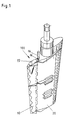
- the rudder shown in Fig. 1 consists of a main rudder 20 with a pivotally arranged thereon and positively guided fin 10, which with a sliding pivot piston linkage 100 is provided, which in Fig. 2 to 6 is shown in more detail.
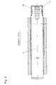
- This is made up of a horizontally arranged stainless steel piston 11, which in one Bearing housing 12 is slidably disposed, the inner shell is lined with a bronze fill 13.
- the piston part protruding from the housing is over a Hinge pin 14 with a vertically movable stainless steel piston 15 connected, which in turn in a bearing housing 16 is slidably arranged, also with a bronze fill 17 is lined.
- the hinge pin 14 ensures that there is also a deviation can be compensated from the 90 ° position.
- the horizontal bolt is tied to the fin 10 while the vertical piston 15 represents the connection to the ship's hull.
- the each along the longitudinal axis of the sliding piston 11 and 15 formed upper and lower edge of the bronze fill 13 and 17 can be conical, with the each tapered outer interfaces of the the resulting free space is provided with a seal, in particular from a pasty two-component metal.
- the bolt 14 is together with other connecting elements, such as Locking screws etc. to the outside through locking plates covered.
- a Pad 30 from a gaseous medium, such as air, or formed from a liquid medium such as water (Fig.3).
- the pistons and / or sliding surfaces are lubricated with water or grease, causing the sliding ability of moving parts is increased.
Landscapes
- Chemical & Material Sciences (AREA)
- Engineering & Computer Science (AREA)
- Combustion & Propulsion (AREA)
- Mechanical Engineering (AREA)
- Ocean & Marine Engineering (AREA)
- Pivots And Pivotal Connections (AREA)
- Actuator (AREA)
- Sliding-Contact Bearings (AREA)
- Earth Drilling (AREA)
- Physical Or Chemical Processes And Apparatus (AREA)
- Revetment (AREA)
- Percussive Tools And Related Accessories (AREA)
- Bridges Or Land Bridges (AREA)
Description
Die Erfindung betrifft ein Ruder für Seeschiffe, bestehend aus einem Hauptruder und einer an diesem über einen Anlenkungsbolzen angelenkten, durch das Hauptruder zwangsgeführten Flosse, die mit einer Gleitkolbenanlenkung aus einem an der Flosse ausgebildeten Gleitlager für einen Schwenkkolben versehen ist.The invention relates to a rudder for seagoing vessels consisting of a main rudder and a rudder articulated to it via a pivot pin, by the main rudder positively guided fin, which with a Sliding piston linkage made from a fin formed Slide bearing is provided for a swing piston.
Für die Anlenkung der Flosse an das Hauptruder von Flossenrudern für Seeschiffe sind bereits die verschiedensten Lösungen vorgeschlagen worden.For the linkage of the fin to the main rudder of fin oars for ocean-going ships are the most diverse Solutions have been proposed.
So ist nach der DE-U-7 829 008 ein mittels eines Antriebes verstellbarer, mehrteiliger Strömungskörper zum Steuern von Wasserfahrzeugen bekannt. Dieser Strömungskörper besteht aus einem Hauptruder und einer Flosse, die an dem Hauptruder angelenkt ist. Um die Flosse verstellen zu können, ist diese mit einer Steuereinrichtung versehen, die aus einem benachbart zur Gelenkverbindung von Hauptruder und Flosse obenseitig in Längsrichtung des Strömungskörpers verlaufenden, auskragenden Tragarm mit einer Längsführung für einen Gleitschieber besteht, dessen dem Hauptruder zugekehrtes Ende einen senkrechten Zapfen trägt, der mit seinem Ende exzentrisch in einer um ihre senkrechte Mittelachse verdrehbare Antriebsscheibe gelagert ist. Aufgrund dieser Ausgestaltung wird ein mehrteiliger Strömungskörper mit einer Steuereinrichtung zum Verschwenken des flossenartigen Teils des Strömungskörpers geschaffen, der in seiner Herstellung einfach und mühelos bedienbar sein soll. Aufgrund der geringen Anzahl an verwendeten mechanischen Bauteilen ist zwar eine sichere Funktionsweise der Steuereinrichtung gewährleistet, jedoch sind bei einem Verschleiß der Steuer- und Gleiteinrichtung aufwendige Arbeiten erforderlich, da ganze Konstruktionsteile dann ausgetauscht werden müssen.So is according to DE-U-7 829 008 by means of a drive adjustable, multi-part flow body for control known from watercraft. This flow body consists of a main oar and a fin attached to it the main rudder is articulated. Adjust around the fin To be able to, this is provided with a control device, which from an adjacent to the articulation of Main rudder and fin on the top in the longitudinal direction of the Cantilevered support arm extending through the flow body with a longitudinal guide for a slide valve, the vertical end of which faces the main rudder The end of the pin is eccentric in one drive pulley rotatable about its vertical central axis is stored. Because of this configuration, a multi-part flow body with a control device for pivoting the fin-like part of the flow body created in its manufacture should be easy and effortless to use. Due to the small number of mechanical components used is a safe functioning of the control device guaranteed, however, in the event of wear the control and sliding device requires extensive work, because whole construction parts are then exchanged Need to become.
Eine weitere Schiffsruderkonstruktion der eingangs erwähnten Gattung für ein Schiff mit einer wenigstens teilweise mit einem Mantel versehenen Schraube mit einem an dem hinteren Rand des Hauptruders angelenkten Hilfsruder, das mit einem Bedienungsmechanismus verbunden ist, der eine in einer Führungsbuchse verschiebbare Treibstange enthält und in einer zu der Ruderachse ungefähr senkrechten Ebene um einen hinter dieser liegenden Drehpunkt mit dem Schiffsrumpf drehbar verbunden ist, ist durch die DE-A-2 353 934 bekannt. Bei dieser Schiffsruderkonstruktion ist die Führungsgbuchse ungefähr horizontal und nahezu parallel zu der Ruderfläche auf dem Hilfsruder angeordnet, während die Treibstange drehbar auf einer hinter der Ruderachse angeordneten Achse gelagert ist und eine solche Länge hat, daß die Zusammenarbeit zwischen der Treibstange und der Führungsbuchse bei einem Ruderausschlag von 90° oder mehr nach wie vor gut funktioniert. Dieses Schiffsruder ist im wesentlichen so konstruiert, daß ein Querstellen des Ruders insbesondere dann möglich ist, wenn ein mit dieser Schiffsruderkonstruktion ausgebildetes Schiff in einer Schleuse liegt, um während des Durchschleusens nicht von dem Drempel der Schleusentore beschädigt zu werden.Another ship rudder construction of the one mentioned at the beginning Type for a ship with at least one partially covered with a screw with a auxiliary rudder articulated on the rear edge of the main rudder, which is connected to an operating mechanism the one driving rod that can be moved in a guide bush contains and in an approximately perpendicular to the rudder axis Plane around a pivot point behind it is rotatably connected to the hull is through the DE-A-2 353 934 known. With this ship rudder construction the guide bushing is approximately horizontal and almost parallel to the rudder surface on the auxiliary rudder arranged while the drive rod rotatable on a is arranged behind the rudder axis and is of such a length that the cooperation between the drive rod and the guide bush in the event of a rudder deflection of 90 ° or more still works well. This rudder is essentially designed that a lateral turning of the rudder is then possible is when a trained with this ship rudder construction Ship lies in a lock to during the Do not pass through the drums of the lock gates to be damaged.
Die Führung und Lagerung der einendseitig am Schiffsrumpf gelagerten Treibstange zur Steuerung der Flosse erfolgt mittels der Führungsbuchse, die waagerecht liegend im oberen Bereich der Flosse an dieser befestigt ist und durch die die Treibstange hindurchgeführt ist.The management and storage of the one-sided on the hull mounted drive rod to control the fin by means of the guide bush, which lies horizontally in the upper area of the fin is attached to this and through which the drive rod is passed.
Als Gleitlager weist die Führungsbuchse in ihrem Innenraum eine Gleitpackung auf. Ist diese verschlissen und muß sie ausgetauscht werden, so sind umfassende Arbeiten erforderlich, denn um die Gleitpackung aus der Führungsgbuchse herausnehmen zu können, muß entweder die Flosse vom Hauptruder abgenommen werden, um die Führungsbuchse von der Treibstange abziehen zu können, oder die Treibstange muß in ihrem Anlenkungsbereich am Schiffsrumpf von diesem gelöst und aus der Führungsbuchse herausgezogen werden. Da die Führungsbuchse die Gleitpackung wandungsumschliessend aufnimmt, ist ein Herausnehmen der Gleitpackung aus der Führungsbuchse nach oben oder unten nicht möglich, sondern erst durch ein Auseinandernehmen der Gelenkverbindung kann die Gleitpackung freigelegt werden.As a plain bearing, the guide bush has in its interior a slide pack on. Is it worn out and must be replaced, extensive work is required because about the sliding packing from the guide bush To be able to take out, either the fin from Main rudder to be removed from the guide bushing to be able to pull off the connecting rod, or the connecting rod must in its articulation area on the hull of this loosened and pulled out of the guide bush. Since the guide bush encloses the sliding packing with the wall is taking out the slide pack not possible from the guide bush up or down, but only by taking the joint apart the slide pack can be exposed.
Alle bekannten Lösungen haben jedoch gemeinsam, daß die besonders leicht verschleißbaren Teile der Anlenkung zur Zwangsführung der Flosse nur mit einem hohen Kostenaufwand und überwiegend in Unterwasserarbeiten ausgetauscht werden können.However, all known solutions have in common that the parts of the linkage that are particularly easy to wear to force the fin only at a high cost and mostly exchanged in underwater work can be.
Um bei einem aus einem Hauptruder mit einer angelenkten und zwangsgeführten Flosse bestehenden Ruder das Gleitlager der Flosse für den einendig am Schiffsrumpf angelenkten Schwenkbolzen so auszubilden, daß ein müheloses Austauschen der Verschleißteile auch durch ungeschultes Personal ohne Zuhilfenahme von Hebewerkzeugen und ohne Durchführung von Unterwasserarbeiten möglich ist, und darüber hinaus eine Zwangsführung der Flosse in Abhängigkeit von der Winkelstellung des Hauptruders bei ausschließlicher Kraftübertragung in der Horizontalen zu ermöglichen, wird in der EP-A- 0 051 822 B1 vorgeschlagen, das Gleitlager gabelförmig auszubilden und an den einander zugekehrten Wandflächen seiner beiden Gabelarme austauschbare Gleitklötze aus Kunststoffen, insbesondere Polyamid, zu verwenden. Jeder Gleitklotz soll in einer nach unten begrenzten und nach oben offenen Ausnehmung in der Wandfläche eines jeden Gabelarmes des Gleitlagers gehalten und gegen ein unbeabsichtigtes Abziehen durch eine die obere Öffnung der Ausnehmung verschließende und lösbare Abdeckplatte gesichert sein.To one with a hinged main rudder and positively driven fin existing rudder the slide bearing the fin for the one-hinged to the hull Form pivot pin so that an effortless Exchange of wear parts also by untrained Personnel without the aid of lifting tools and without Implementation of underwater work is possible, and in addition, a dependent guidance of the fin from the angular position of the main rudder at exclusive Power transmission in the horizontal too enable is proposed in EP-A-0 051 822 B1, the fork bearing form a fork and on each other facing wall surfaces of his two fork arms interchangeable plastic sliding blocks, in particular Polyamide. Every slide block should be in one recess limited at the bottom and open at the top in the wall surface of each fork arm of the plain bearing held and against unintentional pulling through a closing the upper opening of the recess and releasable cover plate be secured.
In Einzelfällen ist bei einer solchen Ausführungsform im Inneren der Lager ein unerwünschter hoher Kantendruck festzustellen, der zu übermäßigem Verschleiß und Abrieb und bisweilen zur Lockerung der Bronzeausfütterung am Scharnier führt. Auch können Schwingungen bei zu großem Spiel in dem Rudersystem die Scharnierhaltebolzen lockern, insbesondere dann, wenn sie nicht korrekt befestigt sind.In individual cases, such an embodiment an undesirable high edge pressure inside the bearings notice of excessive wear and abrasion and sometimes to loosen the bronze lining leads on the hinge. Vibrations can also occur if they are too large Loosen the hinge retaining bolts in the rudder system, especially if they are not properly attached.
Es ist Aufgabe der vorliegenden Erfindung, das eingangs genannte System dahingehend zu verbessern, daß der genannte Kantendruck minimiert und alle Teile so miteinander verbunden sind, daß Bewegungen mit ausreichenden Freiheitsgraden möglich sind. Hierdurch sollen die Lageroberflächen geschont und der Verschleiß entsprechend minimiert werden.It is an object of the present invention to begin with improve the system in such a way that the said Edge pressure minimized and all parts so together are linked to movements with sufficient degrees of freedom possible are. This should make the bearing surfaces spared and wear minimized accordingly become.
Diese Aufgabe wird erfindungsgemäß bei dem eingangs genannten Ruder dadurch gelöst, daß auch der Anlenkungsbolzen als ein in einem Gleitlager ausgebildeter Kolben ausgebildet ist. Durch diese Maßnahme erhält das Ruder bzw. dessen bewegliche Teile eine weitgehende Schaffung von Freiheitsgraden, die gewährleistet, daß keine Lageroberfläche durch die Wirkung hochbelasteter Kanten stärker als nötig belastet wird.This object is achieved according to the invention in the aforementioned Rudder loosened by the fact that the pivot pin as a piston formed in a plain bearing is trained. This measure gives the rudder or its moving parts to a large extent of degrees of freedom, which ensures that no bearing surface due to the effect of highly stressed edges is charged as necessary.
Diese Ausgestaltung ermöglicht Bewegungen mit ausreichenden Freiheitsgraden, die durch den Einsatz eines Scharnierbolzens zwischen den beiden in Gehäusen geführten Kolben erhalten werden, so daß Bewegungen in einem Winkelbereich von ± 90° möglich sind, wohingegen die bekannten Systeme durch den vorgegebenen Winkel von 90° starr ausgelegt sind. Bei einem Wanddruck auf das Ruder hervorgerufene und auf das System einwirkende Biegemomente werden durch die zylindrische Kolbenausgestaltung und durch die Anlenkung ausgeglichen, so daß Verkantungen des Systems nicht mehr auftreten können. Ein weiterer Vorteil besteht darin, daß nach dem Lösen der Scharnierverbindung zwischen den beiden Kolben diese in Kolbenlängsrichtung, d.h. in vertikaler und horizontaler Richtung, aus den am Schiffskörper und an der Flosse befestigten Gehäusen herausgezogen werden können. Auf diese Weise sind Reparaturen mühelos und ohne Ausbau der Flosse durchführbar.This configuration enables movements with sufficient Degrees of freedom by using a hinge pin between the two pistons in the housing be obtained so that movements in an angular range of ± 90 ° are possible, whereas the known ones Systems rigidly designed by the specified angle of 90 ° are. Caused by a wall print on the rudder and become bending moments acting on the system through the cylindrical piston design and through the Articulation balanced, so that tilting of the system can no longer occur. Another advantage is there in that after loosening the hinge connection between the two pistons in the longitudinal direction of the piston, i.e. in vertical and horizontal direction from the on the hull and pulled out housings attached to the fin can be. In this way, repairs are effortless and feasible without removing the fin.
Weiterbildungen der Erfindung sind in den Unteransprüchen beschrieben.Further developments of the invention are in the subclaims described.
So sind vorzugsweise beide Kolben, nämlich der Schwenkkolben und der als Anlenkungsbolzen ausgebildete Kolben über einen Scharnierbolzen miteinander verbunden, der eine sichere und konstruktiv einfache Kupplung schafft.Both pistons are preferred, namely the pivoting piston and the piston designed as a pivot pin connected to each other via a hinge pin, the one creates a safe and structurally simple coupling.
Vorzugsweise bestehen beide Kolben aus Edelstahl und sind in Buchsen aus einer Bronzelegierung gleitfähig angeordnet.Both pistons are preferably made of stainless steel and are Slidably arranged in bronze alloy bushings.
Nach einer weiteren Ausgestaltung der Erfindung besteht die Bronze-Ausfüllung für den zylindrisch ausgebildeten Kolben aus je einer in einem Gehäusemantel angeordneten Buchse. Die äußeren Grenzflächen der Bronzeausfüllung können abgedichtet sein, wobei die Abdichtung vorzugsweise aus einem pastösen Zwei-Komponenten-Metall besteht, das auch als "Belzona-R-Metall" bekannt ist. Dieses Metall besitzt nach dem Aushärten die Qualität bekannter Metalle und ist grundsätzlich zum Fugenabdichten und als Isolator zwischen Schwarz- und Bundmetallen geeignet.According to a further embodiment of the invention the bronze fill for the cylindrical one Pistons each arranged in a housing shell Rifle. The outer interfaces of the bronze fill can be sealed, the seal preferably consists of a pasty two-component metal, which is also known as "Belzona-R metal". That metal has the quality of known metals after hardening and is basically for sealing joints and as an insulator suitable between black and fret metals.
Zum Schutz gegen Seewasser bzw. verschmutztes und sandhaltiges Wasser werden vorzugsweise alle beweglichen Teile durch O-Ringe geschützt, so daß ein geschlossenes Schmiersystem entsteht.To protect against sea water or soiled and sandy ones Water is preferably all moving parts protected by O-rings, so that a closed lubrication system arises.
Ein Ausführungsbeispiel der Erfindung ist in den Zeichnungen
dargestellt. Es zeigen
Das in Fig. 1 dargestellte Ruder besteht aus einem Hauptruder
20 mit einer an diesem verschwenkbar angeordneten
und zwangsgeführten Flosse 10, die mit einer Gleitschwenkkolbenanlenkung
100 versehen ist, die in Fig.2 bis 6
näher dargestellt ist. Diese wird gebildet aus einem
horizontal angeordneten Edelstahlkolben 11, der in einem
Lagergehäuse 12 verschiebbar angeordnet ist, dessen Innenmantel
mit einer Bronzeausfüllung 13 ausgekleidet ist.
Der aus dem Gehäuse ragende Kolbenteil ist über einen
Scharnierbolzen 14 mit einem vertikal beweglichen Edelstahlkolben
15 verbunden, der seinerseits in einem Lagergehäuse
16 verschiebbar angeordnet ist, das ebenfalls mit
einer Bronzeausfüllung 17 ausgekleidet ist. Der Scharnierbolzen
14 gewährleistet, daß auch eine Abweichung
aus der 90°-Position ausgeglichen werden kann. Der Horizontalbolzen
ist an der Flosse 10 angebunden, während
der Vertikalkolben 15 die Verbindung zum Schiffsrumpf darstellt.
Wie anhand von Fig.5 erkennbar, besteht die Bronzeausfüllung
für den Horizontalkolben 11 aus einer Buchse.
Der jeweils entlang der Längsachse der Gleitkolben 11 und
15 gebildete obere und untere Rand der Bronzeausfüllung 13
und 17 kann kegelförmig ausgebildet sein, wobei an den
jeweils kegelig ausgebildeten äußeren Grenzflächen der
sich ergebende Freiraum mit einer Abdichtung versehen ist,
insbesondere aus einem pastösen Zwei-Komponenten-Metall.The rudder shown in Fig. 1 consists of a
Der Bolzen 14 ist samt sonstiger Verbindungselemente, wie
Sicherungsschrauben etc. nach außen durch Sicherungsplatten
abgedeckt.The
Zur Dämpfung von Kolbenstößen, d.h. zur Vibrations- und
Schwingungsdämpfung ist in dem Lagergehäuse 16 für den
Kolben 15 das an seinem dem Schiffsrumpf zugekehrte Ende
verschlossen ausgebildet, oberhalb des Kolbens 15 ein
Polster 30 aus einem gasförmigen Medium, wie Luft, oder
aus einem flüssigen Medium, wie Wasser, ausgebildet
(Fig.3).For damping piston shocks, i.e. for vibration and
Vibration damping is in the
Die Kolben und/oder Gleitflächen sind wasser- oder fettgeschmiert, wodurch die Gleitfähigkeit sich bewegender Teile erhöht wird.The pistons and / or sliding surfaces are lubricated with water or grease, causing the sliding ability of moving parts is increased.
Claims (8)
- A rudder for seagoing vessels comprising a main rudder (20) and a fin (10), forced guided by the main rudder (20) and linked to the main rudder by an articulated pin, which is provided with a sliding piston articulation comprising a sliding bearing on the fin (10) for a swivel piston (11), characterized in that the articulated pin is also configured as a piston (15) configured in a sliding bearing (16, 17).
- A rudder according to claim 1, characterized in that both pistons (11, 15), namely the swivelling piston (11) and the piston (15) configured as an articulated pin, are connected with each other by a hinge pin (14).
- A rudder according to claim 1 or 2, characterized in that both pistons (11, 15) are made of stainless steel and are placed sliding in a filling (13, 17) lined with a bronze alloy,
- A rudder according to claim 3, characterized in that the bronze filling (13, 17) constituting the sliding bearing is configured for each cylindrically configured piston (11, 15) as a cylindric bush.
- A rudder according to one of the claims 1 to 4, characterized in that a sealing, preferably of a paste two-component metal, is provided for at the outer boundary surfaces of the bronze filling (13, 17).
- A rudder according to one of the claims 1 to 5, characterized in that all movable parts are protected by O-rings.
- A rudder according to one of the claims 1 to 6, characterized in that the bearing casing (16) for the piston which is fixed to the hull is closed at its end turned to the hull and that a cushion (30) made a gazeous medium or of a liquid medium is configured in the inner space of the bearing casing (16) above the piston (15).
- A rudder according to one of the claims 1 to 7, characterized in that the pistons and/or the sliding surfaces are water lubricated oder grease lubricated.
Applications Claiming Priority (2)
| Application Number | Priority Date | Filing Date | Title |
|---|---|---|---|
| DE29609745U DE29609745U1 (en) | 1996-06-04 | 1996-06-04 | Rudder for seagoing ships |
| DE29609745U | 1996-06-04 |
Publications (2)
| Publication Number | Publication Date |
|---|---|
| EP0811552A1 EP0811552A1 (en) | 1997-12-10 |
| EP0811552B1 true EP0811552B1 (en) | 2000-05-17 |
Family
ID=8024673
Family Applications (1)
| Application Number | Title | Priority Date | Filing Date |
|---|---|---|---|
| EP96115518A Expired - Lifetime EP0811552B1 (en) | 1996-06-04 | 1996-09-27 | Ship's rudder |
Country Status (7)
| Country | Link |
|---|---|
| EP (1) | EP0811552B1 (en) |
| JP (1) | JP3193887B2 (en) |
| KR (1) | KR100244674B1 (en) |
| CN (1) | CN1077533C (en) |
| DE (2) | DE29609745U1 (en) |
| ES (1) | ES2147882T3 (en) |
| NO (1) | NO309806B1 (en) |
Families Citing this family (10)
| Publication number | Priority date | Publication date | Assignee | Title |
|---|---|---|---|---|
| DE20118779U1 (en) | 2001-11-20 | 2002-02-14 | Willi Becker Ingenieurbüro GmbH & Co.KG, 20099 Hamburg | Rudder with sliding swivel piston linkage |
| DE202004006453U1 (en) * | 2004-04-23 | 2004-11-11 | Becker Marine Systems Gmbh & Co. Kg | Oars for ships |
| KR200410384Y1 (en) * | 2005-12-21 | 2006-03-08 | 삼성중공업 주식회사 | Spade rudder |
| DE102006057122A1 (en) * | 2006-11-30 | 2008-06-05 | Van Der Velden Barkemeyer Gmbh | fin rudder |
| DE102009033163A1 (en) * | 2009-04-22 | 2010-11-04 | Becker Marine Systems Gmbh & Co. Kg | rudder fin |
| KR101103701B1 (en) | 2009-07-15 | 2012-01-11 | 대우조선해양 주식회사 | Ship rudder |
| DE202009009996U1 (en) * | 2009-07-21 | 2010-12-02 | Becker Marine Systems Gmbh & Co. Kg | Finsruder for watercraft |
| DE202009010424U1 (en) * | 2009-07-31 | 2010-12-16 | Becker Marine Systems Gmbh & Co. Kg | Fastening device for fin rudder for watercraft |
| JP5950971B2 (en) * | 2014-01-06 | 2016-07-13 | ジャパン・ハムワージ株式会社 | Ship rudder |
| DE102017112143A1 (en) | 2017-06-01 | 2018-12-06 | LOEWE MARINE GmbH & Co. KG | fin rudder |
Family Cites Families (7)
| Publication number | Priority date | Publication date | Assignee | Title |
|---|---|---|---|---|
| NL7300726A (en) * | 1973-01-18 | 1974-07-22 | ||
| DE3040808A1 (en) * | 1980-10-30 | 1982-06-03 | Willi Becker Ingenieurbüro GmbH, 2000 Hamburg | OARS, ESPECIALLY HIGH PERFORMANCE, FOR SEA SHIPS |
| JPS58164498A (en) * | 1982-03-24 | 1983-09-29 | Keisebun:Kk | Rudder |
| DE8613505U1 (en) * | 1986-05-17 | 1986-07-10 | Johannsen, Karl, Dipl.-Ing., 2000 Hamburg | Oars for ships, in particular for clumsy, difficult-to-maneuver yachts with hulls similar to fishing boats, motor sailers and motor boats |
| GB2248049A (en) * | 1990-09-21 | 1992-03-25 | Michael Douglas Everett | Steering rudder for waterborne vessels has primary and secondary blades |
| CN2141795Y (en) * | 1992-09-03 | 1993-09-08 | 马维栋 | Transmission device for flap rudder of ship |
| CN2151945Y (en) * | 1993-04-03 | 1994-01-05 | 敬勇 | Wing ruddle with were-resistance hinged shaft |
-
1996
- 1996-06-04 DE DE29609745U patent/DE29609745U1/en not_active Expired - Lifetime
- 1996-09-27 ES ES96115518T patent/ES2147882T3/en not_active Expired - Lifetime
- 1996-09-27 EP EP96115518A patent/EP0811552B1/en not_active Expired - Lifetime
- 1996-09-27 DE DE59605253T patent/DE59605253D1/en not_active Expired - Lifetime
- 1996-11-21 NO NO964952A patent/NO309806B1/en not_active IP Right Cessation
-
1997
- 1997-06-02 KR KR1019970022656A patent/KR100244674B1/en not_active Expired - Lifetime
- 1997-06-03 JP JP14561597A patent/JP3193887B2/en not_active Expired - Lifetime
- 1997-06-04 CN CN97112928A patent/CN1077533C/en not_active Expired - Lifetime
Also Published As
| Publication number | Publication date |
|---|---|
| JP3193887B2 (en) | 2001-07-30 |
| KR100244674B1 (en) | 2000-03-02 |
| CN1169934A (en) | 1998-01-14 |
| NO964952L (en) | 1997-12-05 |
| DE59605253D1 (en) | 2000-06-21 |
| KR980001709A (en) | 1998-03-30 |
| ES2147882T3 (en) | 2000-10-01 |
| NO964952D0 (en) | 1996-11-21 |
| NO309806B1 (en) | 2001-04-02 |
| JPH1053196A (en) | 1998-02-24 |
| EP0811552A1 (en) | 1997-12-10 |
| CN1077533C (en) | 2002-01-09 |
| DE29609745U1 (en) | 1996-08-29 |
Similar Documents
| Publication | Publication Date | Title |
|---|---|---|
| EP0140097B1 (en) | Pitch changing propeller blade and propulsion for water vehicles | |
| DE1531735C3 (en) | Push coupling for a push convoy consisting of a push vehicle and a barge | |
| EP0811552B1 (en) | Ship's rudder | |
| DE2704911A1 (en) | SUPPORT HEAD FOR WINCHES, IN PARTICULAR JACKS | |
| DE2716529A1 (en) | GRIPPING HEAD FOR PIPES | |
| EP0051822B1 (en) | Sea-going vessel rudder | |
| DE3127807A1 (en) | SHIP DRIVE DEVICE | |
| DE3718222C2 (en) | ||
| DE2534915A1 (en) | DEVICE FOR STABILIZING SHIPS | |
| EP1446322B1 (en) | Rudder with sliding pivoting piston coupling | |
| DE2100207A1 (en) | Boot suspension device | |
| DE2702139A1 (en) | CONTROL AND / OR DRIVE DEVICE FOR A WATER VEHICLE | |
| DE2655126C3 (en) | Propulsion for water vehicles | |
| DE3806850C2 (en) | ||
| EP3409576B1 (en) | Finned rudder | |
| DE19855744C1 (en) | Rowing boat oar system has a mechanical gearing link between inner oar handles and the rowlocks at outriggers for the oarsman to face the front while rowing | |
| DE8613505U1 (en) | Oars for ships, in particular for clumsy, difficult-to-maneuver yachts with hulls similar to fishing boats, motor sailers and motor boats | |
| DE2247795C2 (en) | Rowing machine for row boats | |
| DE3537349A1 (en) | LOCKING DEVICE FOR DOORS OR THE LIKE, MOSTLY ON BOARD SHIPS | |
| DE2439227C2 (en) | MULTIPLE-PIECE PISTON WITH A PISTON HEAD MOVING IN FRONT OF THE PISTON SHAFT | |
| DE6803454U (en) | TILT CHAIR WITH HYDRAULIC TILT DRIVE | |
| DE102007003738B3 (en) | Watercraft e.g. sailing boat, has two axial ship bottom axles linearly anchored and extending into piston, where axles are rotary and unmovable in body, and are provided with outer thread meshing with one inner thread of subjectable piston | |
| DE8422685U1 (en) | OARDS FOR SHIPS | |
| DE1221914B (en) | Power hinge for a pair of hatch covers that can be folded around a common hinge axis, especially on ships | |
| DE102008006655A1 (en) | Rotary driven quarter turn drive of a canting keel |
Legal Events
| Date | Code | Title | Description |
|---|---|---|---|
| PUAI | Public reference made under article 153(3) epc to a published international application that has entered the european phase |
Free format text: ORIGINAL CODE: 0009012 |
|
| 17P | Request for examination filed |
Effective date: 19970619 |
|
| AK | Designated contracting states |
Kind code of ref document: A1 Designated state(s): DE ES GB IT NL |
|
| GRAG | Despatch of communication of intention to grant |
Free format text: ORIGINAL CODE: EPIDOS AGRA |
|
| GRAG | Despatch of communication of intention to grant |
Free format text: ORIGINAL CODE: EPIDOS AGRA |
|
| GRAH | Despatch of communication of intention to grant a patent |
Free format text: ORIGINAL CODE: EPIDOS IGRA |
|
| 17Q | First examination report despatched |
Effective date: 19990913 |
|
| GRAH | Despatch of communication of intention to grant a patent |
Free format text: ORIGINAL CODE: EPIDOS IGRA |
|
| ITF | It: translation for a ep patent filed | ||
| GRAA | (expected) grant |
Free format text: ORIGINAL CODE: 0009210 |
|
| AK | Designated contracting states |
Kind code of ref document: B1 Designated state(s): DE ES GB IT NL |
|
| GBT | Gb: translation of ep patent filed (gb section 77(6)(a)/1977) |
Effective date: 20000517 |
|
| REF | Corresponds to: |
Ref document number: 59605253 Country of ref document: DE Date of ref document: 20000621 |
|
| REG | Reference to a national code |
Ref country code: ES Ref legal event code: FG2A Ref document number: 2147882 Country of ref document: ES Kind code of ref document: T3 |
|
| EN | Fr: translation not filed | ||
| PLBE | No opposition filed within time limit |
Free format text: ORIGINAL CODE: 0009261 |
|
| STAA | Information on the status of an ep patent application or granted ep patent |
Free format text: STATUS: NO OPPOSITION FILED WITHIN TIME LIMIT |
|
| 26N | No opposition filed | ||
| NLS | Nl: assignments of ep-patents |
Owner name: WILLI BECKER INGENIEURBUERO GMBH & CO. KG |
|
| REG | Reference to a national code |
Ref country code: GB Ref legal event code: 732E |
|
| REG | Reference to a national code |
Ref country code: GB Ref legal event code: IF02 |
|
| REG | Reference to a national code |
Ref country code: ES Ref legal event code: PC2A |
|
| REG | Reference to a national code |
Ref country code: NL Ref legal event code: TD Effective date: 20110408 |
|
| REG | Reference to a national code |
Ref country code: ES Ref legal event code: PC2A Owner name: "BECKER MARINE SYSTEMS GMBH & Effective date: 20110812 Ref country code: ES Ref legal event code: PC2A Owner name: BECKER MARINE SYSTEMS GMBH & CO.KG Effective date: 20110812 |
|
| PGFP | Annual fee paid to national office [announced via postgrant information from national office to epo] |
Ref country code: GB Payment date: 20150922 Year of fee payment: 20 Ref country code: ES Payment date: 20150923 Year of fee payment: 20 |
|
| PGFP | Annual fee paid to national office [announced via postgrant information from national office to epo] |
Ref country code: IT Payment date: 20150925 Year of fee payment: 20 Ref country code: DE Payment date: 20150930 Year of fee payment: 20 |
|
| PGFP | Annual fee paid to national office [announced via postgrant information from national office to epo] |
Ref country code: NL Payment date: 20150923 Year of fee payment: 20 |
|
| REG | Reference to a national code |
Ref country code: DE Ref legal event code: R071 Ref document number: 59605253 Country of ref document: DE |
|
| REG | Reference to a national code |
Ref country code: NL Ref legal event code: MK Effective date: 20160926 |
|
| REG | Reference to a national code |
Ref country code: GB Ref legal event code: PE20 Expiry date: 20160926 |
|
| PG25 | Lapsed in a contracting state [announced via postgrant information from national office to epo] |
Ref country code: GB Free format text: LAPSE BECAUSE OF EXPIRATION OF PROTECTION Effective date: 20160926 |
|
| REG | Reference to a national code |
Ref country code: ES Ref legal event code: FD2A Effective date: 20170103 |
|
| PG25 | Lapsed in a contracting state [announced via postgrant information from national office to epo] |
Ref country code: ES Free format text: LAPSE BECAUSE OF EXPIRATION OF PROTECTION Effective date: 20160928 |