EP0811095B1 - A retaining wall system - Google Patents
A retaining wall system Download PDFInfo
- Publication number
- EP0811095B1 EP0811095B1 EP96900804A EP96900804A EP0811095B1 EP 0811095 B1 EP0811095 B1 EP 0811095B1 EP 96900804 A EP96900804 A EP 96900804A EP 96900804 A EP96900804 A EP 96900804A EP 0811095 B1 EP0811095 B1 EP 0811095B1
- Authority
- EP
- European Patent Office
- Prior art keywords
- block
- retaining wall
- kit
- retaining
- shank
- Prior art date
- Legal status (The legal status is an assumption and is not a legal conclusion. Google has not performed a legal analysis and makes no representation as to the accuracy of the status listed.)
- Expired - Lifetime
Links
Images


Classifications
-
- E—FIXED CONSTRUCTIONS
- E02—HYDRAULIC ENGINEERING; FOUNDATIONS; SOIL SHIFTING
- E02D—FOUNDATIONS; EXCAVATIONS; EMBANKMENTS; UNDERGROUND OR UNDERWATER STRUCTURES
- E02D29/00—Independent underground or underwater structures; Retaining walls
- E02D29/02—Retaining or protecting walls
- E02D29/0258—Retaining or protecting walls characterised by constructional features
- E02D29/0266—Retaining or protecting walls characterised by constructional features made up of preformed elements
-
- E—FIXED CONSTRUCTIONS
- E04—BUILDING
- E04B—GENERAL BUILDING CONSTRUCTIONS; WALLS, e.g. PARTITIONS; ROOFS; FLOORS; CEILINGS; INSULATION OR OTHER PROTECTION OF BUILDINGS
- E04B2/00—Walls, e.g. partitions, for buildings; Wall construction with regard to insulation; Connections specially adapted to walls
- E04B2/02—Walls, e.g. partitions, for buildings; Wall construction with regard to insulation; Connections specially adapted to walls built-up from layers of building elements
-
- E—FIXED CONSTRUCTIONS
- E04—BUILDING
- E04C—STRUCTURAL ELEMENTS; BUILDING MATERIALS
- E04C1/00—Building elements of block or other shape for the construction of parts of buildings
- E04C1/39—Building elements of block or other shape for the construction of parts of buildings characterised by special adaptations, e.g. serving for locating conduits, for forming soffits, cornices, or shelves, for fixing wall-plates or door-frames, for claustra
- E04C1/395—Building elements of block or other shape for the construction of parts of buildings characterised by special adaptations, e.g. serving for locating conduits, for forming soffits, cornices, or shelves, for fixing wall-plates or door-frames, for claustra for claustra, fences, planting walls, e.g. sound-absorbing
-
- E—FIXED CONSTRUCTIONS
- E04—BUILDING
- E04B—GENERAL BUILDING CONSTRUCTIONS; WALLS, e.g. PARTITIONS; ROOFS; FLOORS; CEILINGS; INSULATION OR OTHER PROTECTION OF BUILDINGS
- E04B2/00—Walls, e.g. partitions, for buildings; Wall construction with regard to insulation; Connections specially adapted to walls
- E04B2/02—Walls, e.g. partitions, for buildings; Wall construction with regard to insulation; Connections specially adapted to walls built-up from layers of building elements
- E04B2002/0202—Details of connections
- E04B2002/0243—Separate connectors or inserts, e.g. pegs, pins or keys
- E04B2002/0245—Pegs or pins
-
- E—FIXED CONSTRUCTIONS
- E04—BUILDING
- E04B—GENERAL BUILDING CONSTRUCTIONS; WALLS, e.g. PARTITIONS; ROOFS; FLOORS; CEILINGS; INSULATION OR OTHER PROTECTION OF BUILDINGS
- E04B2/00—Walls, e.g. partitions, for buildings; Wall construction with regard to insulation; Connections specially adapted to walls
- E04B2/02—Walls, e.g. partitions, for buildings; Wall construction with regard to insulation; Connections specially adapted to walls built-up from layers of building elements
- E04B2002/0256—Special features of building elements
- E04B2002/026—Splittable building elements
Definitions
- the present invention relates to a retaining wall system, and more particularly to a kit of molded concrete blocks, preferably having different dimensions, for assembling a retaining wall.
- US-A-4 920 712 discloses a kit for a retaining wall including molded blocks and retaining members adapted to engage adjacent blocks.
- a construction in accordance with the present invention comprises a kit according to claim 1.
- slab in the present specification refers to the formation of the multiple block module in a single molding operation and in a single mold, whether or not formed as one piece or in several parts corresponding to the block modules.
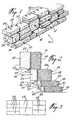
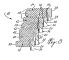
- a retaining wall 10 is shown made up of molded concrete blocks 12 of a predetermined thickness with blocks 14 being of a greater thickness and blocks 16 having still a further greater thickness.
- Each block 12, 14, or 16 has a front face 18, a rear face 20, a top surface 22, and a bottom surface 24.
- the block includes end surfaces 26.
- Each of the blocks 12, 14, 16 includes one or more keyhole-slots 30.
- Each keyhole-slot 30, as shown in Fig. 9 for instance, includes a circular cylindrical bore 32 and a neck portion 34.
- a retaining member 36 as shown in Fig. 6a, includes a stem portion 38 of circular cylindrical outline, and a shank portion 40 depending from the stem portion 38.
- the shank portion includes an extension of a segment of the cylindrical stem portion forming an abutment surface 41. This abutment surface is at right angle to the bottom surface 24 of the block when installed.
- the retaining member 36 fits into the keyhole-slot 30 and projects below the bottom surface 24 as shown.
- the shank member 40 including abutment surface 41 abuts against the rear surface of an adjacent lower block 12 or 14.
- the retaining member acts both as a spacer and a retainer for the laying of the molded blocks 12, 14, and 16, in constructing the retaining wall 10.
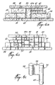
- the molded blocks 13, 15, and 17 have different thicknesses.
- three categories of thickness have been illustrated as exemplified by block 13 which measures 65 mm., block 15 which measures 86.7 mm. and block 17 has a thickness of 130 mm.
- the retaining wall should have a slope in order to retain the backfill behind the retaining wall. This is especially true when laying such molded blocks without mortar. In order that the retaining wall be topped off with a crown, the slope must be constant even though different thicknesses of blocks are being used. By aligning the corners at the intersections of the front face 18 and the top face 22, so that they are in the same sloped plane, the retaining wall will have a consistency such that the top surface of the retaining wall can be aligned longitudinally and in the same plane in order to receive a crown.
- the keyhole-slots 30 In order to achieve this alignment, it is necessary to configure the keyhole-slots 30 such that the keyhole-slots extend further inwardly of the block from the rear wall 20, then in a shallower block 12. For example, and as shown in Figs. 2 and 5, the extent of the keyhole-slots 30 measured from the rear face 20 is twice as great in molded block 14 as it is in molded block 12.
- the keyhole-slot 30 in molded block 16 has an inward dimension which is proportionally greater than that shown in molded blocks 14 or 12.
- the retaining members 36 are identical and are placed with a cylindrical portion snugly fitted into the bore 32 with a shank partly within the slotted neck portion 34, and projecting downwardly so that it will engage the rear face 20 of an adjacent block.
- Figs. 4a and 4b show an arrangement were one of the molded blocks 14 is placed in a vertical orientation as a jumper 14a.
- the jumper 14a should have a length in the X axis (the length is shown in the vertical orientation in the case of Figures 4a and 4b) such that the length is a multiple of the thickness of certain of the blocks used in the arrangement (along the Z axis). In certain cases where several thicknesses are utilized it would be sufficient for the length of the jumper block 14a to be equal to the sum of the thicknesses of the other blocks.
- a jumper 14a can be utilized, in the present embodiment, with a combination of two molded blocks 16 laid one on top of the other, or a combination of blocks 12 and 14.
- the jumper 14a may be useful in ensuring that the crown blocks 70 are in a common plane. Since jumper 14a is selected from a block 14, which would be supplied in the kit of blocks for building the retaining wall, it is obvious that the keyhole-slots 30 will no longer have a vertical orientation. Accordingly, in order to provide the proper slope or stagger for the retaining wall and the position of the jumper 14a in the retaining wall only the keyhole-slots in the lower portion of the jumper 14a, as shown in Fig. 4b, would be utilized while the other slots 30, in the upper portion of the jumper 14a, would remain empty. Thus retaining members 36 having abutment extensions 40 can extend from the lower portion of the jumper 14a to engage the rear surfaces of adjacent blocks, thereby staggering the jumper 14a from the bottom thereof so that it is properly aligned at the top portion of the blocks.
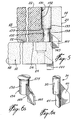
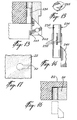
- Figs. 9 and 10 show a pair of blocks which are molded in one piece. Rear faces 20 of these blocks 12 are formed with keyhole-slots 30, each having a bore 32 and a slotted neck 34. In Fig. 9 different sizes of keyhole-slots 30 have been shown for purposes of illustration only. The blocks may have one or more keyhole-slots 30. The molded pair is fractured along fractionating groove 31 in order to form two blocks.
- the groove In order to properly fractionate the slab, the groove must form a V angle of less than 90 degrees. On the other hand a narrow groove leaves a less than attractive beveled surface on the block formed by fractionating the slab.
- a sub groove may be located within the groove to insure that the slab will always be split along the desired fractionating line.
- the groove 31 is provided with a sub groove 31a at the apex thereof.
- the groove 31 may have an angle of more than 90 degrees while the sub groove 31a will have an angle of less than 90 degrees. It has been found that the slab might merely be struck anywhere with a hammer blow and the fractionating line or split will occur consistently along the sub groove 31a.
- Fig. 6b shows another embodiment wherein the retaining member 130 is provided with a shoulder 137 formed on the cylindrical stem 138.
- the shank 140 includes a downward portion which is spaced from the tubular member 138 as shown at 143.
- the retaining member 138 is illustrated in Fig. 5 wherein the keyhole-slot has been altered to receive the particular retaining member 136.
- the keyhole-slot 130 includes a bore 132 and a frusto-conical shoulder 133 with the lower portion of the bore 132 being of smaller diameter.
- the retaining member 136 will sit in the bore 132 with the shoulder 137 sitting on the frusto-conical shoulder 133. This configuration insures that the retaining member is properly located in the keyhole-slot 130.
- Fig. 6c shows a further embodiment of the retaining member 36 which can be used in the keyhole-slots 30.
- the retaining member has a first circular cylindrical stem 38, a web 39, and a further circular cylindrical abutment member 40 which projects beyond the web. In installation it is this extension of the circular cylindrical abutment member 40 which will extend beyond the block.
- the retaining member 236 includes wings 235 which are slightly deformed when the cylindrical portion 238 is inserted in the corresponding bore 32 of the keyhole-slot 30, so as to reduce the chances of accidental displacement of the retaining member.
- Figs. 11 and 12 show two versions of the retaining member to which anchor ties can be accommodated.
- the retaining member 336 includes an opening 337 in the shank 340.
- the retaining member 436 includes a hook-shaped shank 440.
- Fig. 13 shows a still further embodiment of a retaining member adapted to be used with a molded block having a locking groove.
- the stem 536 includes a shank 540 with a short projection 549 adapted to engage the groove in the adjacent block.
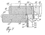
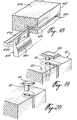
- Figs. 17 and 18 show a molded block to be used as a crown in which the keyhole-slot 50 extends only part-way through the block so that the top surface of the block 22 is uniform and uninterrupted.
- Fig. 18 shows a keyhole that extends longitudinally of the block 612.
- the keyhole-slot 630 is parallel to the top surface 622.
- the retaining member 636 shown in Fig. 18 has a cylindrical bead member 638, a web portion 639, and a shank 640 which is adapted to project below the bottom surface 624 of the molded block.
- Figs. 19 and 20 show different types of cap devices which could be used in the event a typical block 12, 14 or 16 is used as the capping member, so as to cover the keyhole-slot.
- the capping member includes a plug 56 with a cap portion 58 that is offset.
- Fig. 20 shows a similar device with a circular cap portion 60 and a stem portion 62.
- a retaining member 236, as shown in Fig. 14, is utilized with the stem 238 inserted into the bore 230 of block 12 from the top surface 222 thereof.
- the shank 240 extends upwardly from the top surface of the block.
- a crown 70 can then be set on the top of the retaining wall where the block 12 in Fig. 21 is in the uppermost row.
- Crown block 70 is provided with a longitudinal groove 72 as is conventional, and thus the shank 240 can protrude within the groove 72 in order to retain the crown block 70.
- the plug 62 with cap 60 can be utilized in relation to a crown block 70 to protrude within the groove 72, and thereby retain the crown block 70 against lateral movement.
- each block 12 would have a groove 72 on the bottom surface and a bore could be located in the block at a distance from the rear wall 20 proportional to the thickness of the block.
- the plug and cap 60 is then inserted into the bore and the cap extends into the groove, thereby locating and retaining the adjacent blocks.
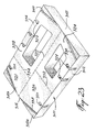
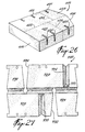
- a process for preparing a kit for building a retaining wall has also been contemplated wherein the process includes molding a slab of concrete 310 (Fig. 23).
- the slab 310 can be molded as a one-piece slab in a typical concrete block molding unit which might include a platform and removable side walls. It can also be molded by using intermediate mold plates in the mold to separate the mold modules. Thus the slab may consist of several blocks separated one from the other but molded in one mold cycle.
- the slab 310 has a rectangular outline in one embodiment measuring 610 mm. x 460 mm.
- the slab 310 has side walls 312 and 314 and end walls 316 and 318.
- the slab may be provided with through keyhole-slots 320 and blind keyhole-slots 321 along the longitudinal edges and extending inwardly from the side wall 312 and 314.
- the block module 328 would have through keyhole-slots 320 and blocks 324, 326 and 330 would have blind keyhole-slots 321.
- block modules 324, 326 can be used as capping members by inverting the blocks.
- a linear fractionating line 322 bisects the slab into two halves 310a and 310b.
- the fractionating line 322 extends parallel to the longitudinal axis X of the slab 310 from end wall 316 to end wall 318.
- each slab half portion measures 230 mm. in width.
- the line 322 is imaginary since in most cases the slab will be fractionated at the plant by suitable cutting tools.
- Each slab half 310a and 310b is then subdivided into concrete block modules 324, 326, 328 and 330.
- slab half 310a is subdivided into blocks 324 and 326 by means of fractionating line 332 while slab half 310b is separated into two block modules 328 and 330 by means of fractionating line 334.
- Fractionating lines 332 and 334 are parallel to transverse axis Y and extend from fractionating line 322 to the end walls 310 and 314 respectively. Fractionating lines 332 and 334 are at right angles to the fractionating lines 322.
- At least one surface of the slab in this case the top surface, could be provided with fractionating lines in the form of grooves 322, 332 and 334.
- the slab 310 could be molded with a mold plate along fractionating line 332 and once out of the mold, a fractionating blade could be used, at the factory, to separate the block modules along fractionating lines 332 and 334.
- block 324 now measures 360 mm. in length by 230 mm. in width.
- Block 326 measures 250 mm. x 230 mm.
- Block 328 measures 460 mm. x 230 mm.
- block 330 measures 150 mm. in length and 230 mm. in width.
- the keyholes 320 are located such that once the slab has been fractionated each resulting block 324, 326, 328 and 330 is provided with keyholes which will be useful in the case of using the retaining members.
- the block 324 in the present embodiment, may be provided with a fractionating groove 336 while block 326 is provided with a fractionating groove 338.
- Fractionating groove 336 extends from the end wall 318 to the side wall 312 at an obtuse angle to the axis X and in fact can be seen to form a right angle triangle between side walls 312, end wall 318, and the base of the triangle formed by a fractional groove 336.
- the block would not normally be separated at fractionating groove 336 unless it is required to form a curved radius in the retaining wall, in which case a number of blocks would be fractionated on site along a fractional line such as fractional groove 336, in order to provide an end face with an angle so that when merged with other blocks a radius or curve can be defined.
- the block modules 326 and 328 could be fractionated along lines 338 and 340 respectively, as part of the mold cycle. Thus blocks 326 and 328 would be predetermined on the pallet as blocks to form convex curves in the retaining wall.
- Slab 310 has a constant thickness, yet the kit may be made with blocks of different thicknesses. Accordingly a kit may be made up by blocks from selected slabs of different thicknesses.
- Fig. 24 shows another embodiment of a key-hole slot wherein the openings 520 in a typical block 12 have an accordion configuration while the stem 538 of retaining member 536 has a similar but shorter configuration so that the retaining member can be adjusted to adapt within the keyhole-slot 520.
- Figs. 25 and 26 show another embodiment of a slab, in this case identified 410.
- the block modules 424 and 428 are already preformed with angular end walls 436 and 440 respectively. These blocks 424 and 428 can be utilized to form a curve in the retaining wall or could be used as any block 12, 14 or 16.
- the keyhole-slots which pass through the thickness of the block module 430 and blind keyhole-slot 421 are shown with double bores. These double bore keyhole-slots permit the retaining member to be adjusted in terms of slope or stagger, either for a vertical wall or for a staggered wall.
- one of the block modules would preferably be selected such that the X axis dimension of that block module would be a multiple of the thickness of the block module. This enables any of the so formed block modules to be utilized as a jumper 14a.
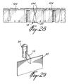
- FIG. 27 Another embodiment of the slab 710 is shown in Fig. 27.
- the blocks 724, 726, 728, and 730 have slots such as slots 732 and 734 instead of dividing lines.
- the slots 732 and 734 intersect the groove 733 which is parallel to the X axis and bisects the slab 710.
- Slabs 726 and 728 have further grooves 731 and 735 which can be fractured on site by the installer in order to provide a block with an end surface at right angles to the front or rear surfaces.
- the process further includes the step of preparing pallets on which the blocks are arranged in the pattern that should be utilized in building a retaining wall.
- assembling the retaining wall is rendered much easier, when the blocks have been predisposed on the shipping pallets.
- Many variations could be obtained from different predisposed arrangements on the pallets, including the provision of blocks of the same thickness, thus a slab could be fractionated and the block modules merely placed on a pallet.
- a retaining wall may be assembled by mixing blocks from any number of pallets.
- At least two of the block modules have a length relationship where one block is 10% longer than the other block. For instance, if block 426 has a dimension in the longitudinal axis which is A, then block 430 has a length dimension in the longitudinal axis which is A + A / 10.
- block 424 If block 424 is selected as the jumper, then the length L of block 424 must be a multiple the height T of the slab in the Z axis. In other words, block 424 must have an L dimension equal to 2T, 3T. . . . nT.
- At least one of the blocks such as blocks 426 or 430 has a right angle corner and a length l equal to a width w + L / 5.
- the width Y is constant for all of the blocks in the slab. At least one of the blocks in each slab must have an angle to the Y axis between 5° and 30°.
- Each block in a slab has accommodation for retaining members.
- Figs. 28 and 29 show a typical row of blocks 726 for instance. Since the end walls 734 may be at an angle a special retaining member 36 can be utilized as shown in Fig. 29.
- the retaining member 36 has a stem 38, a shank 39, and a flat abutment plate 40.
- the abutment plate 40 should be large enough to bridge the gap formed by the diverting end walls 734 of adjacent blocks 726.
- retaining member 36 shown in Fig. 28 extends downwardly from the row above.
Abstract
Description

Claims (11)
- A kit for a retaining wall (10) including at least two molded blocks (12) adapted to be placed in an overlying position one to the other, each block having top (22), bottom (24), front (18), rear (20), and end (26) faces wherein the top and bottom faces are parallel, an opening extending from one of the top, bottom or end faces, and perpendicular thereto, the opening being a keyhole slot (30, 520, 630) having a cylindrical bore or an accordion configurated bore and a neck portion opening to the rear face of the block, a retaining member (36, 136, 236, 536, 636) adapted to be inserted into the opening, the retaining member including a stem portion (38, 138, 238, 538, 638) to be fitted into the opening and a shank portion (40, 140, 240, 540, 640) projecting beyond one of the top, bottom and end faces with an abutment portion at right angle to the top and bottom faces, the abutment portion of the retaining member shank portion being adapted to engage a rear face of an adjacent block so as to retain one block in relation to the other.
- A kit for a retaining wall as defined in claim 1, wherein the bore (132) includes a lower portion of a predetermined diameter and an upper portion of increasing diameter forming a pilot hole, and the retaining member (136) includes a stem portion (138) having a diameter similar to the diameter of the lower portion and a flared cap (137) portion fitting within the upper portion of larger diameter, and the shank (140) is a flat planar member extending below the bottom wall (24) of the block (12) with the shank (140)inserted in the narrow neck (134) and offset from the axis of the stem (138) .
- A kit for a retaining wall as defined in claim 1, wherein the elongated keyhole slot (36) having a circular cylindrical component (32) in cross section and a narrow neck portion (34) extending to the rear face (20) of the block (12), and the retaining member (36) includes a circular cylindrical stem portion (38) which can fit in the circular cylindrical component (32) of the keyhole slot (30), and the shank (40) is a flat fin-like member offset from the stem (38) and aligned in a plane intersecting the axis of the circular cylindrical stem portion, the shank (40)also having an abutment portion (41) including an edge parallel to the axis of the circular cylindrical component (32) such that when the retaining member (36) is fitted within the keyhole slot (30)in the block (12), the shank portion (40)extends beyond the top (22) or bottom (24) face of the block (12), such that the abutment portion (41)is adapted to engage the rear face (20) of a vertically adjacent block (14) so as to provide an offset to the overlying block (14) and to provide the retaining wall (10) with a slope.
- A kit for a retaining wall as defined in claim 3, wherein the shank(40) includes an aperture(37) to be used to accommodate a tie means for an anchor.
- A kit for a retaining wall as defined in claim 3, in which each block has the form of a right prism with an X axis in the longitudinal direction and wherein the rear face (20) of a block is provided with a locking groove extending parallel to the X axis and the shank (540) of the retaining member (536) is provided at the abutment portion with a projection (549) to complement the locking groove, such that when the block overlies a vertically adjacent block the projection in the abutment portion(549) of the shank (541) engages the groove of the adjacent block.
- A kit for a retaining wall as defined in claim 3, wherein the stem portion (238) includes deformable wings(235) on the exterior surface thereof to provide a snug fit of the stem (238) within the bore (32).
- A kit for a retaining wall as defined in claim 3, wherein the keyhole slot(30) in the block (12) extends from the bottom wall (24) and is a blind opening such that the top face (22) is uninterrupted and the block (12) can be used as a capping member for the retaining wall (10).
- A kit for a retaining wall as defined in claim 3, wherein the keyhole slot (630) extends from one of the end faces (626) with en enlarged head portionand a narrow neckopening into the rear face (624) of the block (612), the retaining member (636) includes a stem portion (638) adapted to fit within the enlarged head of the keyhole opening, a web portions (639) extends from the stem (638) adapted to fit within the neck portion of the opening, and a flange (640) extends at right angles to the web (639), such that the flange (640) extends beyond one of the top (622) and bottom faces, and the flange (640) including an abutment portion adapted to engage the rear face of a vertically adjacent block.
- A kit for a retaining wall as defined in claim 5, wherein at least one of the blocks is a capping member (70) and has an elongated groove (72) in the bottom face thereof, the groove (72) extends between the end faces of the capping member (70) near the rear face thereof, and the capping member (70) being adapted to overly a vertically adjacent block (12), and the vertically adjacent block (12) includes an opening in the form of a keyhole slot (230) extending from the top face (222) of the block (12), and the retaining member (236) being fitted into the keyhole slot (230) from the top face (222) of the block (12) with the shank (240) projecting from the top face (222) thereof and adapted to engage the groove (72) in the capping member (70).
- A kit for a retaining wall as defined in claim 1, wherein the keyhole slot extends between the top (22) and bottom surfaces of the block (12), and a cap (58, 60) is provided which is insertable from the top surface (22) of the block (12) to cover the keyhole and therefore convert the block (12) into a capping member.
- A kit for a retaining wall as defined in claim 1, wherein the keyhole slot has an additional opening to form a double cylindrical bore keyhole-slot.
Applications Claiming Priority (3)
| Application Number | Priority Date | Filing Date | Title |
|---|---|---|---|
| CA002143379A CA2143379A1 (en) | 1995-02-24 | 1995-02-24 | Retaining wall system |
| CA2143379 | 1995-02-24 | ||
| PCT/CA1996/000057 WO1996026325A1 (en) | 1995-02-24 | 1996-01-30 | A retaining wall system |
Publications (2)
| Publication Number | Publication Date |
|---|---|
| EP0811095A1 EP0811095A1 (en) | 1997-12-10 |
| EP0811095B1 true EP0811095B1 (en) | 2003-06-04 |
Family
ID=4155307
Family Applications (1)
| Application Number | Title | Priority Date | Filing Date |
|---|---|---|---|
| EP96900804A Expired - Lifetime EP0811095B1 (en) | 1995-02-24 | 1996-01-30 | A retaining wall system |
Country Status (11)
| Country | Link |
|---|---|
| US (1) | US5735643A (en) |
| EP (1) | EP0811095B1 (en) |
| JP (1) | JPH11501374A (en) |
| AT (1) | ATE242367T1 (en) |
| AU (1) | AU4478596A (en) |
| CA (1) | CA2143379A1 (en) |
| DE (1) | DE69628546T2 (en) |
| DK (1) | DK0811095T3 (en) |
| ES (1) | ES2201168T3 (en) |
| NZ (1) | NZ300130A (en) |
| WO (1) | WO1996026325A1 (en) |
Families Citing this family (59)
| Publication number | Priority date | Publication date | Assignee | Title |
|---|---|---|---|---|
| US6449897B1 (en) | 1996-11-02 | 2002-09-17 | Johannes N. Gaston | Landscape edging system having adjustable blocks with recesses |
| US5865006A (en) * | 1997-06-02 | 1999-02-02 | Keystone Retaining Wall Systems, Inc. | Retaining wall block and wall construction |
| CA2214295C (en) * | 1997-08-29 | 2001-07-24 | Charles Ciccarello | Pre-cast rectangular cobblestone |
| AUPP647298A0 (en) * | 1998-10-13 | 1998-11-05 | Keystone Retaining Wall Systems, Inc. | Retaining wall block |
| US6115983A (en) * | 1999-01-14 | 2000-09-12 | E. P. Henry Corporation | Block assembly and wall constructed therefrom |
| US6149352A (en) * | 1999-02-11 | 2000-11-21 | Keystone Retaining Wall Systems, Inc. | Retaining wall block system |
| US6918715B2 (en) * | 1999-06-11 | 2005-07-19 | Anchor Wall Systems, Inc. | Block splitting assembly and method |
| US6488448B1 (en) * | 1999-10-15 | 2002-12-03 | Kiltie Corp. | Block module |
| US6543969B1 (en) * | 2000-08-10 | 2003-04-08 | Paul Adam | Modular block |
| US7096635B2 (en) * | 2001-03-02 | 2006-08-29 | Rockwood Retaining Walls, Inc. | Multiuse block and retaining wall |
| US6622445B1 (en) * | 2001-11-20 | 2003-09-23 | Ridgerock Retaining Walls, Inc. | Modular wall block with mechanical anchor pin |
| US7140867B2 (en) * | 2002-01-04 | 2006-11-28 | Anchor Wall Systems, Inc. | Mold for making a masonry block |
| US6862856B2 (en) | 2002-02-08 | 2005-03-08 | Anchor Wall Systems, Inc. | Corner block for use in forming a corner of a segmental retaining wall |
| US7788860B2 (en) * | 2003-07-07 | 2010-09-07 | Zartman Ronald R | Vandal proof system for securing a frangible facing plate to rigid supporting structure by wedging action and a method therefor |
| WO2005103393A1 (en) * | 2004-04-20 | 2005-11-03 | Toeishokou Kabushiki Kaisha | Block for retaining wall and step-like stacking method for the same |
| MXPA06012165A (en) * | 2004-04-29 | 2007-01-17 | Keystone Retaining Wall System | Veneers for walls, retaining walls and the like. |
| US6953309B1 (en) | 2004-07-13 | 2005-10-11 | Anchor Wall Systems, Inc. | Concrete block with batter indicators |
| US8176702B2 (en) * | 2004-11-22 | 2012-05-15 | Paul Adam | Modular block system |
| US7621095B2 (en) * | 2005-01-18 | 2009-11-24 | Dean Holding Corporation | Block-type retaining wall with planter feature |
| US20070110524A1 (en) * | 2005-11-15 | 2007-05-17 | Macdonald Robert A | Pin having a tapered cap |
| US20070258776A1 (en) * | 2006-04-24 | 2007-11-08 | Strand Todd P | Retaining wall systems |
| US8028688B2 (en) | 2006-10-18 | 2011-10-04 | Pavestone Company, Llc | Concrete block splitting and pitching apparatus and method |
| US7766002B2 (en) * | 2006-10-18 | 2010-08-03 | Pavestone Company, L.P. | Concrete block splitting and pitching apparatus |
| US9206599B2 (en) * | 2007-02-02 | 2015-12-08 | Les Materiaux De Construction Oldcastle Canada, Inc. | Wall with decorative facing |
| EP2118393A4 (en) * | 2007-02-02 | 2015-11-04 | Matériaux De Construction Oldcastle Canada Inc | Wall with decorative facing |
| USD585567S1 (en) | 2007-05-14 | 2009-01-27 | Anchor Wall Systems, Inc. | Molded surface of a concrete product |
| WO2008157828A2 (en) * | 2007-06-21 | 2008-12-24 | Keystone Retaining Wall Systems, Inc. | Veneers for walls, retaining walls, retaining wall blocks, and the like |
| US20090151281A1 (en) * | 2007-11-20 | 2009-06-18 | Keystone Retaining Wall Systems, Inc. | Method of constructing a wall or fence with panels |
| US20090148242A1 (en) * | 2007-12-10 | 2009-06-11 | Bruce Collet | Retaining wall system |
| US7849656B2 (en) * | 2008-04-18 | 2010-12-14 | Anchor Wall Systems, Inc. | Dry cast block arrangement and methods |
| USD619732S1 (en) | 2008-11-18 | 2010-07-13 | Anchor Wall Systems, Inc. | Molded surface of a concrete product |
| USD619733S1 (en) | 2008-11-18 | 2010-07-13 | Anchor Wall Systems, Inc. | Molded surfaces of a concrete product |
| USD619734S1 (en) | 2008-12-19 | 2010-07-13 | Anchor Wall Systems, Inc. | Molded surface of a concrete product |
| USD620133S1 (en) | 2009-02-25 | 2010-07-20 | Anchor Wall Systems, Inc. | Molded surface of a concrete product |
| CA2773448C (en) | 2009-09-29 | 2018-03-06 | Keystone Retaining Wall Systems, Inc. | Wall blocks, veneer panels for wall blocks and method of constructing walls |
| US9441342B2 (en) | 2010-09-28 | 2016-09-13 | Les Materiaux De Construction Oldcastle Canada, In | Retaining wall |
| MX345638B (en) | 2010-09-28 | 2017-02-08 | Les Matériaux De Construction Oldcastle Canada Inc | Retaining wall. |
| US9670640B2 (en) | 2010-09-28 | 2017-06-06 | Les Materiaux De Construction Oldcastle Canada, Inc. | Retaining wall |
| US10087597B2 (en) | 2010-12-21 | 2018-10-02 | Les Materiaux De Construction Oldcastle Canada, Inc. | Concrete wall block |
| CA2816643C (en) * | 2010-12-21 | 2015-12-01 | Les Materiaux De Construction Oldcastle Canada, Inc. | Concrete wall block |
| US9145676B2 (en) | 2011-11-09 | 2015-09-29 | E.P. Henry Corporation | Masonry block with taper |
| USD688813S1 (en) | 2012-04-19 | 2013-08-27 | Keystone Retaining Wall Systems Llc | Landscaping block |
| US20130276401A1 (en) | 2012-04-19 | 2013-10-24 | Keystone Retaining Wall Systems Llc | Wall block and wall block system |
| WO2014127486A1 (en) | 2013-02-25 | 2014-08-28 | Les Materiaux De Construction Oldcastle Canada Inc. | Wall assembly |
| US10583588B2 (en) | 2013-06-21 | 2020-03-10 | Pavestone, LLC | Manufactured retaining wall block with improved false joint |
| US20140373479A1 (en) | 2013-06-21 | 2014-12-25 | Pavestone, LLC | Adjustable locator retaining wall block and mold apparatus |
| USD791346S1 (en) | 2015-10-21 | 2017-07-04 | Pavestone, LLC | Interlocking paver |
| EP3007872B1 (en) | 2013-11-18 | 2019-01-09 | Pavestone LLC | Splitting apparatus for splitting a masonry block and method of processing such a block |
| US9725900B2 (en) * | 2014-01-08 | 2017-08-08 | Horacio Correia | Building blocks and rear interlock connector therefor |
| USD737468S1 (en) | 2014-05-07 | 2015-08-25 | Pavestone, LLC | Front face of a retaining wall block |
| WO2016134046A1 (en) | 2015-02-18 | 2016-08-25 | Keystone Retaining Wall Systems Llc | Blocks and block connectors, block systems and methods of making blocks |
| USD814278S1 (en) | 2016-07-21 | 2018-04-03 | Keystone Retaining Wall Systems Llc | Connector |
| USD812781S1 (en) | 2016-07-21 | 2018-03-13 | Keystone Retaining Wall Systems Llc | Wall block |
| US10156077B2 (en) | 2016-07-21 | 2018-12-18 | Keystone Retaining Wall Systems Llc | Veneer connectors, wall blocks, veneer panels for wall blocks, and walls |
| USD815938S1 (en) | 2016-07-21 | 2018-04-24 | Keystone Retaining Wall Systems Llc | Connector |
| USD814911S1 (en) | 2016-07-21 | 2018-04-10 | Keystone Retaining Wall Systems Llc | Connector |
| US10458092B1 (en) * | 2018-06-06 | 2019-10-29 | Horacio Correia | Modular retaining wall system and façade |
| BE1026597B1 (en) * | 2018-09-10 | 2020-04-09 | Gab Services Sprl | Construction element |
| CN109457725B (en) * | 2018-12-20 | 2023-10-24 | 西安航空学院 | H-shaped concrete plate assembled ecological retaining wall |
Family Cites Families (12)
| Publication number | Priority date | Publication date | Assignee | Title |
|---|---|---|---|---|
| GB420677A (en) * | 1933-06-02 | 1934-12-03 | Blockleys Ltd | Improvements in or relating to bricks |
| AT344574B (en) * | 1974-04-25 | 1978-07-25 | Ebenseer Betonwerke Gmbh | Process for the production of molded blocks |
| DE2731228C2 (en) * | 1977-07-11 | 1983-02-03 | Sf-Vollverbundstein-Kooperation Gmbh, 2820 Bremen | Concrete shaped stone for the production of a retaining wall and retaining wall made of such shaped stones |
| ATE97181T1 (en) * | 1988-09-30 | 1993-11-15 | Jean Louis Rossi | PLANTABLE RETAINING WALL WITH NICHES THAT CAN BE USED AS LOST FORMWORK. |
| US4920712A (en) * | 1989-01-31 | 1990-05-01 | Stonewall Landscape Systems, Inc. | Concrete retaining wall block, retaining wall and method of construction therefore |
| US4997316A (en) * | 1989-09-26 | 1991-03-05 | Rose George P | Method and apparatus for constructing a retaining wall |
| US4998397A (en) * | 1989-11-17 | 1991-03-12 | Orton Michael V | Alignment and lateral support member for use in laying common concrete blocks |
| US5044834A (en) * | 1990-07-26 | 1991-09-03 | Graystone Block Co., Inc. | Retaining wall construction and blocks therefor |
| DE4038489A1 (en) * | 1990-12-03 | 1992-06-04 | Metten Produktion & Handel | BUILDING BLOCKS FOR DRY WALLS |
| US5161918A (en) * | 1991-01-30 | 1992-11-10 | Wedgerock Corporation | Set-back retaining wall and concrete block and offset pin therefor |
| US5624211A (en) * | 1993-03-31 | 1997-04-29 | Societe Civile Des Brevets Henri C. Vidal | Modular block retaining wall construction and components |
| US5598679A (en) * | 1994-12-20 | 1997-02-04 | Orton; Michael V. | Cast concrete block and method of making same |
-
1995
- 1995-02-24 CA CA002143379A patent/CA2143379A1/en not_active Abandoned
-
1996
- 1996-01-22 US US08/589,640 patent/US5735643A/en not_active Expired - Lifetime
- 1996-01-30 JP JP8525255A patent/JPH11501374A/en not_active Ceased
- 1996-01-30 WO PCT/CA1996/000057 patent/WO1996026325A1/en active IP Right Grant
- 1996-01-30 EP EP96900804A patent/EP0811095B1/en not_active Expired - Lifetime
- 1996-01-30 DE DE69628546T patent/DE69628546T2/en not_active Expired - Lifetime
- 1996-01-30 AU AU44785/96A patent/AU4478596A/en not_active Abandoned
- 1996-01-30 ES ES96900804T patent/ES2201168T3/en not_active Expired - Lifetime
- 1996-01-30 DK DK96900804T patent/DK0811095T3/en active
- 1996-01-30 NZ NZ300130A patent/NZ300130A/en unknown
- 1996-01-30 AT AT96900804T patent/ATE242367T1/en active
Also Published As
| Publication number | Publication date |
|---|---|
| DK0811095T3 (en) | 2003-09-29 |
| WO1996026325A1 (en) | 1996-08-29 |
| DE69628546D1 (en) | 2003-07-10 |
| ES2201168T3 (en) | 2004-03-16 |
| CA2143379A1 (en) | 1996-08-25 |
| US5735643A (en) | 1998-04-07 |
| NZ300130A (en) | 1999-06-29 |
| DE69628546T2 (en) | 2004-04-29 |
| AU4478596A (en) | 1996-09-11 |
| EP0811095A1 (en) | 1997-12-10 |
| JPH11501374A (en) | 1999-02-02 |
| ATE242367T1 (en) | 2003-06-15 |
Similar Documents
| Publication | Publication Date | Title |
|---|---|---|
| EP0811095B1 (en) | A retaining wall system | |
| US6024517A (en) | Retaining wall system | |
| US6488448B1 (en) | Block module | |
| US4971475A (en) | Precast curb system | |
| US2392551A (en) | Interlocking building block | |
| US6474036B2 (en) | Retaining wall block | |
| US5154032A (en) | Building block system | |
| US7305803B2 (en) | Block construction system | |
| US5265396A (en) | Construction method of boardlike building elements | |
| US5537796A (en) | Retaining wall block and system | |
| US6233897B1 (en) | Landscaping block | |
| US20060150559A1 (en) | Two piece interlocking block system | |
| US6082933A (en) | Concrete block | |
| US4782640A (en) | Structural assembly for producing interconnected structures | |
| US20040040240A1 (en) | Insulated concrete wall system | |
| US20080277561A1 (en) | Mold box and method of manufacturing multiple blocks | |
| US5261760A (en) | Precast curb section | |
| US9453341B1 (en) | Wall system having core supporting blocks and decorative fascia blocks | |
| US4700527A (en) | Concrete masonry block wall cladding construction system and blocks for same | |
| EP0191104A1 (en) | Vertically assembling box type blocks | |
| AU716360B2 (en) | Kit for a retaining wall and a concrete slab for forming a block | |
| CA2213705C (en) | A retaining wall system | |
| US20050232696A1 (en) | System for supporting and leveling paving stones | |
| KR0132926Y1 (en) | Blocks | |
| JPH08209793A (en) | Variable-gradient gutter block |
Legal Events
| Date | Code | Title | Description |
|---|---|---|---|
| PUAI | Public reference made under article 153(3) epc to a published international application that has entered the european phase |
Free format text: ORIGINAL CODE: 0009012 |
|
| 17P | Request for examination filed |
Effective date: 19970915 |
|
| AK | Designated contracting states |
Kind code of ref document: A1 Designated state(s): AT BE CH DE DK ES FR GB GR IE IT LI LU MC NL PT SE |
|
| 17Q | First examination report despatched |
Effective date: 19981013 |
|
| RAP1 | Party data changed (applicant data changed or rights of an application transferred) |
Owner name: OLDCASTLE BUILDING PRODUCTS CANADA, INC. |
|
| GRAH | Despatch of communication of intention to grant a patent |
Free format text: ORIGINAL CODE: EPIDOS IGRA |
|
| GRAH | Despatch of communication of intention to grant a patent |
Free format text: ORIGINAL CODE: EPIDOS IGRA |
|
| GRAA | (expected) grant |
Free format text: ORIGINAL CODE: 0009210 |
|
| AK | Designated contracting states |
Designated state(s): AT BE CH DE DK ES FR GB GR IE IT LI LU MC NL PT SE |
|
| REG | Reference to a national code |
Ref country code: GB Ref legal event code: FG4D |
|
| REG | Reference to a national code |
Ref country code: CH Ref legal event code: EP |
|
| REG | Reference to a national code |
Ref country code: IE Ref legal event code: FG4D |
|
| REF | Corresponds to: |
Ref document number: 69628546 Country of ref document: DE Date of ref document: 20030710 Kind code of ref document: P |
|
| PG25 | Lapsed in a contracting state [announced via postgrant information from national office to epo] |
Ref country code: PT Free format text: LAPSE BECAUSE OF FAILURE TO SUBMIT A TRANSLATION OF THE DESCRIPTION OR TO PAY THE FEE WITHIN THE PRESCRIBED TIME-LIMIT Effective date: 20030904 Ref country code: GR Free format text: LAPSE BECAUSE OF FAILURE TO SUBMIT A TRANSLATION OF THE DESCRIPTION OR TO PAY THE FEE WITHIN THE PRESCRIBED TIME-LIMIT Effective date: 20030904 |
|
| REG | Reference to a national code |
Ref country code: SE Ref legal event code: TRGR |
|
| REG | Reference to a national code |
Ref country code: DK Ref legal event code: T3 |
|
| REG | Reference to a national code |
Ref country code: CH Ref legal event code: NV Representative=s name: MICHELI & CIE INGENIEURS-CONSEILS |
|
| PGFP | Annual fee paid to national office [announced via postgrant information from national office to epo] |
Ref country code: MC Payment date: 20040130 Year of fee payment: 9 |
|
| PGFP | Annual fee paid to national office [announced via postgrant information from national office to epo] |
Ref country code: LU Payment date: 20040203 Year of fee payment: 9 |
|
| REG | Reference to a national code |
Ref country code: ES Ref legal event code: FG2A Ref document number: 2201168 Country of ref document: ES Kind code of ref document: T3 |
|
| PLBE | No opposition filed within time limit |
Free format text: ORIGINAL CODE: 0009261 |
|
| STAA | Information on the status of an ep patent application or granted ep patent |
Free format text: STATUS: NO OPPOSITION FILED WITHIN TIME LIMIT |
|
| ET | Fr: translation filed | ||
| 26N | No opposition filed |
Effective date: 20040305 |
|
| PG25 | Lapsed in a contracting state [announced via postgrant information from national office to epo] |
Ref country code: LU Free format text: LAPSE BECAUSE OF NON-PAYMENT OF DUE FEES Effective date: 20050130 |
|
| PG25 | Lapsed in a contracting state [announced via postgrant information from national office to epo] |
Ref country code: MC Free format text: LAPSE BECAUSE OF NON-PAYMENT OF DUE FEES Effective date: 20050131 |
|
| PGFP | Annual fee paid to national office [announced via postgrant information from national office to epo] |
Ref country code: IT Payment date: 20111223 Year of fee payment: 17 |
|
| PGFP | Annual fee paid to national office [announced via postgrant information from national office to epo] |
Ref country code: DK Payment date: 20121220 Year of fee payment: 18 |
|
| PGFP | Annual fee paid to national office [announced via postgrant information from national office to epo] |
Ref country code: SE Payment date: 20121227 Year of fee payment: 18 |
|
| PGFP | Annual fee paid to national office [announced via postgrant information from national office to epo] |
Ref country code: ES Payment date: 20130109 Year of fee payment: 18 Ref country code: FR Payment date: 20130305 Year of fee payment: 18 |
|
| PGFP | Annual fee paid to national office [announced via postgrant information from national office to epo] |
Ref country code: NL Payment date: 20121220 Year of fee payment: 18 |
|
| PGFP | Annual fee paid to national office [announced via postgrant information from national office to epo] |
Ref country code: AT Payment date: 20121221 Year of fee payment: 18 |
|
| PGFP | Annual fee paid to national office [announced via postgrant information from national office to epo] |
Ref country code: DE Payment date: 20140122 Year of fee payment: 19 Ref country code: BE Payment date: 20140122 Year of fee payment: 19 Ref country code: CH Payment date: 20140123 Year of fee payment: 19 Ref country code: IE Payment date: 20140122 Year of fee payment: 19 |
|
| PGFP | Annual fee paid to national office [announced via postgrant information from national office to epo] |
Ref country code: GB Payment date: 20140127 Year of fee payment: 19 |
|
| REG | Reference to a national code |
Ref country code: NL Ref legal event code: V1 Effective date: 20140801 |
|
| REG | Reference to a national code |
Ref country code: DK Ref legal event code: EBP Effective date: 20140131 |
|
| REG | Reference to a national code |
Ref country code: AT Ref legal event code: MM01 Ref document number: 242367 Country of ref document: AT Kind code of ref document: T Effective date: 20140130 |
|
| REG | Reference to a national code |
Ref country code: SE Ref legal event code: EUG |
|
| PG25 | Lapsed in a contracting state [announced via postgrant information from national office to epo] |
Ref country code: NL Free format text: LAPSE BECAUSE OF NON-PAYMENT OF DUE FEES Effective date: 20140801 |
|
| REG | Reference to a national code |
Ref country code: FR Ref legal event code: ST Effective date: 20140930 |
|
| PG25 | Lapsed in a contracting state [announced via postgrant information from national office to epo] |
Ref country code: AT Free format text: LAPSE BECAUSE OF NON-PAYMENT OF DUE FEES Effective date: 20140130 Ref country code: FR Free format text: LAPSE BECAUSE OF NON-PAYMENT OF DUE FEES Effective date: 20140131 Ref country code: SE Free format text: LAPSE BECAUSE OF NON-PAYMENT OF DUE FEES Effective date: 20140131 |
|
| PG25 | Lapsed in a contracting state [announced via postgrant information from national office to epo] |
Ref country code: DK Free format text: LAPSE BECAUSE OF NON-PAYMENT OF DUE FEES Effective date: 20140131 |
|
| REG | Reference to a national code |
Ref country code: ES Ref legal event code: FD2A Effective date: 20150330 |
|
| PG25 | Lapsed in a contracting state [announced via postgrant information from national office to epo] |
Ref country code: ES Free format text: LAPSE BECAUSE OF NON-PAYMENT OF DUE FEES Effective date: 20140131 |
|
| PG25 | Lapsed in a contracting state [announced via postgrant information from national office to epo] |
Ref country code: BE Free format text: LAPSE BECAUSE OF NON-PAYMENT OF DUE FEES Effective date: 20150131 |
|
| REG | Reference to a national code |
Ref country code: DE Ref legal event code: R119 Ref document number: 69628546 Country of ref document: DE |
|
| REG | Reference to a national code |
Ref country code: CH Ref legal event code: PL |
|
| GBPC | Gb: european patent ceased through non-payment of renewal fee |
Effective date: 20150130 |
|
| PG25 | Lapsed in a contracting state [announced via postgrant information from national office to epo] |
Ref country code: GB Free format text: LAPSE BECAUSE OF NON-PAYMENT OF DUE FEES Effective date: 20150130 Ref country code: CH Free format text: LAPSE BECAUSE OF NON-PAYMENT OF DUE FEES Effective date: 20150131 Ref country code: DE Free format text: LAPSE BECAUSE OF NON-PAYMENT OF DUE FEES Effective date: 20150801 Ref country code: LI Free format text: LAPSE BECAUSE OF NON-PAYMENT OF DUE FEES Effective date: 20150131 |
|
| REG | Reference to a national code |
Ref country code: IE Ref legal event code: MM4A |
|
| PG25 | Lapsed in a contracting state [announced via postgrant information from national office to epo] |
Ref country code: IE Free format text: LAPSE BECAUSE OF NON-PAYMENT OF DUE FEES Effective date: 20150130 |
|
| PG25 | Lapsed in a contracting state [announced via postgrant information from national office to epo] |
Ref country code: IT Free format text: LAPSE BECAUSE OF NON-PAYMENT OF DUE FEES Effective date: 20140130 |