EP0810946B1 - Dispositif de pressurisation d'un sous-systeme de propulsion biliquide unifie d'un satellite geostationnaire - Google Patents
Dispositif de pressurisation d'un sous-systeme de propulsion biliquide unifie d'un satellite geostationnaire Download PDFInfo
- Publication number
- EP0810946B1 EP0810946B1 EP96904890A EP96904890A EP0810946B1 EP 0810946 B1 EP0810946 B1 EP 0810946B1 EP 96904890 A EP96904890 A EP 96904890A EP 96904890 A EP96904890 A EP 96904890A EP 0810946 B1 EP0810946 B1 EP 0810946B1
- Authority
- EP
- European Patent Office
- Prior art keywords
- tanks
- valve
- pressure
- pyrotechnic
- satellite
- Prior art date
- Legal status (The legal status is an assumption and is not a legal conclusion. Google has not performed a legal analysis and makes no representation as to the accuracy of the status listed.)
- Expired - Lifetime
Links
- 239000007788 liquid Substances 0.000 title claims description 14
- 239000003380 propellant Substances 0.000 claims description 56
- SWQJXJOGLNCZEY-UHFFFAOYSA-N helium atom Chemical compound [He] SWQJXJOGLNCZEY-UHFFFAOYSA-N 0.000 claims description 29
- 239000001307 helium Substances 0.000 claims description 27
- 229910052734 helium Inorganic materials 0.000 claims description 27
- 239000002828 fuel tank Substances 0.000 claims description 15
- 238000005259 measurement Methods 0.000 claims description 14
- 238000012546 transfer Methods 0.000 claims description 14
- 230000001105 regulatory effect Effects 0.000 claims description 11
- 238000012545 processing Methods 0.000 claims description 10
- 239000007800 oxidant agent Substances 0.000 claims description 9
- 238000012360 testing method Methods 0.000 claims description 8
- 239000007789 gas Substances 0.000 description 17
- 238000002955 isolation Methods 0.000 description 12
- 230000001590 oxidative effect Effects 0.000 description 6
- 238000004891 communication Methods 0.000 description 5
- 206010011906 Death Diseases 0.000 description 4
- 238000000034 method Methods 0.000 description 4
- 238000009529 body temperature measurement Methods 0.000 description 3
- 239000000446 fuel Substances 0.000 description 3
- 238000012423 maintenance Methods 0.000 description 3
- 238000009530 blood pressure measurement Methods 0.000 description 2
- 230000005484 gravity Effects 0.000 description 2
- HDZGCSFEDULWCS-UHFFFAOYSA-N monomethylhydrazine Chemical compound CNN HDZGCSFEDULWCS-UHFFFAOYSA-N 0.000 description 2
- 230000037452 priming Effects 0.000 description 2
- 238000010926 purge Methods 0.000 description 2
- 238000000926 separation method Methods 0.000 description 2
- 238000011144 upstream manufacturing Methods 0.000 description 2
- 238000013022 venting Methods 0.000 description 2
- 235000015842 Hesperis Nutrition 0.000 description 1
- 235000012633 Iberis amara Nutrition 0.000 description 1
- 230000003247 decreasing effect Effects 0.000 description 1
- OMBRFUXPXNIUCZ-UHFFFAOYSA-N dioxidonitrogen(1+) Chemical compound O=[N+]=O OMBRFUXPXNIUCZ-UHFFFAOYSA-N 0.000 description 1
- 230000000694 effects Effects 0.000 description 1
- 235000021183 entrée Nutrition 0.000 description 1
- 238000004880 explosion Methods 0.000 description 1
- 239000002360 explosive Substances 0.000 description 1
- -1 for example two Substances 0.000 description 1
- 238000009413 insulation Methods 0.000 description 1
- 238000000691 measurement method Methods 0.000 description 1
- 238000012986 modification Methods 0.000 description 1
- 230000004048 modification Effects 0.000 description 1
- 230000005855 radiation Effects 0.000 description 1
- 238000007789 sealing Methods 0.000 description 1
Images


Classifications
-
- G—PHYSICS
- G01—MEASURING; TESTING
- G01F—MEASURING VOLUME, VOLUME FLOW, MASS FLOW OR LIQUID LEVEL; METERING BY VOLUME
- G01F22/00—Methods or apparatus for measuring volume of fluids or fluent solid material, not otherwise provided for
- G01F22/02—Methods or apparatus for measuring volume of fluids or fluent solid material, not otherwise provided for involving measurement of pressure
-
- B—PERFORMING OPERATIONS; TRANSPORTING
- B64—AIRCRAFT; AVIATION; COSMONAUTICS
- B64G—COSMONAUTICS; VEHICLES OR EQUIPMENT THEREFOR
- B64G1/00—Cosmonautic vehicles
- B64G1/22—Parts of, or equipment specially adapted for fitting in or to, cosmonautic vehicles
- B64G1/40—Arrangements or adaptations of propulsion systems
- B64G1/402—Propellant tanks; Feeding propellants
-
- G—PHYSICS
- G01—MEASURING; TESTING
- G01F—MEASURING VOLUME, VOLUME FLOW, MASS FLOW OR LIQUID LEVEL; METERING BY VOLUME
- G01F23/00—Indicating or measuring liquid level or level of fluent solid material, e.g. indicating in terms of volume or indicating by means of an alarm
- G01F23/14—Indicating or measuring liquid level or level of fluent solid material, e.g. indicating in terms of volume or indicating by means of an alarm by measurement of pressure
-
- B—PERFORMING OPERATIONS; TRANSPORTING
- B64—AIRCRAFT; AVIATION; COSMONAUTICS
- B64G—COSMONAUTICS; VEHICLES OR EQUIPMENT THEREFOR
- B64G1/00—Cosmonautic vehicles
- B64G1/22—Parts of, or equipment specially adapted for fitting in or to, cosmonautic vehicles
- B64G1/24—Guiding or controlling apparatus, e.g. for attitude control
- B64G1/242—Orbits and trajectories
- B64G1/2427—Transfer orbits
-
- B—PERFORMING OPERATIONS; TRANSPORTING
- B64—AIRCRAFT; AVIATION; COSMONAUTICS
- B64G—COSMONAUTICS; VEHICLES OR EQUIPMENT THEREFOR
- B64G1/00—Cosmonautic vehicles
- B64G1/22—Parts of, or equipment specially adapted for fitting in or to, cosmonautic vehicles
- B64G1/24—Guiding or controlling apparatus, e.g. for attitude control
- B64G1/26—Guiding or controlling apparatus, e.g. for attitude control using jets
Definitions
- the present invention relates to a pressurization device of a unified biliquid propulsion subsystem of a geostationary satellite.
- Telecommunication satellites are placed in an orbit in the plane of the Earth's equator about 36,000 km from Earth.
- This orbit circular has the particularity that any object orbited on this orbit has a twenty four hour rotation period around the earth. So an object orbit appears motionless above the earth for a terrestrial observer.
- This privileged orbit allows telecommunication satellites to fill at least better their relay function of communication between several points located on Earth.
- the biliquid engine is supplied from the same tanks and primary circuits as the other propellers necessary for attitude and orbit control.
- helium approximately 18 bars
- two propellants are used, for example, monomethylhydrazine (MMH) as the fuel and nitrogen peroxide (N 2 O 4 ) as the oxidant.
- the most common cause that causes the end of life of the satellite is the consumption of all the propellants allowing the maintenance at satellite station and its pointing to the earth.
- the satellite Once stationed in its orbital position, the satellite is subject to disturbing forces (lunisolar attraction, radiation pressure solar, etc.) which tend to make it describe cyclical movements of increasing amplitude around the initial position.
- the ground stations being pointed at a fixed point in the sky, in order to avoid over-equipment of ground stations with satellite tracking devices, and to maintain the satellite on the allocated orbital position, it is necessary to intervene periodically to to oppose the disturbing movements of the satellite, by periodically burning a quantity of propellants in the orbit control engines.
- the satellite is also subject to disruptive torques around its center of gravity which would lead to depoin him. A quantity of propellants is therefore also periodically burned in attitude control engines.
- the user requests to know the date of obsolescence of the satellite far enough in advance to launch the activities necessary to its replacement.
- the satellite operator must therefore be able to predict with certainty the end of the consumption of propellants, so as to trigger the operation orbit. If the knowledge system is not precise, we lose all the more time to use and market the satellite as it medium is imprecise.
- the propellant tank is repressurized by a brief opening of the interconnection valve between the relatively higher pressure pressure tank and the tank propellants.
- the interconnection valve is closed before pressure equalization between the two tanks to allow multiple measurements to be made at during the satellite mission.
- Pressure and temperature measurements tanks before and after repressurization make it possible to determine the volume of residual gas in the propellant tank by calculation according to the gas law. Knowledge of this volume and that of the total volume of the reservoirs of propellants we deduce the volume of liquid present and, by that, the mass of propellants available.
- a German patent application DE-8 806 777 describes a device for weightlessness measurement of the quantity of liquid, in particular of the quantity of propellants, contained in the satellite tanks, in which a propellant tank is connected to a compressed gas tank via a pressurized gas supply line, in which is installed a measuring device giving the quantity of gas transferred during the setting up device artwork.
- An isolation (or interconnection) valve allows maintain a pressure in the tank containing the compressed gas greater than that of the propellant tank.
- a pressure sensor makes it possible to determine also the pressure of the gas contained in the propellant tank.
- French patent application N ° 91 15441 dated December 12 1991 describes a device for periodically measuring the residual volume of liquid in a closed pressure tank containing a liquid, which is gradually withdrawn, and a sparingly soluble gas therein, which includes a source of pressurized gas, a regulator-regulator supplying the reservoir and constructed so as to permanently prevent pressure in the tank to drop below a predetermined P value, means allowing gas to be admitted under a pressure P + ⁇ P into the tank at through a throttle and means for measuring the duration of passage of the internal pressure from P to P + ⁇ P.
- the measurement of the residual propellants during the phase of orbital life is achieved by independent valve devices mounted in parallel to the main regulated pressurization line.
- the pressurization of the satellite biliquid propulsion subsystem and the measurement of the quantity of residual propellants take place during this orbital life phase by a method of repressurization (or "re-inflation").
- the object of the invention is not in the measurement method used, which is that described in French patent application FR-A-2 629 913 (Glash) and in the article entitled “Low-Gravity Propellant Gauging System for Accurate Predictions of Spacecraft End-of-Life ", previously analyzed.
- the object of the invention is to ensure, by a single and same sub-assembly (redundant) of calibrated valves and orifices, the two functions of regulated pressurization during the transfer and stationing phase of the satellite, and "re-inflation" during the orbital life phase.
- helium storage tanks communicate with the fuel tank and the oxidant tank by several lines.
- a first pipe is inserted a first pyrotechnic valve, a first filter, a second and a third valve pyrotechnics in parallel, each one arranged in series with one element calibrated leak.
- a second and a third pipes are inserted a non-return valve, a fourth or sixth pyrotechnic valve and a fifth or seventh pyrotechnic valve separated by a second or third filter.
- the helium storage circuit is completed by a filling and emptying on the ground, by a test socket and by a system of pressure.
- the pressurization system is completed by test and by pressure sensors.
- the solenoid valves are arranged respectively between the second (and the third) valve pyrotechnic and the corresponding calibrated leak element between the second filter and the fifth pyrotechnic valve and between the third filter and the seventh valve pyrotechnic
- the processing and control circuit receives information from pressure sensors associated with helium tanks and sensors pressure associated with propellant tanks.
- the device of the invention has at least two fuel tanks and at least two tanks oxidant, the elements of the second and third lines associated with first tanks then being duplicated; pyrotechnic valves and branch elements, illustrated in FIG. 4 with "'" thus being relative to a propellant subsystem configuration with more than two tanks propellants.
- the device of the invention in its pressurization function constant, can be likened to an electronic type regulator. He introduces in particular the advantage of allowing adjustment or modification in flight only regulated pressure, which is impossible with a regulator mechanical.
- the solenoid valves ensure the insulation of the high pressure helium part of the propellant tanks with a rate sealing required.
- the measurement of the residual propellants in each tank can take place at regular intervals during orbital life. It consists, by a opening / closing of solenoid valves, to reintroduce helium in the propellant tanks.
- Knowledge of pressure variations provided by sensors then allows to know the free volume and therefore that of liquid present in fuel tanks.
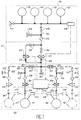
- Helium storage tanks 13, 14, 15 and 16 (here four in parallel) communicate with the fuel tank 17 and the tank oxidant 18 via lines 20, 21 and 22.
- first valve pyrotechnic 23 In the first pipe 20 is inserted a first valve pyrotechnic 23, a first filter 24, a second and a third valve pyrotechnics 25 and 26 in parallel, each one arranged in series with a leak element calibrated 27 and 28.
- each of the second and third lines 21 and 22 are inserted a non-return valve 30 and 31, a fourth pyrotechnic valve and a fifth pyrotechnic valve 32 and 36 separated by a second filter 38 (or a sixth and a seventh pyrotechnic valves 33 and 37 separated by a third filter 39).
- the helium 10 storage circuit is completed by a valve filling and emptying on the ground 41, by a test socket 42, and by a pressure sensor 43.
- the pressurization assembly 12 is completed by intakes of test 45, 46 and 55 and by pressure sensors 47 and 48.
- solenoid valves 50, 51, 52 are introduced. and 53 controlled by a processing and control circuit 54, in different places of this circuit; respectively between the second 25 (and the third 26) pyrotechnic valve and the corresponding calibrated leak element 27 or 28, between the second filter 38 and the fifth pyrotechnic valve 36 and between the third filter 39 and the seventh pyrotechnic valve 37.
- the treatment and control 54 receives information from pressure sensors 43 associated with helium tanks 13, 14, 15 and 16 and pressure sensors 47 and 48 associated with the propellant tanks 17 and 18.
- valve 50 is here to provide redundancy only and is not essential to the operation of the device.
- solenoid valves 52 and 53 can operate independently and thus allow an individual and independent measurement of the quantities of liquid present in the tanks.
- the filling valve 41 makes it possible to fill the tanks helium 13, 14, 15 and 16 on the ground, at 300 bars, the first pyrotechnic valve 23 being normally closed, the rest of the circuit remaining at low pressure. This valve is open after separation of the satellite from the launcher.
- Non-return valves 30 and 31 prevent mixing of the two propellants which would be explosive.
- Filters 24, 38 and 39 located at the outlet of the valves protect the downstream circuits.
- the fifth and seventh pyrotechnic valves 36 and 37 normally remain open until the end of the satellite's life. They are not used only in the event of a leak and risk of explosion, their ignition allowing to isolate the propellant tanks 17, 18 with respect to the helium tanks 13, 14, 15 and 16.
- pyrotechnic valves their number and location are primarily dictated by considerations of security and compliance with the ground safeguard requirements of the range authorities.
- the processing and control circuit 54 sends orders opening / closing to the solenoid valves located in the pressurization of propellant tanks. So during the transfer phase and satellite set-up, after configuration of the subsystem, the pressurization and the maintenance thereof is carried out by means of solenoid valves whose opening / closing orders are generated by the circuit of processing and ordering on comparison of data provided by pressure sensors with only desired regulation presets, these only can possibly be modified remotely.
- the curves giving the pressure of PE propellants as a function of time t illustrate the evolution of the frequency of control of the regulation solenoid valve 51 as a function of time during the transfer phase and peak maneuvers the volume of gas in the propellant tanks being 100 liters in the case of Figure 2 and 400 liters in the case of Figure 3; this operating example being considered for regulatory thresholds set at 17.9 and 18.1 respectively.
- the device of the invention therefore comprises two phases of operation:
- a failure of the nominal channel causes the closure of the pyrotechnic valve (29) and the opening (not necessarily simultaneous) of the track redundant (25).
- the solenoid valves insulate the high helium part pressure (in which there are only about 60 bars left after setting up) propellant tanks with the required tightness rate. Measuring propellants residual in each tank can be done at regular intervals during orbital life. It consists of opening / closing the solenoid valves to reintroduce helium in the propellant tanks. Knowledge of pressure variations provided by the sensors then allows to know the free volume and therefore that of liquid present in the propellant tanks.
- Valve failure or leakage causes the valves to close pyrotechnics which then completely isolates the helium circuit and we are brought back to the configuration that exists today on all subsystems that evolve in so-called "blow-down" mode during orbital life.
- Helium pressure upstream of the first valve Normally closed pyrotechnic 23 is equal to 300 bars.
- the circuit downstream of this valve and up to the isolation valves 70, 71, 72 and 73 which are in the closed position is under pressure of about 4 bars helium.
- the tanks are filled with propellants to 98% of their capacity (for ground safety reasons in case of temperature rise).
- the rest of the circuit is also pressurized under 4 bars helium.
- the isolation valves 74 and 75 which allow the flight to be selected functional branch or its redundant are closed.
- the system is then operational and we can therefore use the propellants.
- This phase requires, for engine operation liquid apogee 60 during apogee maneuvers, that the pressure is regulated in the tanks. When there is flow, this regulation is ensured by the solenoid valve 51 (or the solenoid valve 50) on orders prepared by the electronics of processing and ordering 54.
- solenoid valve 51 and the solenoid valve 52 ' for example, it is possible to reintroduce, at intervals regular during orbital life, helium in the 17 'reservoir.
- the measurement of pressure variations by the sensors 43 and 47 'then makes it possible to know the amount of liquid in this tank.
Landscapes
- Engineering & Computer Science (AREA)
- Physics & Mathematics (AREA)
- Fluid Mechanics (AREA)
- General Physics & Mathematics (AREA)
- Chemical & Material Sciences (AREA)
- Combustion & Propulsion (AREA)
- Remote Sensing (AREA)
- Aviation & Aerospace Engineering (AREA)
- Filling Or Discharging Of Gas Storage Vessels (AREA)
- Measuring Fluid Pressure (AREA)
Description
- une conduite reliant directement la sortie du réservoir de gaz de pressurisation et l'entrée du réservoir de carburant, cette conduite contenant un venturi;
- une première vanne répondant à un signal de commande pour laisser s'introduire le gaz de pressurisation dans la conduite au début de la mission spatiale ;
- une deuxième vanne répondant à un signal de commande pour fermer la communication entre la conduite et le réservoir de carburant à un moment prédéterminé au cours de la mission spatiale;
- un premier transducteur de pression connecté pour mesurer la pression P1, ΔP1 en amont de la première vanne ; et
- un deuxième transducteur de pression pour mesurer la pression P2, ΔP2 en aval de la deuxième vanne.
- un ensemble de stockage d'hélium haute pression comportant au moins un réservoir d'hélium ;
- un ensemble de régulation ;
- un ensemble de pressurisation de réservoirs d'ergols, reliés
entre eux par un circuit de pressurisation;
caractérisé en ce que l'ensemble de régulation est un ensemble de régulation électronique comprenant plusieurs électrovannes, disposées en différents endroits du circuit de pressurisation, ces électrovannes étant commandées par un circuit de traitement et de commande qui reçoit des informations issues de capteurs de pression associés aux différents réservoirs, ce circuit de commande permettant une pressurisation à pression constante des réservoirs d'ergols pendant la phase de transfert et de mise à poste du satellite, et une mesure de la quantité d'ergols résiduels pendant la phase de vie orbitale du satellite.
- La figure 1 illustre schématiquement le dispositif de l'invention;
- les figures 2 et 3 représentent des courbes illustrant l'évolution de pression dans les réservoirs d'ergols en fonction du temps;
- la figure 4 est relative à la partie liquide du sous-système propulsif située en aval du dispositif objet de l'invention, lui-même situé dans la partie gazeuse de pressurisation.
- un ensemble 10 de stockage d'hélium haute pression comprenant notamment des réservoirs de stockage d'hélium 13, 14, 15 et 16 ;
- un ensemble 11 de régulation électronique ;
- un ensemble 12 de pressurisation comprenant notamment deux réservoirs d'ergols à savoir un réservoir de combustible 17 et un réservoir d'oxydant 18.
- une fonction de pressurisation à pression constante des réservoirs d'ergols pendant la phase de transfert et de mise à poste du satellite ;
- une fonction de repressurisation ou de "regonflage" des réservoirs d'ergols permettant une mesure de la quantité d'ergols résiduels durant la phase de vie orbitale.
- des vannes pyrotechniques 65, 66, 67 et 68;
- des vannes d'isolation 70, 71, 72, 73, 74 et 75;
- des vannes de remplissage 76, 77, 78 et 79;
- des prises de test 80, 81, 82, 83;
- des filtres 84, 85, 86, 87, 88 et 89;
- des éléments de fuite calibrée 90, 91, 92, 93, 94 et 95 ;
- des capteurs de pression 96, 97, 98 et 99.
- purge des lignes ou conduitres ("venting")
- ouverture des vannes pyrotechniques 36 et 37,
- ouverture des vannes d'isolation 74 et 75,
- ouverture des vannes du moteur d'apogée 60 et d'un ou deux propulseurs d'attitude pendant environ 30 secondes.
- remplissage des lignes en ergols ("priming")
- ouverture des vannes d'isolation 72 et 73 (un seul réservoir
de chaque ergol),
la pression des lignes doit s'établir à 4 bars environ (pression initiale réservoirs) ;
- ouverture des vannes d'isolation 72 et 73 (un seul réservoir
de chaque ergol),
- pressurisation du sous-système
- ouverture des vannes d'isolation 70 et 71,
- ouverture des vannes pyrotechniques 32, 32', 33 et 33' (ces vannes servent à isoler les ergols l'un de l'autre jusqu'à cet instant. Ensuite ce sont les électrovannes 52, 52', 53 et 53' et les clapets anti-retour 30 et 31 qui assureront cette fonction).
- ouverture des vannes 52, 52', 53 et 53',
- ouverture de la vanne pyrotechnique 23.
Claims (9)
- Dispositif de pressurisation d'un sous-système de propulsion biliquide unifié d'un satellite géostationnaire, comprenant :un ensemble (10) de stockage d'hélium haute pression comportant au moins un réservoir de stockage d'hélium;un ensemble (11) de régulation;un ensemble (12) de pressurisation de réservoirs d'ergols (17, 18), reliés entre eux par un circuit de pressurisation ;
caractérisé en ce que l'ensemble de régulation est un ensemble de régulation électronique comprenant au moins une électrovanne (51), disposée en un endroit du circuit de pressurisation, et commandée par un circuit de traitement et de commande (54) qui reçoit des informations issues de capteurs de pression (43, 47, 48) associés aux différents réservoirs, ce circuit de traitement et de commande permettant une pressurisation à pression constante des réservoirs d'ergols (17, 18) pendant la phase de transfert et de mise à poste du satellite, et une mesure de la quantité d'ergols résiduels pendant la phase de vie orbitale du satellite. - Dispositif selon la revendication 1, caractérisé en ce qu'il comporte au moins un réservoir de combustible (17) et un réservoir d'oxydant (18).
- Dispositif selon la revendication 2, caractérisé en ce que les réservoirs de stockage d'hélium communiquent avec le réservoir de combustible (17) et le réservoir d'oxydant (18) par plusieurs conduites (20, 21 et 22), en ce que dans une première conduite (20) est insérée une première vanne pyrotechnique (23), un premier filtre (24), une seconde et une troisième vannes pyrotechniques (25, 26) en parallèle, chacune étant disposée en série avec un élément fuite calibrée (27 et 28), et en ce que dans chacune des deuxième et troisième conduites (21 et 22) sont insérés un clapet anti-retour (30 et 31), une quatrième ou sixième vanne pyrotechnique (32, 33) et une cinquième ou septième vanne pyrotechnique (36, 37) séparées par un second ou troisième filtre (38, 39).
- Dispositif selon la revendication 1, caractérisé en ce que le circuit de stockage d'hélium (10) est complété par une vanne de remplissage et de vidange au sol (41), par une prise de test (42) et par un capteur de pression (43).
- Dispositif selon la revendication 3, caractérisé en ce que l'ensemble de pressurisation (12) est complété par des prises de test (45, 46 et 55) et par des capteurs de pression (47 et 48).
- Dispositif selon la revendication 3, caractérisé en ce qu'une première électrovanne (51) est disposée entre la troisième vanne pyrotechnique (26) et l'élément fuite calibrée correspondant (28), et en ce que deux secondes électrovannes (52, 53) sont disposées respectivement entre le second filtre (38) et la cinquième vanne pyrotechnique (36) et entre le troisième filtre (39) et la septième vanne pyrotechnique (37).
- Dispositif selon la revendication 6, caractérisé en ce qu'il comprend une électrovanne de redondance (50) disposée entre la deuxième vanne pyrotechnique (25) et l'élément de fuite calibrée correspondant (27).
- Dispositif selon la revendication 6, caractérisé en ce que les deux secondes électrovannes (52, 53) fonctionnent séparément et permettent ainsi une mesure individuelle et indépendante des quantités de liquide présentes dans les réservoirs.
- Dispositif selon la revendication 3, caractérisé en ce qu'il comporte au moins deux réservoirs de combustible (17, 17') et au moins deux réservoirs d'oxydant (18, 18'), les éléments des deuxième et troisième conduites (21, 22) associés aux premiers réservoirs (17 et 18) étant alors dupliqués.
Applications Claiming Priority (3)
| Application Number | Priority Date | Filing Date | Title |
|---|---|---|---|
| FR9502042A FR2730831B1 (fr) | 1995-02-22 | 1995-02-22 | Dispositif de pressurisation d'un sous-systeme de propulsion biliquide unifie d'un satellite geostationnaire |
| FR9502042 | 1995-02-22 | ||
| PCT/FR1996/000278 WO1996026108A1 (fr) | 1995-02-22 | 1996-02-21 | Dispositif de pressurisation d'un sous-systeme de propulsion biliquide unifie d'un satellite geostationnaire |
Publications (2)
| Publication Number | Publication Date |
|---|---|
| EP0810946A1 EP0810946A1 (fr) | 1997-12-10 |
| EP0810946B1 true EP0810946B1 (fr) | 1998-11-18 |
Family
ID=9476398
Family Applications (1)
| Application Number | Title | Priority Date | Filing Date |
|---|---|---|---|
| EP96904890A Expired - Lifetime EP0810946B1 (fr) | 1995-02-22 | 1996-02-21 | Dispositif de pressurisation d'un sous-systeme de propulsion biliquide unifie d'un satellite geostationnaire |
Country Status (6)
| Country | Link |
|---|---|
| US (1) | US5880356A (fr) |
| EP (1) | EP0810946B1 (fr) |
| JP (1) | JPH11500803A (fr) |
| DE (1) | DE69600997T2 (fr) |
| FR (1) | FR2730831B1 (fr) |
| WO (1) | WO1996026108A1 (fr) |
Families Citing this family (32)
| Publication number | Priority date | Publication date | Assignee | Title |
|---|---|---|---|---|
| SE0102037D0 (sv) * | 2001-06-08 | 2001-06-08 | Lars Stenmark | Advanced volume gauging device |
| US6755378B2 (en) * | 2001-11-30 | 2004-06-29 | Sesa Americom, Inc. | System and method for controlling a space-borne propulsion system |
| FR2871441B1 (fr) * | 2004-06-10 | 2006-09-15 | Eads Astrium Sas Soc Par Actio | Procedes de detection de la vidange complete d'un reservoir d'ergol et de gestion d'ergol a bord d'un satellite |
| FR2878505B1 (fr) * | 2004-11-26 | 2007-01-12 | Eads Space Transp Sa Sa | Ensemble pour systeme de propulsion d'un engin spatial et systeme de propulsion comportant au moins un tel ensemble |
| KR100590729B1 (ko) | 2004-12-30 | 2006-06-19 | 한국항공우주연구원 | 다중탱크를 갖는 인공위성의 열펌핑을 이용한 잔여연료량측정방법 |
| US7762498B1 (en) * | 2005-06-09 | 2010-07-27 | Lockheed Martin Corporation | Enhanced high-efficiency spacecraft propulsion system |
| DE102006017811B4 (de) * | 2006-04-13 | 2011-09-15 | Astrium Gmbh | Vorrichtung und Verfahren zur Bestimmung der Treibstoffmasse eines Raumflugkörpers |
| GB2460443A (en) * | 2008-05-29 | 2009-12-02 | Inmarsat Global Ltd | Propulsion system arrangement for decommissioning a satellite |
| FR2942459B1 (fr) * | 2009-02-24 | 2011-03-25 | Thales Sa | Engin et procede de couplage d'un systeme de propulsion et d'un systeme de pile a combustible regeneratrice |
| DE102009056956B4 (de) * | 2009-12-07 | 2019-02-14 | Arianegroup Gmbh | Dämpfungselement für ein Treibstoffzufuhr-Leitungssystem eines Raumfahrtantriebssystems |
| FR2969986B1 (fr) | 2011-01-03 | 2013-10-04 | Centre Nat Etd Spatiales | Augmentation d'un systeme de propulsion monoergol |
| FR2975440B1 (fr) * | 2011-05-17 | 2015-11-20 | Snecma | Systeme d'alimentation et procede de suppression d'effet pogo |
| CN102303708B (zh) * | 2011-06-08 | 2013-11-13 | 哈尔滨工业大学 | 一种采用液体回路阀门控制卫星姿态的装置及控制卫星姿态的方法 |
| EP2744707B1 (fr) * | 2011-08-16 | 2016-09-28 | Saab AB | Régulation à plage fractionnée pour mise sous pression |
| DE102012103573A1 (de) * | 2012-04-24 | 2013-10-24 | Dionex Softron Gmbh | Volumenmessung eines flüssigen Mediums, insbesondere eines Lösungsmittels in Flaschen in der HPLC |
| CN102926889B (zh) * | 2012-10-31 | 2015-05-27 | 北京控制工程研究所 | 一种高效利用双组元推进剂的方法 |
| FR3006672B1 (fr) * | 2013-06-11 | 2016-12-09 | Centre Nat D'etudes Spatiales C N E S | Procede et dispositif de vidange d'une enceinte d'engin spatial |
| FR3023829B1 (fr) * | 2014-07-16 | 2017-12-08 | Thales Sa | Dispositif de propulsion pour satellite permettant l'elimination passive de gaz propulseur |
| CN104989701B (zh) * | 2015-06-11 | 2017-05-31 | 北京精密机电控制设备研究所 | 一种超高压挤压式伺服系统的试验装置 |
| US10883449B2 (en) | 2016-03-23 | 2021-01-05 | Japan Aerospace Exploration Agency | Jet system |
| JP6991542B2 (ja) * | 2016-03-23 | 2022-02-03 | 国立研究開発法人宇宙航空研究開発機構 | 噴射システム |
| CN106564625B (zh) * | 2016-11-02 | 2018-11-02 | 北京控制工程研究所 | 一种比例电子减压系统 |
| CN108298111B (zh) * | 2017-12-26 | 2020-04-10 | 中国空间技术研究院 | 一种公用平台卫星化学推进分系统模块化布局方法 |
| RU2690304C1 (ru) * | 2018-07-02 | 2019-05-31 | Федеральное государственное бюджетное образовательное учреждение высшего образования "Омский государственный технический университет" | Способ проведения лётно-конструкторских испытаний бортовой системы испарения остатков жидкого топлива в баке отработавшей ступени ракеты-носителя |
| CN109131944A (zh) * | 2018-08-16 | 2019-01-04 | 上海空间推进研究所 | 模块化空间推进系统 |
| CN109515759B (zh) * | 2018-11-15 | 2020-11-10 | 中国空间技术研究院 | 一种工艺性优化的静止轨道通信卫星推进系统 |
| US11286886B2 (en) * | 2019-04-14 | 2022-03-29 | Hamilton Sundstrand Corporation | Distributed fuel modules with hydraulic flow circuit breakers and gaseous flow circuit breakers |
| EP4230532B1 (fr) | 2020-10-16 | 2025-09-10 | Comando de Operações Aeroespaciais - Comae | Procédé de régulation de rapport de mélange par actionnement thermique dans les réservoirs d?agents propulsifs de systèmes spatiaux |
| JP7050140B1 (ja) * | 2020-12-21 | 2022-04-07 | 株式会社デンソーテン | 調合装置および調合方法 |
| CN114229036B (zh) * | 2021-11-22 | 2024-07-09 | 中国运载火箭技术研究院 | 一种低温推进剂在轨预冷和加注系统及加注方法 |
| CN116221615B (zh) * | 2023-03-06 | 2024-05-17 | 北京航天试验技术研究所 | 一种加氢安全运行的工艺控制系统及控制方法 |
| CN116754138B (zh) * | 2023-08-21 | 2023-11-03 | 东方空间技术(山东)有限公司 | 一种末修姿控动力系统的检漏方法 |
Family Cites Families (11)
| Publication number | Priority date | Publication date | Assignee | Title |
|---|---|---|---|---|
| US1885926A (en) * | 1931-06-24 | 1932-11-01 | Harry T Lewis | Liquid measuring device |
| US2378849A (en) * | 1940-10-25 | 1945-06-19 | Helleberg Tore | Device for determining the volume of gas or liquid in a receptacle |
| US3234785A (en) * | 1963-05-27 | 1966-02-15 | Douglas Aircraft Co Inc | Flow measuring system |
| US4148334A (en) * | 1975-09-05 | 1979-04-10 | Fluid Device Corporation | Liquid level control sytem |
| US4485794A (en) * | 1982-10-04 | 1984-12-04 | United Technologies Diesel Systems, Inc. | Method and apparatus for controlling diesel engine exhaust gas recirculation partly as a function of exhaust particulate level |
| FR2561743B1 (fr) * | 1984-03-21 | 1986-09-05 | Aerospatiale | Vanne pyrotechnique |
| FR2629913B1 (fr) * | 1988-04-06 | 1991-08-02 | Europ Agence Spatiale | Procede et systeme pour evaluer la quantite residuelle de carburant dans un reservoir de spationef |
| DE8806777U1 (de) * | 1988-05-25 | 1988-07-28 | Trinks, Hauke, Prof. Dr., 2110 Buchholz | Vorrichtung zum Messen der in einem Tank befindlichen Flüssigkeitsmenge, insbesondere der Flüssigtreibstoffmenge in Satellitentanks unter Schwerelosigkeit |
| US4987775A (en) * | 1988-10-03 | 1991-01-29 | Hac | Propellant measurement system |
| US5263666A (en) * | 1988-12-16 | 1993-11-23 | General Electric Co. | Spacecraft with increased stationkeeping fuel load |
| US5158362A (en) * | 1991-02-08 | 1992-10-27 | General Electric Company | Method for measuring the mass of liquid in a storage tank |
-
1995
- 1995-02-22 FR FR9502042A patent/FR2730831B1/fr not_active Expired - Fee Related
-
1996
- 1996-02-21 JP JP8525457A patent/JPH11500803A/ja active Pending
- 1996-02-21 US US08/875,699 patent/US5880356A/en not_active Expired - Fee Related
- 1996-02-21 EP EP96904890A patent/EP0810946B1/fr not_active Expired - Lifetime
- 1996-02-21 DE DE69600997T patent/DE69600997T2/de not_active Expired - Fee Related
- 1996-02-21 WO PCT/FR1996/000278 patent/WO1996026108A1/fr not_active Ceased
Also Published As
| Publication number | Publication date |
|---|---|
| WO1996026108A1 (fr) | 1996-08-29 |
| US5880356A (en) | 1999-03-09 |
| DE69600997T2 (de) | 1999-06-10 |
| JPH11500803A (ja) | 1999-01-19 |
| EP0810946A1 (fr) | 1997-12-10 |
| FR2730831A1 (fr) | 1996-08-23 |
| FR2730831B1 (fr) | 1997-06-13 |
| DE69600997D1 (de) | 1998-12-24 |
Similar Documents
| Publication | Publication Date | Title |
|---|---|---|
| WO1996026108A1 (fr) | Dispositif de pressurisation d'un sous-systeme de propulsion biliquide unifie d'un satellite geostationnaire | |
| EP0232349B1 (fr) | Systeme propulsif bi-liquide d'un satellite artificiel et utilisation dudit systeme pour assurer l'ejection du satellite | |
| FR2640579A1 (fr) | Engin spatial a charge en carburant accrue pour maintien en position et procede de lancement | |
| EP0287582B1 (fr) | Procede et appareil de lancement d'un engin spatial par utilisation d'un etage de fusee superieur recuperable | |
| EP0136223B1 (fr) | Dispositif de protection contre les accélérations | |
| US20090299553A1 (en) | Satellite Control | |
| US5027597A (en) | Apparatus for storing propellant in a satellite | |
| WO2006005833A1 (fr) | Procedes de detection de la vidange complete d'un reservoir d'ergol et de gestion d'ergol a bord d'un satellite | |
| EP0113622A1 (fr) | Procédé et dispositif de propulsion pour satellites | |
| EP2143640B1 (fr) | Procédé de lancement, de mise à poste et de maintien à poste d'un satellite en orbite geo | |
| FR2623774A1 (fr) | Dispositif de transfert de combustible entre les reservoirs d'un aeronef | |
| FR2655943A1 (fr) | Systeme adaptable de stockage de liquide sous pression et application au stockage d'un ergol dans un vehicule spatial. | |
| EP0307312B1 (fr) | Procédé et système de suivi de la consommation en combustible d'un véhicule spatial | |
| EP0201374B1 (fr) | Système d'actionnement hydraulique d'un organe dans une fusée | |
| EP2471715B1 (fr) | Augmentation d'un système de propulsion monoergol | |
| JPH0339188B2 (fr) | ||
| KR102411716B1 (ko) | 위성용 다이어프램 추진제 탱크의 자동시험 장치 및 그 방법 | |
| FR2511970A1 (fr) | Dispositif de ravitaillement en orbite pour satellites geostationnaires | |
| WO2006056716A1 (fr) | Ensemble pour systeme de propulsion d'un engin spatial et systeme de propulsion comportant au moins un tel ensemble | |
| FR2748085A1 (fr) | Procede et dispositif de remplissage d'une enceinte telle que notamment un ballon stratospherique en vue du lancement de ce dernier, au moyen de bouteilles de gaz | |
| EP4680531B1 (fr) | Station spatiale de ravitaillement pour le ravitaillement d'un engin spatial et procédé de ravitaillement dans l'espace d'un engin spatial la mettant en oeuvre | |
| EP2948665B1 (fr) | Système de conditionnement de circuits cryogéniques | |
| FR2685084A1 (fr) | Procede et dispositif de mesure de volume residuel de liquide dans un reservoir sous pression a soutirage de liquide. | |
| FR2732308A1 (fr) | Procede d'utilisation du systeme propulsif d'un satellite artificiel pour la deorbitation | |
| EP3987216A1 (fr) | Dispositif de transfert d'un fluide d'une cuve d'alimentation à une cuve réceptrice |
Legal Events
| Date | Code | Title | Description |
|---|---|---|---|
| PUAI | Public reference made under article 153(3) epc to a published international application that has entered the european phase |
Free format text: ORIGINAL CODE: 0009012 |
|
| 17P | Request for examination filed |
Effective date: 19970707 |
|
| AK | Designated contracting states |
Kind code of ref document: A1 Designated state(s): DE FR GB IT SE |
|
| GRAG | Despatch of communication of intention to grant |
Free format text: ORIGINAL CODE: EPIDOS AGRA |
|
| 17Q | First examination report despatched |
Effective date: 19980123 |
|
| GRAG | Despatch of communication of intention to grant |
Free format text: ORIGINAL CODE: EPIDOS AGRA |
|
| GRAH | Despatch of communication of intention to grant a patent |
Free format text: ORIGINAL CODE: EPIDOS IGRA |
|
| GRAH | Despatch of communication of intention to grant a patent |
Free format text: ORIGINAL CODE: EPIDOS IGRA |
|
| GRAA | (expected) grant |
Free format text: ORIGINAL CODE: 0009210 |
|
| AK | Designated contracting states |
Kind code of ref document: B1 Designated state(s): DE FR GB IT SE |
|
| REF | Corresponds to: |
Ref document number: 69600997 Country of ref document: DE Date of ref document: 19981224 |
|
| ITF | It: translation for a ep patent filed | ||
| GBT | Gb: translation of ep patent filed (gb section 77(6)(a)/1977) |
Effective date: 19990120 |
|
| PLBE | No opposition filed within time limit |
Free format text: ORIGINAL CODE: 0009261 |
|
| STAA | Information on the status of an ep patent application or granted ep patent |
Free format text: STATUS: NO OPPOSITION FILED WITHIN TIME LIMIT |
|
| 26N | No opposition filed | ||
| REG | Reference to a national code |
Ref country code: GB Ref legal event code: IF02 |
|
| PGFP | Annual fee paid to national office [announced via postgrant information from national office to epo] |
Ref country code: SE Payment date: 20030205 Year of fee payment: 8 |
|
| PGFP | Annual fee paid to national office [announced via postgrant information from national office to epo] |
Ref country code: GB Payment date: 20030219 Year of fee payment: 8 |
|
| PGFP | Annual fee paid to national office [announced via postgrant information from national office to epo] |
Ref country code: DE Payment date: 20030223 Year of fee payment: 8 |
|
| PGFP | Annual fee paid to national office [announced via postgrant information from national office to epo] |
Ref country code: FR Payment date: 20030225 Year of fee payment: 8 |
|
| PG25 | Lapsed in a contracting state [announced via postgrant information from national office to epo] |
Ref country code: GB Free format text: LAPSE BECAUSE OF NON-PAYMENT OF DUE FEES Effective date: 20040221 |
|
| PG25 | Lapsed in a contracting state [announced via postgrant information from national office to epo] |
Ref country code: SE Free format text: LAPSE BECAUSE OF NON-PAYMENT OF DUE FEES Effective date: 20040222 |
|
| PG25 | Lapsed in a contracting state [announced via postgrant information from national office to epo] |
Ref country code: DE Free format text: LAPSE BECAUSE OF NON-PAYMENT OF DUE FEES Effective date: 20040901 |
|
| EUG | Se: european patent has lapsed | ||
| GBPC | Gb: european patent ceased through non-payment of renewal fee |
Effective date: 20040221 |
|
| PG25 | Lapsed in a contracting state [announced via postgrant information from national office to epo] |
Ref country code: FR Free format text: LAPSE BECAUSE OF NON-PAYMENT OF DUE FEES Effective date: 20041029 |
|
| REG | Reference to a national code |
Ref country code: FR Ref legal event code: ST |
|
| PG25 | Lapsed in a contracting state [announced via postgrant information from national office to epo] |
Ref country code: IT Free format text: LAPSE BECAUSE OF NON-PAYMENT OF DUE FEES;WARNING: LAPSES OF ITALIAN PATENTS WITH EFFECTIVE DATE BEFORE 2007 MAY HAVE OCCURRED AT ANY TIME BEFORE 2007. THE CORRECT EFFECTIVE DATE MAY BE DIFFERENT FROM THE ONE RECORDED. Effective date: 20050221 |