EP0810327B1 - Method and device for laying underground continuous walls - Google Patents
Method and device for laying underground continuous walls Download PDFInfo
- Publication number
- EP0810327B1 EP0810327B1 EP96941865A EP96941865A EP0810327B1 EP 0810327 B1 EP0810327 B1 EP 0810327B1 EP 96941865 A EP96941865 A EP 96941865A EP 96941865 A EP96941865 A EP 96941865A EP 0810327 B1 EP0810327 B1 EP 0810327B1
- Authority
- EP
- European Patent Office
- Prior art keywords
- continuous
- wall
- trench
- cutter
- excavated
- Prior art date
- Legal status (The legal status is an assumption and is not a legal conclusion. Google has not performed a legal analysis and makes no representation as to the accuracy of the status listed.)
- Expired - Lifetime
Links
Images




Classifications
-
- E—FIXED CONSTRUCTIONS
- E02—HYDRAULIC ENGINEERING; FOUNDATIONS; SOIL SHIFTING
- E02D—FOUNDATIONS; EXCAVATIONS; EMBANKMENTS; UNDERGROUND OR UNDERWATER STRUCTURES
- E02D17/00—Excavations; Bordering of excavations; Making embankments
- E02D17/13—Foundation slots or slits; Implements for making these slots or slits
-
- E—FIXED CONSTRUCTIONS
- E02—HYDRAULIC ENGINEERING; FOUNDATIONS; SOIL SHIFTING
- E02D—FOUNDATIONS; EXCAVATIONS; EMBANKMENTS; UNDERGROUND OR UNDERWATER STRUCTURES
- E02D5/00—Bulkheads, piles, or other structural elements specially adapted to foundation engineering
- E02D5/18—Bulkheads or similar walls made solely of concrete in situ
-
- E—FIXED CONSTRUCTIONS
- E02—HYDRAULIC ENGINEERING; FOUNDATIONS; SOIL SHIFTING
- E02D—FOUNDATIONS; EXCAVATIONS; EMBANKMENTS; UNDERGROUND OR UNDERWATER STRUCTURES
- E02D5/00—Bulkheads, piles, or other structural elements specially adapted to foundation engineering
- E02D5/18—Bulkheads or similar walls made solely of concrete in situ
- E02D5/187—Bulkheads or similar walls made solely of concrete in situ the bulkheads or walls being made continuously, e.g. excavating and constructing bulkheads or walls in the same process, without joints
Definitions
- the present invention relates to underground continuous wall building method and apparatus for building a variety of continuous walls in the ground for water cutoff purpose, reinforcing purpose and other purposes.
- the cutter is constructed such that an endless chain is fitted between upper and bottom ends of a cutter post which is a vertically long boxlike frame, and a continuous trench Gis excavated by a multitude of excavating blades provided at the outer surface of the chain.
- EP 0 188 282 Another technique for building an underground continuous wall is known from EP 0 188 282, relating to a system of forming a region in the ground where underground water is kept from entering. Specifically, a region is defined by a rock layer 8 and sealing walls 2. Underground water in the defined region is drawn out by a vacuum pump 6. The sealing wall 2 is formed by injecting a mixture of bentonite, filler and cement, or mixing of solid, asphalt basis into the ground.
- an object of the present invention to provide an improved underground continuous wall building method capable of easily building a cutoff wall having a water cutoff function along vertical direction as well as multi-purpose underground continuous walls.
- FIG. 1 shows an overall construction of an excavator (continuous wall building apparatus) for excavating a continuous trench which serves as a base of an underground continuous wall.
- This excavator is basically constructed such that a chain cutter 2 is mounted on a running carriage (e.g. a base machine of a crawler crane) 1 capable of running by itself.
- a continuous trench G of specified length is excavated by moving the cutter 2 in a transverse direction while rotating it with the cutter 2 placed in a hole dug by a suitable means such as a hydraulic shovel.
- the cutter 2 is, as shown in FIG. 2, constructed such that an endless chain 6 is fitted between a drive wheel (sprocket) 4 provided at an upper end of a cutter post 3 which is a vertically long boxlike frame and a driven wheel (pulley) 5 at a bottom end thereof and a multitude of excavation blades 7 are provided on the outer surface of the chain 6 to excavate the trench G.
- the cutter 2 is mounted on the running carriage 1 as follows.
- a main frame 8 is mounted on the running carriage 1.
- This main frame 8 has its bottom and upper ends supported on the running carriage 1 via a horizontal shaft 9 and an expandable backstay 10 comprised of a hydraulic cylinder, respectively.
- the main frame 8 is inclinable about the horizontal shaft 9 according to the expansion and contraction of the backstay 10, i.e. an inclination ( ⁇ ) thereof with respect to a horizontal plane is adjustable.
- a leader 11 and a slide frame 12 are mounted on the front surface of the main frame 8 and on the upper end of the cutter 2 (cutter post 3), respectively.
- This slide frame 12 is movably mounted on the leader 11 upward and downward.
- Identified by 13 is a hydraulic cylinder provided between the leader 11 and the slide frame 12 to move the slide frame 12 upward and downward.
- the slide frame 12 (cutter 2) moves upward and downward as the cylinder 13 expands and contracts, thereby adjusting an excavation depth.
- the excavator is constructed, such that the cutter 2 is obliquely mounted on the running carriage 1 and the inclination ( ⁇ ) thereof is adjustable.
- a repair roof is constructed above the stockroom 14 in the following procedure.
- roofs R1, R2 can be so built as to cross. In such a case, the roof presser R3 is not necessary.
- the roof R of the stockroom 14 can be easily built at the ground surface side at a reduced cost and for a short time, thereby preventing the leakage of radioactive components to the ground surface.
- the oblique wall 18 may be comprised of a single wall obliquely extending between the vertical reinforcement walls 17 or two crosswise intersecting walls.
- the strength of the underground reinforcement can be considerably enhanced and, particularly, a highly earthquake-resistant bank wall can be built.
- a building method according to the invention is adopted, after vertical walls 21 are built at the opposite sides of the common trench 20, a slanting continuous trench is so excavated as to extend over the two vertical walls 21 and a solidifying solution is poured thereinto and solidified therein. In this way, a slanting cutoff bottom wall 22 can be easily built at a reduced cost and for a short time.
- the liquefaction of the ground can be prevented by preventing the gushing of groundwater.
- slanting continuous trenches are continuously excavated in a zigzag manner in the ground which is likely to experience a liquefaction.
- a zigzag continuous cutoff wall 23 is built by pouring a solidifying solution into the zigzag trench and solidifying it therein.
- a liquefaction prevention ground which is cut off from groundwater is built over a wide range above the continuous cutoff wall 23.
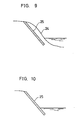
- a slanting continuous trench is excavated in the river bank along a natural bank slope 24, and a slanting bank protection wall 25 is built along the bank by pouring a solidifying solution into this continuous trench and solidifying it therein.
- a cutoff wall is built on the bank slope at the river side in the case that the embankment itself is a permeable bed, whereas a poling board for water cutoff purpose is placed in the case that the foundation portion is a permeable bed.
- a slanting continuous trench is excavated along a bank slope 28 on the embankment, and a slanting cutoff wall 29 is built by pouring a solidifying solution into this trench and solidifying it therein.
- Identified by 30 is an impermeable bed.
- a construction work for preventing the leakage from the river side to the land side can be efficiently performed with a fewer number of construction steps and at a reduced cost.
- slip destruction occurs when the embankment 26 is weak. Further, if the embankment 26 and the foundation portion 27 are both weak, slip destruction occurs, extending over the both as indicated by phantom line in FIG. 12.
- a slanting reinforcement wall 31 is built in the embankment 26 as shown in FIG. 13, or in the foundation portion 27 as shown in FIG. 14, or over the embankment 26 and the foundation portion 27 as shown in FIG. 15.
- a leaning wall effect the weight of the slanting reinforcement wall 31 acts against the earth pressure, can be obtained, thereby enhancing a reinforcing function and a slip destruction preventing effect.
- the slanting cutoff walls 22, 23 are linearly built. Accordingly, in the case that an area is desired to be enclosed by cutoff walls, vertical walls need to be built at the opposite sides with respect to the widthwise directions of the cutoff walls 22, 23. In other words, there is a disadvantage that the cutoff walls cannot be continuously built.
- the solidifying solution cement slurry
- cement slurry is poured into the excavated continuous trench and mixed with the soil available in the original position to build a continuous wall of soil cement.
- concrete may be poured into the excavated trench and solidified therein to build a concrete continuous wall.
- the continuous wall may be built by inserting panels of steel or concrete into the excavated continuous trench while connecting them in a transverse direction.
- the present invention is widely applicable to a variety of purposes other than those mentioned in the foregoing embodiments.
- the backstay 10 is constructed by a hydraulic cylinder and the inclination is adjusted by expanding and contracting this hydraulic cylinder in the foregoing embodiments.
- the backstay 10 may be telescopically constructed merely by an inner tube and an outer tube and the inclination may be adjusted with the help of a crane or like lifting apparatus.
- the slanting continuous trench is excavated by obliquely mounting the chain cutter provided with excavation blades on the running carriage and moving the running carriage in the transverse direction while rotating the cutter with the cutter obliquely placed in the ground, and the wall material is poured into this excavated trench, thereby building the slanting continuous wall in the ground.
- the application of the continuous walls is the use as a cutoff wall having a water cutoff function along vertical direction.
- the continuous wall is built as the repair roof of the underground construction such as a stockroom for radioactive wastes.
- the roof and the floor for preventing the entry of water into the underground stockroom can be efficiently built with a fewer number of construction steps.
- the inverted conical and conical continuous walls are built at the upper and lower side with the apices thereof in contact with each other, and the lower continuous wall can be used as a cutoff bottom wall for pit excavation or an underground roof for an underground stockroom.
- the continuous wall can be built as a water cutoff bottom wall for preventing the entry of groundwater into a trench excavated, e.g. to build a common trench in the ground where free-water elevation is high.
Landscapes
- Engineering & Computer Science (AREA)
- Mining & Mineral Resources (AREA)
- Structural Engineering (AREA)
- Life Sciences & Earth Sciences (AREA)
- General Life Sciences & Earth Sciences (AREA)
- Paleontology (AREA)
- Civil Engineering (AREA)
- General Engineering & Computer Science (AREA)
- Bulkheads Adapted To Foundation Construction (AREA)
Description
Claims (4)
- An underground continuous wall building method, wherein
a chain cutter (2) in which an endless chain (6) provided with excavation blades is fitted between upper and bottom ends of a cutter post (3) is obliquely mounted on a running carriage (1);
a continuous trench (G) is excavated by moving the running carriage (1) in a transverse direction while the cutter (2) is rotated with the cutter (2) obliquely placed in the ground;
and a slanting continuous wall (R1, R2; 32; 35, 36) is built in the ground by pouring a wall material into the thus excavated continuous trench (G) ; characterized in that
the slanting continuous wall (R1, R2; 32; 35, 36) intersects a vertical direction so as to cut off water in a vertical direction, wherein
the slanting continuous trench (G) is so excavated as to have a substantially dihedral cross section and the wall material is poured into this continuous trench (G), wherein
the substantially dihedral cross section of the slanting continuous trench (G) is oriented such as to build a slanting continuous wall which serves as a roof (R1, R2) of an underground construction. - An underground continuous wall building method according to claim 1, wherein a conical continuous trench is excavated by moving the running carriage in circle and the wall material is poured into this continuous trench in order to build a conical continuous wall (36) which serves as a cutoff wall.
- An underground continuous wall building method according to claim 2, wherein an inverted conical continuous trench and a conical continuous trench are excavated at upper and lower sides of the underground in such a manner that the apices of the respective conical continuous trenches are in contact with each other, by moving the running carriage in circle with an intermediate point of a portion of the cutter placed in the ground set as a fixed point.
- An underground continuous wall building method, wherein
a chain cutter (2) in which an endless chain (6) provided with excavation blades is fitted between upper and bottom ends of a cutter post (3) is obliquely mounted on a running carriage (1);
a continuous trench (G) is excavated by moving the running carriage (1) in a transverse direction while the cutter (2) is rotated with the cutter (2) obliquely placed in the ground;
and a slanting continuous wall (22) is built in the ground by pouring a wall material into the thus excavated continuous trench (G); characterized in that
the slanting continuous wall (22) intersects a vertical direction so as to cut off water in a vertical direction, wherein
the slanting continuous trench is so excavated as to extend over two vertical walls (21) built at a specified spacing in the ground and the wall material is poured into this continuous trench in order to build a slanting continuous wall (22) which serves as a cutoff bottom wall for preventing the entry of water into the region between the two vertical walls (21) from below.
Applications Claiming Priority (7)
| Application Number | Priority Date | Filing Date | Title |
|---|---|---|---|
| JP324753/95 | 1995-12-13 | ||
| JP32475395 | 1995-12-13 | ||
| JP32475395 | 1995-12-13 | ||
| JP13236296 | 1996-05-27 | ||
| JP13236296A JP3284047B2 (en) | 1995-12-13 | 1996-05-27 | Construction method of underground diaphragm wall |
| JP132362/96 | 1996-05-27 | ||
| PCT/JP1996/003647 WO1997021877A1 (en) | 1995-12-13 | 1996-12-13 | Method and device for laying underground continuous walls |
Publications (3)
| Publication Number | Publication Date |
|---|---|
| EP0810327A1 EP0810327A1 (en) | 1997-12-03 |
| EP0810327A4 EP0810327A4 (en) | 1999-01-27 |
| EP0810327B1 true EP0810327B1 (en) | 2005-12-07 |
Family
ID=26466951
Family Applications (1)
| Application Number | Title | Priority Date | Filing Date |
|---|---|---|---|
| EP96941865A Expired - Lifetime EP0810327B1 (en) | 1995-12-13 | 1996-12-13 | Method and device for laying underground continuous walls |
Country Status (8)
| Country | Link |
|---|---|
| US (1) | US6139225A (en) |
| EP (1) | EP0810327B1 (en) |
| JP (1) | JP3284047B2 (en) |
| CN (1) | CN1090704C (en) |
| DE (1) | DE69635549T2 (en) |
| DK (1) | DK0810327T3 (en) |
| NO (1) | NO318657B1 (en) |
| WO (1) | WO1997021877A1 (en) |
Families Citing this family (25)
| Publication number | Priority date | Publication date | Assignee | Title |
|---|---|---|---|---|
| WO1998037279A1 (en) * | 1997-02-19 | 1998-08-27 | Yuy Architects And Engineers Co., Ltd. | Method for constructing an underground structure, excavating method, an excavating tool and a reinforceing bar fixing tool therefor |
| US8608410B2 (en) * | 2000-05-31 | 2013-12-17 | Vladimir Anatol Shreider | Apparatus and a method for constructing an underground curved multisectional wall and stratum |
| JP3687575B2 (en) * | 2000-12-28 | 2005-08-24 | コベルコクレーン株式会社 | Construction support method and construction support system for underground continuous wall construction |
| US6840710B2 (en) | 2001-05-15 | 2005-01-11 | Rar Group, Llc | Underground alluvial water storage reservoir and method |
| JP3931769B2 (en) * | 2002-08-30 | 2007-06-20 | コベルコクレーン株式会社 | Underground continuous groove excavation method and underground continuous groove excavator |
| US7192218B2 (en) * | 2004-02-24 | 2007-03-20 | Ps Systems Inc. | Direct recharge injection of underground water reservoirs |
| JP2007211542A (en) * | 2006-02-13 | 2007-08-23 | Mitsubishi Heavy Ind Ltd | Antiseismic structure of quaywall, and its construction method and device |
| US20080073087A1 (en) * | 2006-09-26 | 2008-03-27 | Ps Systems Inc. | Ventilation of underground porosity storage reservoirs |
| US8074670B2 (en) * | 2006-09-26 | 2011-12-13 | PS Systems, Inc. | Maintaining dynamic water storage in underground porosity reservoirs |
| US7972080B2 (en) * | 2007-03-14 | 2011-07-05 | PS Systems, Inc. | Bank-sided porosity storage reservoirs |
| US20090173142A1 (en) * | 2007-07-24 | 2009-07-09 | Ps Systems Inc. | Controlling gas pressure in porosity storage reservoirs |
| US8079163B2 (en) * | 2007-07-30 | 2011-12-20 | Vladimir Anatol Shreider | Excavator and a method for constructing an underground continuous wall |
| US8061065B2 (en) * | 2007-07-30 | 2011-11-22 | Vladimir Anatol Shreider | Apparatus and a method for constructing an underground continuous filling wall and stratum |
| US8337121B2 (en) * | 2009-04-16 | 2012-12-25 | Wayne Poerio | Process for in-ground water collection |
| US20110154618A1 (en) * | 2009-10-28 | 2011-06-30 | Spero Rhonda B | Apparatus For Reducing Theft and Loss of Small Electronic Devices |
| JP5488125B2 (en) * | 2010-03-31 | 2014-05-14 | 新日鐵住金株式会社 | Filling reinforcement structure |
| US8176662B2 (en) | 2010-06-17 | 2012-05-15 | Larry William Peterson | Digging system and method |
| FR2969672B1 (en) * | 2010-12-24 | 2014-02-07 | Soletanche Freyssinet | METHOD OF STRENGTHENING THE RESISTANCE TO THE REVERSAL OF THE FOUNDATIONS OF A PYLONE |
| JP6050172B2 (en) * | 2013-04-03 | 2016-12-21 | 株式会社大林組 | Diagonal retaining wall forming apparatus and construction method of underground structure using the same |
| JP6193720B2 (en) * | 2013-10-22 | 2017-09-06 | 大成建設株式会社 | Ground improvement structure |
| JP6628492B2 (en) * | 2015-04-14 | 2020-01-08 | 大成建設株式会社 | Liquefaction prevention structure |
| US10151074B2 (en) * | 2015-12-15 | 2018-12-11 | Massachusetts Institute Of Technology | Wave damping structures |
| CN108265703B (en) * | 2018-02-12 | 2024-02-23 | 江苏地龙重型机械有限公司 | Cutter device for seamless grooving machine of thin-wall continuous wall |
| CN112816660B (en) * | 2021-01-14 | 2022-04-08 | 浙江大学 | Centrifugal Model Test Device and Method for Studying Environmental Effects of Underground Diaphragm Wall Construction |
| CN118363558B (en) * | 2024-06-20 | 2024-10-11 | 中国水利水电第九工程局有限公司 | Method and system for measuring and displaying limit of underground diaphragm wall |
Family Cites Families (26)
| Publication number | Priority date | Publication date | Assignee | Title |
|---|---|---|---|---|
| US3024546A (en) * | 1960-07-22 | 1962-03-13 | Leonard V Cramer | Side-mounted adjustable ditcher |
| JPS5014803B1 (en) * | 1970-11-30 | 1975-05-30 | ||
| US3768266A (en) * | 1972-05-01 | 1973-10-30 | Stabilization Chem | Shoreline construction for artificial water bodies |
| AT361856B (en) * | 1974-12-17 | 1981-04-10 | Heilmann & Littmann Bau Ag | PROTECTED EARTH DAM AND METHOD FOR THE PRODUCTION THEREOF |
| US3990250A (en) * | 1975-03-17 | 1976-11-09 | Howard William E | Method and apparatus for construction of retaining walls |
| US3986280A (en) * | 1975-04-07 | 1976-10-19 | Johnson Charles F | Apparatus for forming a concrete wall |
| US4164082A (en) * | 1977-10-11 | 1979-08-14 | Watson Gary Q | Excavator for anchor holes |
| US4379658A (en) * | 1980-12-03 | 1983-04-12 | Thatcher Engineering Corporation | Method and apparatus for constructing slurry walls |
| US4877358A (en) * | 1981-04-09 | 1989-10-31 | Finic, B.V. | Method and apparatus of constructing a novel underground impervious barrier |
| JPS61501406A (en) * | 1984-03-12 | 1986-07-10 | ファウンデーション、テクノロジー(オーストラリア)、プロプライエタリ、リミテッド | Structural wall pouring |
| DE3443040C2 (en) * | 1984-11-26 | 1986-12-04 | Gerhard Dr.-Ing. Puch Salzburg Sauer | Process for the production of underground structures using the cover construction method |
| DE3501128C3 (en) * | 1985-01-15 | 1998-11-12 | Keller Grundbau Gmbh | Sealing for the execution of underground structures |
| DE3621884A1 (en) * | 1985-07-22 | 1987-01-29 | Kunz Alfred & Co | Method for constructing and/or driving pipes |
| US4666336A (en) * | 1985-09-26 | 1987-05-19 | Okumura Corporation | Method of and apparatus for building thin lining on tunnel |
| US4871281A (en) * | 1988-02-28 | 1989-10-03 | Justice Donald R | Trenching tool for installing perforated pipe |
| US5074063A (en) * | 1989-06-02 | 1991-12-24 | Pella Engineering & Reseach Corporation | Undercut trenching machine |
| DE3919326A1 (en) * | 1989-06-13 | 1990-12-20 | Holzmann Philipp Ag | NARROW WALL OR SLOT WALL PLACED INTO A SUBSTRATE WITH SEALING WALL MEASUREMENT therein |
| EP0407934B1 (en) * | 1989-07-10 | 1993-10-13 | TREVI S.p.A. | Method for executing monolithic continuous straights or circular structural walls and a machine for realizing such a method |
| JP2654719B2 (en) * | 1990-11-13 | 1997-09-17 | 一利 伊佐地 | Simple underground continuous wall method |
| JPH07113214B2 (en) * | 1992-04-01 | 1995-12-06 | トーメン建機株式会社 | Excavation device for underground wall and construction method using the device |
| JPH0739652B2 (en) * | 1992-04-01 | 1995-05-01 | 北辰工業株式会社 | Underground wall excavator and underground wall construction method |
| US5247743A (en) * | 1992-07-02 | 1993-09-28 | Eagle-Picher Industries, Inc. | Method and apparatus for digging trenches |
| IT1273143B (en) * | 1994-04-14 | 1997-07-04 | Goriziane Spa | PROCEDURE AND EXCAVATION EQUIPMENT FOR THE ACCESS, FOR THE PURPOSE OF MAINTENANCE AND / OR REGENERATION, TO UNDERGROUND PIPES OF OIL PIPES, PIPELINES AND SIMILAR |
| US5497567A (en) * | 1994-05-19 | 1996-03-12 | Gilbert; Jerry F. | Wide trencher with plurality of chain type diggers |
| US5701692A (en) * | 1996-07-03 | 1997-12-30 | Groundwater Control, Inc. | Containment wall installation process and apparatus |
| US5791825A (en) * | 1996-10-04 | 1998-08-11 | Lockheed Martin Idaho Technologies Company | Device and method for producing a containment barrier underneath and around in-situ buried waste |
-
1996
- 1996-05-27 JP JP13236296A patent/JP3284047B2/en not_active Expired - Lifetime
- 1996-12-13 DK DK96941865T patent/DK0810327T3/en active
- 1996-12-13 CN CN96193081.0A patent/CN1090704C/en not_active Expired - Lifetime
- 1996-12-13 WO PCT/JP1996/003647 patent/WO1997021877A1/en not_active Ceased
- 1996-12-13 DE DE69635549T patent/DE69635549T2/en not_active Expired - Fee Related
- 1996-12-13 US US08/894,085 patent/US6139225A/en not_active Expired - Lifetime
- 1996-12-13 EP EP96941865A patent/EP0810327B1/en not_active Expired - Lifetime
-
1997
- 1997-08-06 NO NO19973634A patent/NO318657B1/en unknown
Also Published As
| Publication number | Publication date |
|---|---|
| US6139225A (en) | 2000-10-31 |
| NO318657B1 (en) | 2005-04-25 |
| NO973634L (en) | 1997-08-06 |
| EP0810327A4 (en) | 1999-01-27 |
| JP3284047B2 (en) | 2002-05-20 |
| WO1997021877A1 (en) | 1997-06-19 |
| DE69635549T2 (en) | 2006-08-17 |
| NO973634D0 (en) | 1997-08-06 |
| DE69635549D1 (en) | 2006-01-12 |
| DK0810327T3 (en) | 2006-04-18 |
| EP0810327A1 (en) | 1997-12-03 |
| JPH09221749A (en) | 1997-08-26 |
| CN1090704C (en) | 2002-09-11 |
| CN1185186A (en) | 1998-06-17 |
Similar Documents
| Publication | Publication Date | Title |
|---|---|---|
| US6139225A (en) | Method for building an underground continuous wall | |
| CN103958780A (en) | Constructed using on-site compacted and excavated retaining walls | |
| CN111733842A (en) | Cofferdam construction method and cofferdam structure | |
| CN111155429A (en) | Construction Method of Sand Blowing for Island Building of Bridges in Still Water and Deep Water Areas | |
| CN112663558A (en) | Construction process for excavating weathered rock in inland river harbor pool | |
| HU226433B1 (en) | Foundation slab of underground passage for road | |
| CN112064751A (en) | Deep groove construction method for drainage pipeline | |
| CN117569263A (en) | Dam anti-seepage wall and construction method thereof | |
| JP2004108142A (en) | Method for construction of a control type revetment | |
| JP5099709B2 (en) | Construction method of managed revetment | |
| CN222701024U (en) | Vertical partition wall square forming groove protective cylinder | |
| JP2000291398A (en) | Underground structure and its construction method | |
| JP7597294B1 (en) | Ground improvement methods | |
| KR100476871B1 (en) | Method and construction of underground continuous wall | |
| JP2005133348A (en) | Revetment continuous construction method and river widening method | |
| CN118581916B (en) | Soft soil layer dry dock flood control system and construction process thereof | |
| JP2001011849A (en) | Soil liquefaction prevention structure, its construction method and ground improvement method | |
| JP4606454B2 (en) | Construction method of managed revetment | |
| CN121897064A (en) | A construction method for connecting and interconnecting old and new pipeline networks | |
| Bell et al. | Control of groundwater by exclusion | |
| JP2000110158A (en) | Retaining wall construction method using diagonal walls | |
| JP3424117B2 (en) | Construction method of continuous underground wall | |
| CN118292426A (en) | A vertical barrier wall groove casing and a vertical barrier wall groove construction method | |
| JP3248102B2 (en) | Ground improvement method for soft ground | |
| JPH0465932B2 (en) |
Legal Events
| Date | Code | Title | Description |
|---|---|---|---|
| PUAI | Public reference made under article 153(3) epc to a published international application that has entered the european phase |
Free format text: ORIGINAL CODE: 0009012 |
|
| AK | Designated contracting states |
Kind code of ref document: A1 Designated state(s): DE DK FI FR GB SE |
|
| 17P | Request for examination filed |
Effective date: 19971104 |
|
| A4 | Supplementary search report drawn up and despatched |
Effective date: 19981214 |
|
| AK | Designated contracting states |
Kind code of ref document: A4 Designated state(s): DE DK FI FR GB SE |
|
| RHK1 | Main classification (correction) |
Ipc: E02D 5/18 |
|
| 17Q | First examination report despatched |
Effective date: 20021202 |
|
| GRAP | Despatch of communication of intention to grant a patent |
Free format text: ORIGINAL CODE: EPIDOSNIGR1 |
|
| GRAS | Grant fee paid |
Free format text: ORIGINAL CODE: EPIDOSNIGR3 |
|
| GRAA | (expected) grant |
Free format text: ORIGINAL CODE: 0009210 |
|
| RAP1 | Party data changed (applicant data changed or rights of an application transferred) |
Owner name: JAPAN AS REPRESENTED BY A GENERAL MANAGER, KANTORE Owner name: KOBELCO CRANES CO., LTD. |
|
| AK | Designated contracting states |
Kind code of ref document: B1 Designated state(s): DE DK FI FR GB SE |
|
| REG | Reference to a national code |
Ref country code: GB Ref legal event code: FG4D |
|
| REF | Corresponds to: |
Ref document number: 69635549 Country of ref document: DE Date of ref document: 20060112 Kind code of ref document: P |
|
| REG | Reference to a national code |
Ref country code: SE Ref legal event code: TRGR |
|
| REG | Reference to a national code |
Ref country code: DK Ref legal event code: T3 |
|
| ET | Fr: translation filed | ||
| PLBE | No opposition filed within time limit |
Free format text: ORIGINAL CODE: 0009261 |
|
| STAA | Information on the status of an ep patent application or granted ep patent |
Free format text: STATUS: NO OPPOSITION FILED WITHIN TIME LIMIT |
|
| 26N | No opposition filed |
Effective date: 20060908 |
|
| PGFP | Annual fee paid to national office [announced via postgrant information from national office to epo] |
Ref country code: FR Payment date: 20061215 Year of fee payment: 11 |
|
| PGFP | Annual fee paid to national office [announced via postgrant information from national office to epo] |
Ref country code: GB Payment date: 20061218 Year of fee payment: 11 |
|
| PGFP | Annual fee paid to national office [announced via postgrant information from national office to epo] |
Ref country code: DE Payment date: 20070130 Year of fee payment: 11 |
|
| PGFP | Annual fee paid to national office [announced via postgrant information from national office to epo] |
Ref country code: DK Payment date: 20071220 Year of fee payment: 12 |
|
| PGFP | Annual fee paid to national office [announced via postgrant information from national office to epo] |
Ref country code: FI Payment date: 20071217 Year of fee payment: 12 |
|
| PGFP | Annual fee paid to national office [announced via postgrant information from national office to epo] |
Ref country code: SE Payment date: 20071220 Year of fee payment: 12 |
|
| GBPC | Gb: european patent ceased through non-payment of renewal fee |
Effective date: 20071213 |
|
| PG25 | Lapsed in a contracting state [announced via postgrant information from national office to epo] |
Ref country code: DE Free format text: LAPSE BECAUSE OF NON-PAYMENT OF DUE FEES Effective date: 20080701 |
|
| REG | Reference to a national code |
Ref country code: FR Ref legal event code: ST Effective date: 20081020 |
|
| PG25 | Lapsed in a contracting state [announced via postgrant information from national office to epo] |
Ref country code: GB Free format text: LAPSE BECAUSE OF NON-PAYMENT OF DUE FEES Effective date: 20071213 |
|
| PG25 | Lapsed in a contracting state [announced via postgrant information from national office to epo] |
Ref country code: FR Free format text: LAPSE BECAUSE OF NON-PAYMENT OF DUE FEES Effective date: 20071231 |
|
| PG25 | Lapsed in a contracting state [announced via postgrant information from national office to epo] |
Ref country code: FI Free format text: LAPSE BECAUSE OF NON-PAYMENT OF DUE FEES Effective date: 20081213 |
|
| REG | Reference to a national code |
Ref country code: DK Ref legal event code: EBP |
|
| EUG | Se: european patent has lapsed | ||
| PG25 | Lapsed in a contracting state [announced via postgrant information from national office to epo] |
Ref country code: DK Free format text: LAPSE BECAUSE OF NON-PAYMENT OF DUE FEES Effective date: 20090105 |
|
| PG25 | Lapsed in a contracting state [announced via postgrant information from national office to epo] |
Ref country code: SE Free format text: LAPSE BECAUSE OF NON-PAYMENT OF DUE FEES Effective date: 20081214 |