EP0810099A2 - Un tambour d'enregistrement d'images absorbant des lasers pour balayeurs - Google Patents
Un tambour d'enregistrement d'images absorbant des lasers pour balayeurs Download PDFInfo
- Publication number
- EP0810099A2 EP0810099A2 EP97201487A EP97201487A EP0810099A2 EP 0810099 A2 EP0810099 A2 EP 0810099A2 EP 97201487 A EP97201487 A EP 97201487A EP 97201487 A EP97201487 A EP 97201487A EP 0810099 A2 EP0810099 A2 EP 0810099A2
- Authority
- EP
- European Patent Office
- Prior art keywords
- imaging
- medium
- receptacle
- laser beam
- drum
- Prior art date
- Legal status (The legal status is an assumption and is not a legal conclusion. Google has not performed a legal analysis and makes no representation as to the accuracy of the status listed.)
- Withdrawn
Links
Images


Classifications
-
- B—PERFORMING OPERATIONS; TRANSPORTING
- B41—PRINTING; LINING MACHINES; TYPEWRITERS; STAMPS
- B41J—TYPEWRITERS; SELECTIVE PRINTING MECHANISMS, i.e. MECHANISMS PRINTING OTHERWISE THAN FROM A FORME; CORRECTION OF TYPOGRAPHICAL ERRORS
- B41J11/00—Devices or arrangements of selective printing mechanisms, e.g. ink-jet printers or thermal printers, for supporting or handling copy material in sheet or web form
- B41J11/02—Platens
- B41J11/04—Roller platens
- B41J11/057—Structure of the surface
-
- B—PERFORMING OPERATIONS; TRANSPORTING
- B41—PRINTING; LINING MACHINES; TYPEWRITERS; STAMPS
- B41J—TYPEWRITERS; SELECTIVE PRINTING MECHANISMS, i.e. MECHANISMS PRINTING OTHERWISE THAN FROM A FORME; CORRECTION OF TYPOGRAPHICAL ERRORS
- B41J2/00—Typewriters or selective printing mechanisms characterised by the printing or marking process for which they are designed
- B41J2/435—Typewriters or selective printing mechanisms characterised by the printing or marking process for which they are designed characterised by selective application of radiation to a printing material or impression-transfer material
- B41J2/475—Typewriters or selective printing mechanisms characterised by the printing or marking process for which they are designed characterised by selective application of radiation to a printing material or impression-transfer material for heating selectively by radiation or ultrasonic waves
Definitions
- the invention relates generally to the field of lathe bed scanners utilizing a rotating imaging drum for maintaining the positional relationship of donor element and writing elements during the writing process and, more particularly, to such imaging drums having a laser-absorbent coating for substantially eliminating a undesirable, reflected laser beam which causes artifacts on the writing element during writing.
- Color-proofing is the procedure used by the printing industry for creating representative images that replicate the appearance of printed images without the cost and time required to actually set up a high-speed, high-volume printing press to print an example of the images intended.
- One such color proofer is a lathe bed scanner which utilizes a thermal printer having half-tone capabilities. This printer is arranged to form an image on a thermal print medium, or writing element, in which a donor transfers a dye to the writing element upon a sufficient amount of thermal energy.
- This printer includes a plurality of diode lasers which can be individually modulated to supply energy to selected areas of the medium in accordance with an information signal.
- a print-head includes one end of a fiber optic array having a plurality of optical fibers that are coupled to the diode lasers for transmitting the signals from the laser to the print head.
- the writing element is supported on a rotatable imaging drum, and the print-head with the fiber optic array is movable relative to the longitudinal axis of the drum.
- the dye is transferred to the writing element as the radiation, transferred from the diode lasers to the donor element by the optical fibers, is converted to thermal energy in the donor element.
- the cylindrical-shaped imaging drum includes a hollowed-out interior portion and further includes a plurality of holes extending through its housing for permitting a vacuum to be applied from the interior of the drum to the receiver and writing elements for maintaining their position as the drum is rotated.
- the print head emits the laser beam as it moves along the drum.
- the beam then passes through the donor element for causing the dye to transfer to the writing element.
- a portion of the laser beam, or a residual beam, remains because of imperfect thermal transfer, and this residual beam is consequently transferred through the writing element and onto the imaging drum.
- the present invention is directed to overcoming one or more of the problems set forth above.
- the invention resides in an imaging processor for receiving a medium for processing.
- the processor comprises a print head for providing and for directing a laser beam.
- An imaging receptacle positioned adjacent the print head for receiving the medium which is exposed to the medium the laser beam which emits out of the print head and a portion of the laser beam passes through the medium and onto the imaging drum.
- a laser-absorbent coating is coated onto the imaging drum for absorbing the laser beam that is received by the imaging receptacle for substantially eliminating undesirable artifacts.
- a lathe bed scanner 10 of the present invention having a housing 15 for forming a protective cover.
- a movable, hinged door 20 is attached to a front portion of the housing 15 for permitting access to two media trays, a lower tray 30a and upper tray 30b, that are positioned in an interior portion of the housing 15 for supporting receiver material 40, typically paper, thereon.
- receiver material 40 typically paper
- the lower media tray 30a includes a cam 50a for lifting the paper 40 upwardly toward a rotatable, lower media roller 60a and, ultimately, toward a second rotatable, upper media roller 60b which, when both are rotated, permits the receiver material 40 to be pulled upwardly towards a media guide 70.
- the upper media tray 30b also includes a cam 50b for lifting the receiver material 40 toward the upper media roller 60b which directs it towards the media guide 70.
- the movable media guide 70 directs the receiver material 40 under a pair of rollers 80 which engages the receiver material 40 for assisting the upper media roller 60b in directing it onto a staging tray 90.
- the media guide 70 is attached and hinged to the interior of the housing 15 at one end, and is uninhibited at its other end for permitting multiple positioning of the media guide 70.
- the media guide 70 then rotates its uninhibited end downwardly, as illustrated by the solid line, and the direction of rotation of the upper media roller 60b is reversed for forcing the receiver material 40 resting on the staging tray 90 back under the rollers 80, upwardly through an entrance passageway 100 and around a rotatable imaging drum 110.
- each roll includes a donor material 120 of a different color, typically black, yellow, magenta and cyan. These donor materials are ultimately cut into sheets and passed to the imaging drum for forming a medium from which dyes imbedded therein are passed to the receiver material resting thereon, which process is described in detail herein below.
- a drive mechanism 140 is attached to each roll 120, and includes three rollers 150 through which the donor material 120 of interest is rolled upwardly into a knife assembly 160.
- the rollers 150 cease driving the donor material 120 and two blades 170 positioned at the bottom portion of the knife assemble cut the donor material 120 into a sheet.
- the media rollers 60a and 60b and media guide 70 then pass the donor material 120 onto the drum 110 and in registration with the receiver material 40 using the same process as described above for passing the receiver material 40 onto the drum 110.
- the donor material 120 rests atop the receiver material 40 with a narrow gap between the two created by microbeads imbedded into the receiver material 40.
- a laser assembly 180 includes twenty lasers 185 in its interior, and these lasers are connected via fiber optic cables 187 to a coupling head 190 and ultimately to a write head 200.
- the write head 200 creates thermal energy from the signal received from the lasers 185 causing the donor material 120 to pass its dye across the gap to the receiver material 40.
- the write head 200 is attached to a lead screw 210 via a nut (not shown in Fig. 1) for permitting it to move axially along the longitudinal axis of the drum 110 for writing data onto the receiver material 40.
- the drum 110 rotates at a constant velocity, and the write head 200 begins at one end of the receiver material 40 and traverses the entire length of the receiver material 40 for completing the transfer process for the particular donor material resting on the receiver material 40.
- the donor material 120 is then transferred from the drum 110 and out of the housing 15 via a skive or ejection chute 210.
- the donor material eventually comes to rest on a donor material tray 212 for permitting removal by a user.
- the above-described process is then repeated for the other three rolls of donor material.
- the receiver material 40 is transported via a transport mechanism 220 through an entrance door 230 and into a dye binding assembly 240 where it rests against an exit door 250.
- the entrance door 230 is opened for permitting the receiver material 40 to enter into the dye binding assembly 240, and shuts once it comes to rest in the dye binding assembly 240.
- the dye binding assembly 240 heats the receiver material 40 for further binding the transferred dye on the receiver material 40 and for sealing the microbeads thereon.
- the exit door 250 is opened and the receiver material 40 with the image thereon passes out of the housing 15 and comes to rest against a stop 260.
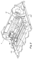
- FIG. 2 there is illustrated a perspective view of the imaging drum 110 and write head 200 of the lathe bed scanner 10.
- the imaging drum 110 is mounted for rotation about an axis (x) in a frame support 270.
- the write head 200 is movable with respect to the imaging drum 110, and is arranged to direct a beam of actinic light to the donor material 120 (shown in Fig. 1).
- the write head 200 contains therein a plurality of writing elements (not shown) which can be individually modulated by electronic signals from the laser diodes 185, which signals are representative of the shape and color of the original image, so that each dye is heated to cause volatilization only in those areas in which its presence is required on the receiver material 40 to reconstruct the color of the original object.
- the write head 200 is mounted on a movable translator member 280 which, in turn, is supported for low friction slidable movement on bars 290 and 300.
- the bars 290 and 300 are sufficiently rigid so that they do not sag or distort between the mounting points at their ends and are arranged as parallel as possible with the axis (x) of the imaging drum 110.
- the upper bar 300 is arranged to locate the axis of the writing head 200 precisely on the axis (x) of the drum 110 with the axis of the writing head perpendicular to the drum axis (x).
- the upper bar 300 locates the translator member 280 in the vertical and the horizontal directions with respect to the axis of the drum 110.
- the lower bar 290 locates the translator member 280 only with respect to rotation of the translator about the bar 290 so that there is no over-constraint of the translator member 280 which might cause it to bind, chatter, or otherwise impart undesirable vibration to the writing head 200 during the generation of an image.
- the imaging drum 110 having a cylindrical-shaped housing 305 partially and respectively enclosed on both ends by two plates 310.
- the housing 305 further includes a hollowed-out interior (annular shaped in vertical cross section) for permitting a vacuum to be applied from its interior portion.
- a plurality of holes 320 extend entirely through the housing 305 for permitting the vacuum to maintain the donor 120 and writing elements 40 thereon during rotation of the drum 110.
- a diamond-like carbon (DLC) coating 330 which is commercially available from Diamonex, is applied on the housing 305 by a well known RF (radio frequency) sputtering technique.
- the coating 330 absorbs a residual laser beam that is not absorbed by the writing element and would otherwise reflect off the drum surface if not absorbed. This absorption substantially eliminates a undesirable, reflected laser beam which typically creates artifacts on the writing element during writing process.
- the coating 330 is preferably coated to a thickness of between 5000 and 50,000 angstroms, and includes a chemical structure with material properties similar, but not identical, to diamond. It is instructive to note that this type of coating 330 will absorb electromagnetic irradiation in the 600 to 900 nanometer range, which includes the infrared range; scanners typically write in the 800 to 900 nanometer range.
- the coating 330 may also be applied by other well known techniques, such as ion beam deposition or plasma assisted chemical vapor deposition.
- RF sputtering is preferred because it requires a lower application temperature and yields a strong bond with the surface of the drum 110.
- the imaging drum wherein said coating is diamond-like carbon.
- the imaging drum wherein said coating absorbs electromagnetic irradiation in the range of substantially 600 to 900 nanometers.
- imaging drum wherein said imaging drum includes a plurality of perforations for permitting a vacuum to retain the medium onto said imaging drum.
Landscapes
- Health & Medical Sciences (AREA)
- General Health & Medical Sciences (AREA)
- Toxicology (AREA)
- Electronic Switches (AREA)
- Handling Of Cut Paper (AREA)
- Thermal Transfer Or Thermal Recording In General (AREA)
- Facsimile Scanning Arrangements (AREA)
Applications Claiming Priority (2)
| Application Number | Priority Date | Filing Date | Title |
|---|---|---|---|
| US65378496A | 1996-05-28 | 1996-05-28 | |
| US653784 | 2000-09-01 |
Publications (2)
| Publication Number | Publication Date |
|---|---|
| EP0810099A2 true EP0810099A2 (fr) | 1997-12-03 |
| EP0810099A3 EP0810099A3 (fr) | 1998-07-22 |
Family
ID=24622298
Family Applications (1)
| Application Number | Title | Priority Date | Filing Date |
|---|---|---|---|
| EP97201487A Withdrawn EP0810099A3 (fr) | 1996-05-28 | 1997-05-16 | Un tambour d'enregistrement d'images absorbant des lasers pour balayeurs |
Country Status (2)
| Country | Link |
|---|---|
| EP (1) | EP0810099A3 (fr) |
| JP (1) | JPH1052929A (fr) |
Cited By (1)
| Publication number | Priority date | Publication date | Assignee | Title |
|---|---|---|---|---|
| US7380499B2 (en) * | 2003-12-25 | 2008-06-03 | Konica Minolta Medical & Graphic, Inc. | Image recording apparatus and printing plate material |
Citations (7)
| Publication number | Priority date | Publication date | Assignee | Title |
|---|---|---|---|---|
| JPS57165845A (en) * | 1981-04-06 | 1982-10-13 | Hitachi Ltd | Electrophotographic recorder |
| US4957378A (en) * | 1986-09-09 | 1990-09-18 | Ricoh Company, Ltd. | Printing-plate preparation apparatus employed in screen printing machine including a non-adhesive platen surface and a manuscript reading unit. |
| EP0465984A1 (fr) * | 1990-07-04 | 1992-01-15 | Matsushita Electric Industrial Co., Ltd. | Corps photosensible utilisé en électrophotographie |
| US5170178A (en) * | 1991-03-26 | 1992-12-08 | Minolta Camera Kabushiki Kaisha | Thermal transfer recording apparatus |
| EP0529561A2 (fr) * | 1991-08-23 | 1993-03-03 | Eastman Kodak Company | Support de diode laser avec dispositif de mise au point automatique |
| EP0577527A1 (fr) * | 1992-06-29 | 1994-01-05 | Eastman Kodak Company | Support donneur et support recepteur sans contacts pour l'impression thermique |
| JPH0672030A (ja) * | 1992-08-28 | 1994-03-15 | Canon Inc | 画像形成方法及び画像形成装置 |
-
1997
- 1997-05-16 EP EP97201487A patent/EP0810099A3/fr not_active Withdrawn
- 1997-05-21 JP JP13124597A patent/JPH1052929A/ja active Pending
Patent Citations (7)
| Publication number | Priority date | Publication date | Assignee | Title |
|---|---|---|---|---|
| JPS57165845A (en) * | 1981-04-06 | 1982-10-13 | Hitachi Ltd | Electrophotographic recorder |
| US4957378A (en) * | 1986-09-09 | 1990-09-18 | Ricoh Company, Ltd. | Printing-plate preparation apparatus employed in screen printing machine including a non-adhesive platen surface and a manuscript reading unit. |
| EP0465984A1 (fr) * | 1990-07-04 | 1992-01-15 | Matsushita Electric Industrial Co., Ltd. | Corps photosensible utilisé en électrophotographie |
| US5170178A (en) * | 1991-03-26 | 1992-12-08 | Minolta Camera Kabushiki Kaisha | Thermal transfer recording apparatus |
| EP0529561A2 (fr) * | 1991-08-23 | 1993-03-03 | Eastman Kodak Company | Support de diode laser avec dispositif de mise au point automatique |
| EP0577527A1 (fr) * | 1992-06-29 | 1994-01-05 | Eastman Kodak Company | Support donneur et support recepteur sans contacts pour l'impression thermique |
| JPH0672030A (ja) * | 1992-08-28 | 1994-03-15 | Canon Inc | 画像形成方法及び画像形成装置 |
Non-Patent Citations (2)
| Title |
|---|
| PATENT ABSTRACTS OF JAPAN vol. 007, no. 006 (P-167), 11 January 1983 & JP 57 165845 A (HITACHI SEISAKUSHO KK;OTHERS: 01), 13 October 1982, * |
| PATENT ABSTRACTS OF JAPAN vol. 018, no. 319 (M-1623), 17 June 1994 & JP 06 072030 A (CANON INC), 15 March 1994, * |
Cited By (1)
| Publication number | Priority date | Publication date | Assignee | Title |
|---|---|---|---|---|
| US7380499B2 (en) * | 2003-12-25 | 2008-06-03 | Konica Minolta Medical & Graphic, Inc. | Image recording apparatus and printing plate material |
Also Published As
| Publication number | Publication date |
|---|---|
| JPH1052929A (ja) | 1998-02-24 |
| EP0810099A3 (fr) | 1998-07-22 |
Similar Documents
| Publication | Publication Date | Title |
|---|---|---|
| JPH05284303A (ja) | レーザサーマルプリンタ装置およびその印字方法 | |
| JPH07205507A (ja) | 周面に軸方向の平坦面を持つ画像形成ドラム | |
| JPH05229206A (ja) | 重ね合わされたシートを真空ドラムに装着および除去する方法および装置 | |
| JP2937638B2 (ja) | ロール媒体供給装置を備えるレーザサーマルプリンタ | |
| JP3337495B2 (ja) | 複数室がある画像形成ドラム | |
| US5838345A (en) | Apparatus for maintaining the positional relationship of a print head | |
| US5909237A (en) | Exposing imagesetter recording film on a color-proofing apparatus | |
| JPH05246053A (ja) | ドラム表面の位置確認印 | |
| EP0810099A2 (fr) | Un tambour d'enregistrement d'images absorbant des lasers pour balayeurs | |
| EP0529054A1 (fr) | Focalisation d'un rayon d'ecriture utilisant une lumiere de longueur d'onde differente. | |
| US6034713A (en) | Image processor having magnetically attached print head | |
| JPH05201103A (ja) | ポジティブエアフロー付レーザサーマルプリンタ | |
| JPH05254189A (ja) | ドラム周囲にシート保持リセス(凹み部)を有する画像形成減圧吸引ドラム | |
| US6034714A (en) | Method and apparatus for preventing transient oscillations in a focusing beam of scanners | |
| US5818497A (en) | Apparatus for magnetically coupling a lead screw to a print head | |
| US6037960A (en) | Direct write plates on a thermal dye transfer apparatus | |
| US5812175A (en) | Laser thermal printer with reversible imaging drum rotation for printing mirror images | |
| JPH05201035A (ja) | 書き込みヘッド上に載置される合焦用レーザダイオード | |
| JP2883499B2 (ja) | 素材供給カルーゼル(回転ラック) | |
| US5146241A (en) | Automatic cut-out for auto-focus device | |
| US6174045B1 (en) | Method and apparatus for printing color images using an inkjet printhead and a laser thermal printhead | |
| US5771059A (en) | Apparatus for preventing axial movement of a lead screw | |
| US5949463A (en) | Image processor for processing various sizes of a processing medium | |
| JPH05229148A (ja) | いらないシートから画像が形成されたシートを仕分けする方法及び装置 | |
| US5291217A (en) | Method and apparatus for producing thermal slide transparencies |
Legal Events
| Date | Code | Title | Description |
|---|---|---|---|
| PUAI | Public reference made under article 153(3) epc to a published international application that has entered the european phase |
Free format text: ORIGINAL CODE: 0009012 |
|
| AK | Designated contracting states |
Kind code of ref document: A2 Designated state(s): DE FR GB |
|
| PUAL | Search report despatched |
Free format text: ORIGINAL CODE: 0009013 |
|
| AK | Designated contracting states |
Kind code of ref document: A3 Designated state(s): DE FR GB |
|
| STAA | Information on the status of an ep patent application or granted ep patent |
Free format text: STATUS: THE APPLICATION HAS BEEN WITHDRAWN |
|
| 18W | Application withdrawn |
Withdrawal date: 19980911 |