EP0809978A2 - Dispensing device - Google Patents
Dispensing device Download PDFInfo
- Publication number
- EP0809978A2 EP0809978A2 EP97104175A EP97104175A EP0809978A2 EP 0809978 A2 EP0809978 A2 EP 0809978A2 EP 97104175 A EP97104175 A EP 97104175A EP 97104175 A EP97104175 A EP 97104175A EP 0809978 A2 EP0809978 A2 EP 0809978A2
- Authority
- EP
- European Patent Office
- Prior art keywords
- base film
- marking
- root canal
- tooth root
- receptacles
- Prior art date
- Legal status (The legal status is an assumption and is not a legal conclusion. Google has not performed a legal analysis and makes no representation as to the accuracy of the status listed.)
- Withdrawn
Links
Images


Classifications
-
- A—HUMAN NECESSITIES
- A61—MEDICAL OR VETERINARY SCIENCE; HYGIENE
- A61C—DENTISTRY; APPARATUS OR METHODS FOR ORAL OR DENTAL HYGIENE
- A61C5/00—Filling or capping teeth
- A61C5/40—Implements for surgical treatment of the roots or nerves of the teeth; Nerve needles; Methods or instruments for medication of the roots
- A61C5/44—Means for controlling working depth, e.g. supports or boxes with depth-gauging means, stop positioners or files with adjustably-mounted handles
Definitions
- the invention relates to a dispenser for marking discs for limiting the depth of penetration of tooth root canal preparation instruments and the like.
- tooth root canal preparation instruments are only allowed to penetrate into the tooth root to a certain depth
- marking discs made of silicone are used as stoppers to mark the permissible penetration depth up to which drilling is permitted. These markers are pulled up to the corresponding point on the tooth root canal preparation instruments.
- DE 3 419 712 C2 describes a dispensing device for marking disks of this type, which is intended to facilitate the mounting of the marking disks on a tooth root canal preparation instrument.
- This known dispenser device has a receiving chamber in which the marking disks are accommodated in an arbitrary arrangement and which is connected to a cavity, the height of which essentially corresponds to the thickness of the marking disks, thereby separating the Marking disks are possible in order to arrange them individually in a specific position at an opening of the dispensing device, at which they can be drawn by impaling on a tooth root canal preparation instrument.
- the object on which the invention is based is to create a dispenser device of the type mentioned at the outset which is simple in construction and therefore associated with low costs and which, in particular, allows the marking disks to be sterilized and kept sterile.
- a base film made of a plastic material which has such a strength that the base film can be pierced by a tooth root canal preparation instrument, deep-drawn receptacles for the marking disks being formed in the base film in such a way that the marking disks in a to the base film parallel plane are included, and released a cover that is detachably connected to the base film with this.
- the marking disks can thus be accommodated in a defined position in their respective receptacles, so that the marking disks are uncovered by detaching the cover from the base film and can thus be fitted onto a tooth root canal preparation instrument by using a marking disk and the base film on the pierces the associated receptacle until the marking disc is pulled up to the desired location on the tooth root canal preparation instrument.
- the dispenser device according to the invention is simple to manufacture and at low cost.
- the cover is particularly designed so that it the receptacles filled with the marking disks are only released step by step, for example in rows or individually, advantageously ensuring that the remaining marking disks remain sterile.
- the dispenser device for marking discs 3 shown in FIG. 1 for limiting the penetration depth of tooth root canal preparation instruments comprises a base film 1 made of a plastic material such as polystyrene, which can be pierced by a number root canal preparation instrument and in which deep-drawn receptacles 2 are designed such that the marking discs lie individually therein can be included.
- the marking disks 3 thus lie flat in a plane that is parallel to the plane of the base film 1.
- a cover i.e. In the embodiment shown in FIG. 1, a peel-off film 4 is arranged above the arrangement of the base film 1 with the marking disks 3 located in the receptacles 2.
- the peel-off film 4 consists, for example, of aluminum with a thin sealing layer and is connected to the base film 1 by the action of pressure and heat.
- the recordings 2 for the marking discs 3 arranged in parallel rows or columns. If, in the manner shown in FIG. 2, the peel-off film 4 is provided with tear lines which run between the rows or columns of the receptacles 2, it is possible to tear the marking disks 3 individually along a row or column of the receptacles 2 only by tearing them open remove without exposing the remaining marking disks in their receptacles 2, which therefore remain sterile in their receptacles 2.
- this is facilitated by a tongue-like design of the base film 1 and / or the peel film 4 on one edge of the dispenser device.
- the base film 1 is first deep-drawn and provided with the receptacles 2, the marking disks 3 are then inserted into the receptacles 2, which can be accompanied by a sterilization process, and the release film 4 is then applied and sealed.
- the peel-off film 4 is torn open and pulled off along a row or column of the receptacles 2 in the manner shown in FIG. 2 until at least one receptacle 2 with the marking disk 3 contained therein is exposed.
- the marking disc 3 and the base film 1 can then be pierced at the bottom of the receptacle 2 due to the defined position of the marking disc 3 with a tooth root canal preparation element 5, and the marking disc 3 can thereby be pushed onto the tooth root canal preparation instrument 5 up to the desired one Place to be raised.
- the defined position of the marking disk 3 in the receptacle 2 ensures that the tooth root canal preparation instrument 5 punctures it in the correct position, this being due to the fact that this can be done without the marking disk by hand touch, sterile is possible.
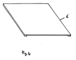
- Fig. 4 shows the cover in a further embodiment.
- the cover consists of a slide 6 which is pushed over the base film 1 after the receptacles 2 of the base film 1 have been filled with the marking disks 3.
- the receptacles 2 with the marking disks 3 arranged therein can then be exposed in rows or columns, so that individual marking disks 3 can be picked up by a tooth root canal preparation instrument. Only one row of the marking disks 3 is uncovered, the rest of the marking disks 3 remain covered.
Landscapes
- Health & Medical Sciences (AREA)
- Engineering & Computer Science (AREA)
- Biomedical Technology (AREA)
- Neurology (AREA)
- Neurosurgery (AREA)
- Nuclear Medicine, Radiotherapy & Molecular Imaging (AREA)
- Surgery (AREA)
- Oral & Maxillofacial Surgery (AREA)
- Dentistry (AREA)
- Epidemiology (AREA)
- Life Sciences & Earth Sciences (AREA)
- Animal Behavior & Ethology (AREA)
- General Health & Medical Sciences (AREA)
- Public Health (AREA)
- Veterinary Medicine (AREA)
- Dental Tools And Instruments Or Auxiliary Dental Instruments (AREA)
Abstract
Spendervorrichtung für Markierungsscheiben 3 zum Begrenzen der Eindringtiefe von Zahnwurzelkanalaufbereitungsinstrumenten. Die Spendervorrichtung besteht aus einer Basisfolie 1 aus einem Kunststoffmaterial, das eine derartige Festigkeit hat, daß die Basisfolie 1 von einem Zahnwurzelkanalaufbereitungsinstrument durchstoßen werden kann. In der Basisfolie 1 sind tiefgezogene Aufnahmen 2 für die Markierungsscheiben 3 ausgebildet und zwar derart, daß die Markierungsscheiben 3 in den Aufnahmen 2 in einer zur Basisfolie 1 parallelen Ebene liegend aufgenommen sind. Über der Basisfolie 1 und mit dieser verbunden ist eine Abziehfolie 4 vorgesehen, die insbesondere stückweise von der Basisfolie so abziehbar ist, daß nacheinander die in Reihen oder Spalten angeordneten Aufnahmen 2 freigelegt werden. Mit einem Zahnwurzelkanalaufbereitungsinstrument können dann die freiliegende Markierungsscheibe 3 sowie die darunter liegende Basisfolie 1 in der Aufnahme 2 durchstoßen werden, bis die Markierungsscheibe 3 an der gewünschten Stelle am Zahnwurzelkanalaufbereitungsinstrument angeordnet ist.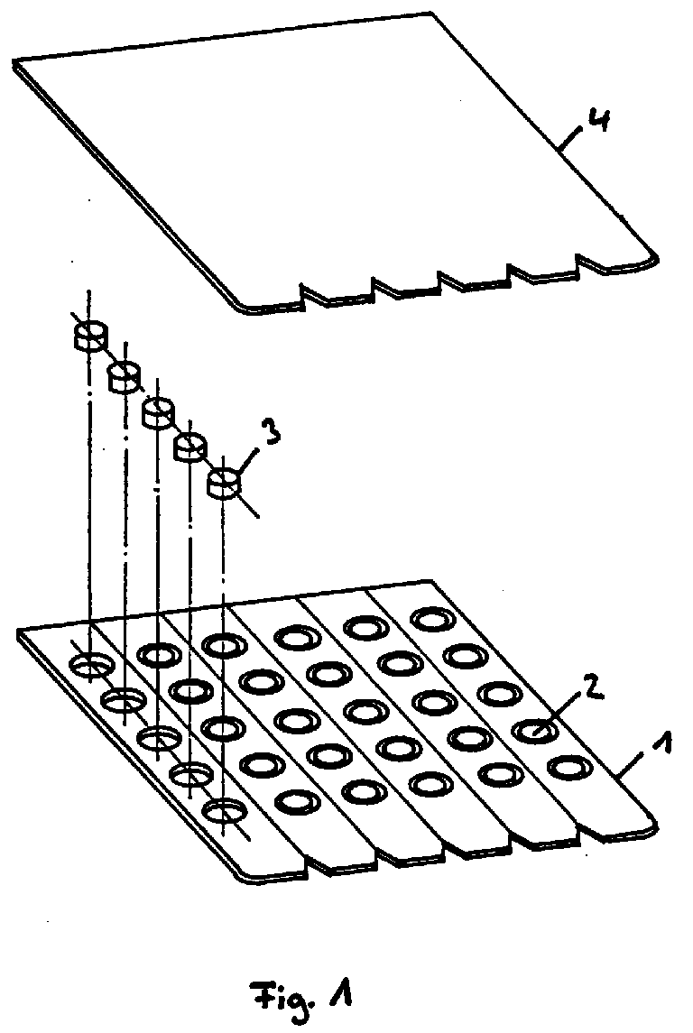
Description
Die Erfindung betrifft eine Spendervorrichtung für Markierungsscheiben zum Begrenzen der Eindringtiefe von Zahnwurzelkanalaufbereitungsinstrumenten und dergleichen.The invention relates to a dispenser for marking discs for limiting the depth of penetration of tooth root canal preparation instruments and the like.
Da Zahnwurzelkanalaufbereitungsinstrumente nur bis zu einer gewissen Tiefe in die Zahnwurzel eindringen dürfen, werden Markierungsscheiben aus beispielsweise Silicon als Stopper dazu benutzt, die zulässige Eindringtiefe zu markieren, bis zu welcher gebohrt werden darf. Diese Markierungsscheiben werden bis zu der entsprechenden Stelle auf die Zahnwurzelkanalaufbereitungsinstrumente aufgezogen.Since tooth root canal preparation instruments are only allowed to penetrate into the tooth root to a certain depth, marking discs made of silicone, for example, are used as stoppers to mark the permissible penetration depth up to which drilling is permitted. These markers are pulled up to the corresponding point on the tooth root canal preparation instruments.
Eine Spendervorrichtung für derartige Markierungsscheiben, die das Aufziehen der Markierungsscheiben auf ein Zahnwurzelkanalaufbereitungsinstrument erleichtern soll, ist in der DE 3 419 712 C2 beschrieben. Diese bekannte Spendervorrichtung weist eine Aufnahmekammer auf, in der die Markierungsscheiben in willkürlicher Anordnung aufgenommen sind und die mit einem Hohlraum in Verbindung steht, dessen Höhe im wesentlichen der Dicke der Markierungsscheiben entspricht, wodurch eine Vereinzelung der Markierungsscheiben möglich ist, um diese einzeln in einer bestimmten Lage an einer Öffnung der Spendervorrichtung anzuordnen, an der sie durch Aufspießen auf ein Zahnwurzelkanalaufbereitungsinstrument aufgezogen werden können.DE 3 419 712 C2 describes a dispensing device for marking disks of this type, which is intended to facilitate the mounting of the marking disks on a tooth root canal preparation instrument. This known dispenser device has a receiving chamber in which the marking disks are accommodated in an arbitrary arrangement and which is connected to a cavity, the height of which essentially corresponds to the thickness of the marking disks, thereby separating the Marking disks are possible in order to arrange them individually in a specific position at an opening of the dispensing device, at which they can be drawn by impaling on a tooth root canal preparation instrument.
Die der Erfindung zugrunde liegende Aufgabe besteht dem gegenüber darin, eine Spendervorrichtung der eingangs genannten Art zu schaffen, die in ihrem Aufbau einfach und daher mit geringen Kosten verbunden ist und die es insbesondere erlaubt, die Markierungsscheiben zu sterilisieren und steril aufzubewahren.The object on which the invention is based, on the other hand, is to create a dispenser device of the type mentioned at the outset which is simple in construction and therefore associated with low costs and which, in particular, allows the marking disks to be sterilized and kept sterile.
Diese Aufgabe wird gemäß der Erfindung durch eine Basisfolie aus einem Kunststoffmaterial, das eine derartige Festigkeit hat, daß die Basisfolie von einem Zahnwurzelkanalaufbereitungsinstrument durchstoßen werden kann, wobei in der Basisfolie tiefgezogene Aufnahmen für die Markierungsscheiben ausgebildet sind, derart, daß die Markierungsscheiben in einer zur Basisfolie parallelen Ebene liegend aufgenommen sind, und eine Abdeckung gelöst, die von der Basisfolie lösbar mit dieser verbunden ist.This object is achieved according to the invention by a base film made of a plastic material which has such a strength that the base film can be pierced by a tooth root canal preparation instrument, deep-drawn receptacles for the marking disks being formed in the base film in such a way that the marking disks in a to the base film parallel plane are included, and released a cover that is detachably connected to the base film with this.
Bei der erfindungsgemäßen Spendervorrichtung können somit die Markierungsscheiben in einer definierten Lage in ihren jeweiligen Aufnahmen aufgenommen sein, so daß durch Lösen der Abdeckung von der Basisfolie die Markierungsscheiben freigelegt werden und dadurch auf ein Zahnwurzelkanalaufbereitungsinstrument aufgezogen werden können, indem dieses eine Markierungsscheibe sowie die Basisfolie an der zugehörigen Aufnahme durchstößt, bis die Markierungsscheibe zu der gewünschten Stelle am Zahnwurzelkanalaufbereitungsinstrument aufgezogen ist.In the dispenser device according to the invention, the marking disks can thus be accommodated in a defined position in their respective receptacles, so that the marking disks are uncovered by detaching the cover from the base film and can thus be fitted onto a tooth root canal preparation instrument by using a marking disk and the base film on the pierces the associated receptacle until the marking disc is pulled up to the desired location on the tooth root canal preparation instrument.
Aufgrund ihres zweiteiligen Aufbaus ist die erfindungsgemäße Spendervorrichtung einfach und mit geringen Kosten herzustellen.Due to its two-part construction, the dispenser device according to the invention is simple to manufacture and at low cost.
Besonders bevorzugte Ausgestaltungen und Weiterbildungen der erfindungsgemäßen Spendervorrichtung sind Gegenstand der Patentansprüche 2 bis 4.Particularly preferred refinements and developments of the dispenser device according to the invention are the subject of
Wenn die Abdeckung insbesondere so ausgebildet ist, daß sie die mit den Markierungsscheiben gefüllten Aufnahmen nur schrittweise beispielsweise reihenweise oder einzeln freigibt, ist in vorteilhafter Weise sichergestellt, daß die restlichen Markierungsscheiben steril bleiben.If the cover is particularly designed so that it the receptacles filled with the marking disks are only released step by step, for example in rows or individually, advantageously ensuring that the remaining marking disks remain sterile.
Im folgenden werden anhand der zugehörigen Zeichnung besonders bevorzugte Ausführungsbeispiele der Erfindung näher beschrieben. Es zeigen
- Fig. 1 eine auseinandergezogene perspektivische Ansicht eines ersten Ausführungsbeispiels,
- Fig. 2 eine perspektivische Ansicht des in Fig. 1 dargestellten Ausführungsbeispiels im Zustand der Entnahme einer Markierungsscheibe,
- Fig. 3 in einer Schnittansicht einer Aufnahme mit Markierungsscheibe, wie die Markierungsscheibe auf ein Zahnwurzelkanalaufbereitungsinstrument aufgezogen wird, und
- Fig. 4 in einer perspektivischen Ansicht die Abdeckung bei einem zweiten Ausführungsbeispiel.
- 1 is an exploded perspective view of a first embodiment,
- 2 is a perspective view of the embodiment shown in Fig. 1 in the state of removal of a marker disc,
- 3 shows a sectional view of a receptacle with a marking disk, how the marking disk is pulled onto a tooth root canal preparation instrument, and
- Fig. 4 is a perspective view of the cover in a second embodiment.
Die in Fig. 1 dargestellte Spendervorrichtung für Markierungsscheiben 3 zum Begrenzen der Eindringtiefe von Zahnwurzelkanalaufbereitungsinstrumenten umfaßt eine Basisfolie 1 aus einem Kunststoffmaterial wie beispielsweise Polystyrol, die von einem Zahlwurzelkanalaufbereitungsinstrument durchstoßen werden kann und in der tiefgezogene Aufnahmen 2 so ausgebildet sind, daß die Markierungsscheiben einzeln darin liegend aufgenommen werden können. Die Markierungsscheiben 3 liegen somit flach in einer Ebene, die parallel zur Ebene der Basisfolie 1 ist.The dispenser device for marking discs 3 shown in FIG. 1 for limiting the penetration depth of tooth root canal preparation instruments comprises a
Eine Abdeckung. d.h. bei dem in Fig. 1 dargestellten Ausführungsbeispiel eine Abziehfolie 4 ist über der Anordnung aus der Basisfolie 1 mit den in den Aufnahmen 2 liegenden Markierungsscheiben 3 angeordnet. Die Abziehfolie 4 besteht beispielsweise aus Aluminium mit einer dünnen Versiegelungsschicht und ist durch Einwirkung von Druck und Wärme mit der Basisfolie 1 verbunden.A cover. i.e. In the embodiment shown in FIG. 1, a peel-off film 4 is arranged above the arrangement of the
Wie es weiterhin in Fig. 1 dargestellt ist, sind die Aufnahmen 2 für die Markierungsscheiben 3 in parallelen Reihen bzw. Spalten angeordnet. Wenn in der in Fig. 2 dargestellten Weise die Abziehfolie 4 mit Abrißlinien versehen ist, die zwischen den Reihen oder Spalten der Aufnahmen 2 verlaufen, ist es möglich durch Aufreißen der Abziehfolie 4 nur längs einer Reihe oder Spalte der Aufnahmen 2 die Markierungsscheiben 3 einzeln zu entnehmen, ohne die verbleibenden Markierungsscheiben in ihren Aufnahmen 2 freizulegen, die daher steril in ihren Aufnahmen 2 gehalten bleiben.As is further shown in Fig. 1, the
Wie es in Fig. 2 dargestellt ist, wird das durch eine zungenartige Ausbildung der Basisfolie 1 und/oder der Abziehfolie 4 an einer Kante der Spendervorrichtung erleichtert.As shown in FIG. 2, this is facilitated by a tongue-like design of the
Bei der Herstellung einer derartigen Spendervorrichtung wird zunächst die Basisfolie 1 tiefgezogen und mit den Aufnahmen 2 versehen, werden dann die Markierungsscheiben 3 in die Aufnahmen 2 eingegeben, was von einem Sterilisierungsvorgang begleitet sein kann, und wird anschließend die Abziehfolie 4 aufgebracht und versiegelt.In the production of such a dispenser device, the
Bei der Benutzung wird die Abziehfolie 4 in der in Fig. 2 dargestellten Weise längs einer Reihe oder Spalte der Aufnahmen 2 aufgerissen und abgezogen, bis wenigstens eine Aufnahme 2 mit darin enthaltener Markierungsscheibe 3 freiliegt. Wie es in Fig. 3 dargestellt ist, können dann aufgrund der definierten Lage der Markierungsscheibe 3 mit einem Zahnwurzelkanalaufbereitungselement 5 die Markierungsscheibe 3 und die Basisfolie 1 am Boden der Aufnahme 2 durchstoßen werden und kann dadurch die Markierungsscheibe 3 auf das Zahnwurzelkanalaufbereitungsinstrument 5 bis zu der gewünschten Stelle aufgezogen werden.In use, the peel-off film 4 is torn open and pulled off along a row or column of the
Bei einer Spendervorrichtung mit dem oben beschriebenen Aufbau ist durch die definierte Lage der Markierungsscheibe 3 in der Aufnahme 2 ein Durchstoßen in der richtigen Position durch das Zahnwurzelkanalaufbereitungsinstrument 5 sichergestellt, wobei das aufgrund der Tatsache, daß das erfolgen kann, ohne die Markierungsscheibe mit der Hand zu berühren, steril möglich ist.In a dispenser device with the structure described above, the defined position of the marking disk 3 in the
Fig. 4 zeigt die Abdeckung bei einem weiteren Ausführungsbeispiel. Bei dem in Fig. 4 dargestellten Ausführungsbeispiel besteht die Abdeckung aus einem Schieber 6, der nach dem Füllen der Aufnahmen 2 der Basisfolie 1 mit den Markierungsscheiben 3 über die Basisfolie 1 geschoben ist. Durch ein Verschieben des Schiebers 6 relativ zur Basisfolie 1 können dann die Aufnahmen 2 mit den darin angeordneten Markierungsscheiben 3 reihen- oder spaltenweise freigelegt werden, so daß einzelne Markierungsscheiben 3 von einem Zahnwurzelkanalaufbereitungsinstrument aufgenommen werden können. Dabei wird jeweils nur eine Reihe der Markierungsscheiben 3 freigelegt, der Rest der Markierungsscheiben 3 bleibt abgedeckt.Fig. 4 shows the cover in a further embodiment. In the embodiment shown in FIG. 4, the cover consists of a slide 6 which is pushed over the
Claims (4)
Applications Claiming Priority (2)
| Application Number | Priority Date | Filing Date | Title |
|---|---|---|---|
| DE19622034 | 1996-05-31 | ||
| DE19622034A DE19622034C1 (en) | 1996-05-31 | 1996-05-31 | Distribution device for marking discs for limiting penetration depth of tooth root channel preparation instruments |
Publications (2)
| Publication Number | Publication Date |
|---|---|
| EP0809978A2 true EP0809978A2 (en) | 1997-12-03 |
| EP0809978A3 EP0809978A3 (en) | 1999-01-20 |
Family
ID=7795888
Family Applications (1)
| Application Number | Title | Priority Date | Filing Date |
|---|---|---|---|
| EP97104175A Withdrawn EP0809978A3 (en) | 1996-05-31 | 1997-03-12 | Dispensing device |
Country Status (3)
| Country | Link |
|---|---|
| US (1) | US5752598A (en) |
| EP (1) | EP0809978A3 (en) |
| DE (1) | DE19622034C1 (en) |
Families Citing this family (4)
| Publication number | Priority date | Publication date | Assignee | Title |
|---|---|---|---|---|
| US5819921A (en) * | 1996-12-12 | 1998-10-13 | Centrix, Inc. | Calcium hydroxide package and method of forming same |
| US6000535A (en) * | 1998-02-18 | 1999-12-14 | Pulpdent Corporation | Disposable mixing wells |
| PL2463201T3 (en) | 2003-10-30 | 2014-07-31 | Teva Medical Ltd | Safety drug handling device |
| US9326828B2 (en) * | 2014-06-19 | 2016-05-03 | Pavel Krastev | Dental device |
Family Cites Families (14)
| Publication number | Priority date | Publication date | Assignee | Title |
|---|---|---|---|---|
| US2251405A (en) * | 1939-11-09 | 1941-08-05 | William T Holland | Dispensing box |
| US3134210A (en) * | 1960-06-27 | 1964-05-26 | Grace W R & Co | Method of forming blister packages |
| US3358826A (en) * | 1965-09-07 | 1967-12-19 | Allan D Siegel | Dental tools for root canal therapy kit |
| US3382972A (en) * | 1966-09-29 | 1968-05-14 | Cornelius M. Phipps | Bubble package with permanent sliding lid |
| US3812963A (en) * | 1969-04-01 | 1974-05-28 | Crawford Fitting Co | Dispensing package for elongated bodies |
| US3809221A (en) * | 1972-10-10 | 1974-05-07 | N Compere | Rupturable blister pill package with safety backing |
| US3856144A (en) * | 1973-01-15 | 1974-12-24 | F Kelly | Blister packaging assembly |
| US3912081A (en) * | 1974-01-23 | 1975-10-14 | Paco Packaging | Child resistant package |
| CH653546A5 (en) * | 1983-06-03 | 1986-01-15 | Maillefer Auguste Sa | ACCESSORY FOR DENTAL ART. |
| US4988004A (en) * | 1987-08-21 | 1991-01-29 | Intini Thomas D | Bend 'n peel child resistant/tamper evident blister package |
| US5154611A (en) * | 1990-10-09 | 1992-10-13 | Calvin Chen C | Endodontic instrument |
| US5244091A (en) * | 1991-10-16 | 1993-09-14 | Pci/Delvco, Inc. | Device for inhibiting removal of an article from a blister container |
| US5368187A (en) * | 1993-01-19 | 1994-11-29 | Poncetta; Stanley | Method and apparatus for dispensing materials from blister packages |
| US5486390A (en) * | 1994-04-25 | 1996-01-23 | Mobil Oil Corporation | Recyclable blister package |
-
1996
- 1996-05-31 DE DE19622034A patent/DE19622034C1/en not_active Expired - Fee Related
- 1996-07-05 US US08/675,907 patent/US5752598A/en not_active Expired - Fee Related
-
1997
- 1997-03-12 EP EP97104175A patent/EP0809978A3/en not_active Withdrawn
Also Published As
| Publication number | Publication date |
|---|---|
| US5752598A (en) | 1998-05-19 |
| DE19622034C1 (en) | 1997-08-14 |
| EP0809978A3 (en) | 1999-01-20 |
Similar Documents
| Publication | Publication Date | Title |
|---|---|---|
| DE3800036C2 (en) | ||
| DE3711256C2 (en) | ||
| DE3315271C1 (en) | Laminate sections with cover and peel aid for this | |
| DE3106991A1 (en) | SEAL COVER AND METHOD FOR RECLOSING AN I.V. BOTTLE | |
| EP0418608B1 (en) | Application means and its utilization | |
| EP0463193B2 (en) | Self-adhesive label for cylindrical or prismatic containers | |
| DE3238337A1 (en) | TIGHT SEAL FOR FASTENING AN ELASTIC PLUG IN AN OPENING OF A CONTAINER | |
| DE19702546C1 (en) | Device and method for applying labels to compact discs | |
| DE3715678A1 (en) | CONTAINER FOR DENTAL ROOT CHANNEL INSTRUMENTS | |
| DE3924790A1 (en) | Instruction label for bottle - has fixing tab coated with adhesive which enables tab to be re-fastened | |
| DE102016001276A1 (en) | Stackable single packaging with label strips for medical tight closure | |
| EP0809978A2 (en) | Dispensing device | |
| WO1980000406A1 (en) | Container for analysis,particularly for analysing a urine sample | |
| EP0809977A2 (en) | Dispenser for marker disks | |
| EP0185218A2 (en) | Method of making a blank for folding cartons | |
| DE29609706U1 (en) | Dispensing device | |
| EP0017006A1 (en) | Plaster for epicutaneous tests | |
| EP4492963A2 (en) | Container and method for in-vitro plant cultivation | |
| DE3844201C1 (en) | Closure and identification seal | |
| DE29711006U1 (en) | Test stick for skin allergy tests | |
| DE102013107410B4 (en) | Multi-layer label | |
| EP4277547B1 (en) | Allergy test device | |
| DE2167149C2 (en) | Device for storing surgical instruments that can only be used once | |
| DE3247719A1 (en) | Medical sample container | |
| DE202024106866U1 (en) | aroma device |
Legal Events
| Date | Code | Title | Description |
|---|---|---|---|
| PUAI | Public reference made under article 153(3) epc to a published international application that has entered the european phase |
Free format text: ORIGINAL CODE: 0009012 |
|
| AK | Designated contracting states |
Kind code of ref document: A2 Designated state(s): CH FR IT LI SE |
|
| PUAL | Search report despatched |
Free format text: ORIGINAL CODE: 0009013 |
|
| AK | Designated contracting states |
Kind code of ref document: A3 Designated state(s): CH FR IT LI SE |
|
| STAA | Information on the status of an ep patent application or granted ep patent |
Free format text: STATUS: THE APPLICATION IS DEEMED TO BE WITHDRAWN |
|
| 18D | Application deemed to be withdrawn |
Effective date: 19990721 |