EP0809927A1 - Separable articulated claw coupling - Google Patents
Separable articulated claw coupling Download PDFInfo
- Publication number
- EP0809927A1 EP0809927A1 EP97106978A EP97106978A EP0809927A1 EP 0809927 A1 EP0809927 A1 EP 0809927A1 EP 97106978 A EP97106978 A EP 97106978A EP 97106978 A EP97106978 A EP 97106978A EP 0809927 A1 EP0809927 A1 EP 0809927A1
- Authority
- EP
- European Patent Office
- Prior art keywords
- coupling
- claw coupling
- parts
- separable
- frame parts
- Prior art date
- Legal status (The legal status is an assumption and is not a legal conclusion. Google has not performed a legal analysis and makes no representation as to the accuracy of the status listed.)
- Granted
Links
Images
Classifications
-
- F—MECHANICAL ENGINEERING; LIGHTING; HEATING; WEAPONS; BLASTING
- F16—ENGINEERING ELEMENTS AND UNITS; GENERAL MEASURES FOR PRODUCING AND MAINTAINING EFFECTIVE FUNCTIONING OF MACHINES OR INSTALLATIONS; THERMAL INSULATION IN GENERAL
- F16D—COUPLINGS FOR TRANSMITTING ROTATION; CLUTCHES; BRAKES
- F16D3/00—Yielding couplings, i.e. with means permitting movement between the connected parts during the drive
- F16D3/16—Universal joints in which flexibility is produced by means of pivots or sliding or rolling connecting parts
- F16D3/18—Universal joints in which flexibility is produced by means of pivots or sliding or rolling connecting parts the coupling parts (1) having slidably-interengaging teeth
-
- F—MECHANICAL ENGINEERING; LIGHTING; HEATING; WEAPONS; BLASTING
- F16—ENGINEERING ELEMENTS AND UNITS; GENERAL MEASURES FOR PRODUCING AND MAINTAINING EFFECTIVE FUNCTIONING OF MACHINES OR INSTALLATIONS; THERMAL INSULATION IN GENERAL
- F16H—GEARING
- F16H1/00—Toothed gearings for conveying rotary motion
- F16H1/006—Toothed gearings for conveying rotary motion the driving and driven axes being designed to assume variable positions relative to one another during operation
Definitions
- the individual working elements of hay machines with a large working width can adapt to the unevenness of the floor, they are arranged on articulated frame parts.
- the drive shafts running in the frame parts are connected at the articulation points by couplings which, in the operating position, allow the drive train to deviate in angle (kinking).
- the outer frame parts are pivoted upwards or backwards. It is advantageous if the shaft couplings are separated so that the individual working elements (e.g. gyroscope) can move independently of one another. When swiveling back into the working position, the clutches must intervene in a certain position to ensure that the interlocking tedders are synchronized.
- each of the two essentially identical claw coupling parts has at least two spaced spindle-shaped driver bodies which are essentially parallel to the respective drive shaft.
Landscapes
- Engineering & Computer Science (AREA)
- General Engineering & Computer Science (AREA)
- Mechanical Engineering (AREA)
- Soil Working Implements (AREA)
- Flanged Joints, Insulating Joints, And Other Joints (AREA)
- Clamps And Clips (AREA)
- Seal Device For Vehicle (AREA)
- Replacement Of Web Rolls (AREA)
- Agricultural Machines (AREA)
Abstract
Description
Die Erfindung bezieht sich auf eine trennbare Klauenkupplung, insbesondere zum Antrieb von Heumaschinen mit gelenkig aneinander angelenkten Rahmenteilen, wobei die Schwenkachse des Rahmengelenks in Abstand von der Rotationsachse der Kupplung angeordnet ist.The invention relates to a separable claw coupling, in particular for driving hay machines with articulated frame parts, the pivot axis of the frame joint being arranged at a distance from the axis of rotation of the coupling.
Damit sich die einzelnen Arbeitselemente von Heumaschinen mit großer Arbeitsbreite den Bodenunebenheiten anpassen können, sind diese an gelenkig miteinander verbundenen Rahmenteilen angeordnet. Die in den Rahmenteilen laufenden Antriebswellen sind an den Gelenkstellen durch Kupplungen verbunden, welche in Betriebsstellung die zur Bodenanpassung erforderliche Winkelabweichung (Abknickung) des Antriebsstranges zulassen. Zur Verringerung der Transportbreite werden die äußeren Rahmenteile nach oben oder nach hinten verschwenkt. Dabei ist es vorteilhaft, wenn die Wellenkupplungen getrennt werden, so daß sich die einzelnen Arbeitsorgane (z.B. Rechkreisel) unabhängig voneinander bewegen können. Beim Zurückschwenken in die Arbeitsstellung müssen die Kupplungen wieder in einer bestimmten Lage zueinander eingreifen, damit der Synchronlauf der ineinandergreifenden Zettkreisel gewährleistet ist.So that the individual working elements of hay machines with a large working width can adapt to the unevenness of the floor, they are arranged on articulated frame parts. The drive shafts running in the frame parts are connected at the articulation points by couplings which, in the operating position, allow the drive train to deviate in angle (kinking). To reduce the transport width, the outer frame parts are pivoted upwards or backwards. It is advantageous if the shaft couplings are separated so that the individual working elements (e.g. gyroscope) can move independently of one another. When swiveling back into the working position, the clutches must intervene in a certain position to ensure that the interlocking tedders are synchronized.
Bei den bisher bekannten Ausführungen wie DP 1 266 556 oder DBGM 9306787 werden Klauenkupplungen verwendet, welche beim Verschwenken der Rahmenteile in die Transportstellung außer Eingriff gelangen. Beim Umstellen in die Arbeitsstellung müssen die beiden Kupplungsteile so zueinander positioniert werden, daß die Kupplungsklauen ineinandergreifen können. Dieses ist problemlos möglich, wenn wie bisher üblich der Umstellvorgang von Hand durchgeführt wird und dabei die Kreisel zueinander in die geeignete Stellung gedreht werden.In the previously known designs such as DP 1 266 556 or DBGM 9306787, claw couplings are used which disengage when the frame parts are pivoted into the transport position. When switching to the working position, the two coupling parts must be positioned so that the coupling claws can interlock. This is easily possible if the changeover process is carried out by hand, as usual, and the rotors are rotated to each other in the appropriate position.
Zur Erhöhung des Bedienungskomforts wird auch für derartige Maschinen verlangt, daß der Umstellvorgang ohne Kraftanstrengung vom Schleppersitz aus mit hydraulischen Stellgliedern durchgeführt werden kann. Solche hydraulische Umstellvorrichtungen sollten auch als Sonderausrüstungen an handbetätigte Maschinen nachrüstbar sein. Bei Maschinen, welche mit bisher bekannten Klauenkupplungen ausgerüstet sind, ist jedoch eine derartige hydraulische Betätigung nicht möglich, da die Klauenkupplungen nicht in jeder Position ineinandergreifen können und bei ungünstiger Stellung durch die Kraft der Hydrozylinder zerstört werden.To increase the ease of use, it is also required for such machines that the changeover process can be carried out from the tractor seat with hydraulic actuators without any effort. Such hydraulic changeover devices should also be retrofittable as special equipment on hand-operated machines. In machines which are equipped with hitherto known dog clutches, however, such a hydraulic actuation is not possible, since the claw couplings cannot interlock in every position and, in an unfavorable position, are destroyed by the force of the hydraulic cylinders.
Der Erfindung liegt daher die Aufgabe zugrunde, eine trennbare gelenkige Klauenkupplung der eingangs genannten Art so auszugestalten, daß beim Einschwenken der Kupplung in die Arbeitsstellung das Ineinandergreifen der Klauenkupplungsteile unabhängig von der jeweiligen Stellung dieser Teile relativ zueinander möglich ist.The invention is therefore based on the object of designing a separable articulated jaw coupling of the type mentioned in such a way that when the coupling is pivoted into the working position, the meshing of the jaw coupling parts is possible independently of one another, regardless of the respective position of these parts.
Zur Lösung dieser Aufgabe ist erfindungsgemäß vorgesehen, daß jedes der beiden im wesentlichen gleich aufgebauten Klauenkupplungsteile wenigstens zwei beabstandete, zur jeweiligen Antriebswelle im wesentlichen parallele spindelförmige Mitnehmerkörper aufweist.To achieve this object, it is provided according to the invention that each of the two essentially identical claw coupling parts has at least two spaced spindle-shaped driver bodies which are essentially parallel to the respective drive shaft.
Durch die erfindungsgemäße Ausgestaltung, bei der die einzelnen Mitnehmerkörper nach vorne zum freien Ende hin spitz auslaufen, kann ein blockierendes Aufeinandertreffen der Mitnehmerkörper praktisch nicht vorkommen, da selbst bei einem Aufeinandertreffen der Spitzen zweier Mitnehmerkörper der Klauenkupplungsteile diese aneinander abgleiten können, wobei sie sich dann jeweils in um 90° verdrehte Stellungen verdrehen, die der Kupplungsbetriebsstellung entsprechen. Noch sicherer läßt sich die Gefahr einer Blockierung beim Zusammenfahren der Klauenkupplungsteile infolge des Schwenkens der aneinander angelenkten Rahmenteile in die gestreckte Arbeitsposition in Ausgestaltung der Erfindung dadurch vermeiden, daß an einer Klauenkupplungshälfte wenigstens ein Mitnehmerkörper kürzer ausgebildet ist als der (die) andere(n).Due to the configuration according to the invention, in which the individual driver bodies taper to a point towards the free end, a blocking encounter of the driver bodies can practically not occur, since even when the tips of two driver bodies of the claw coupling parts meet, they can slide against one another, whereby they then each slide Turn to 90 ° rotated positions that correspond to the clutch operating position. The risk of a blockage when the claw coupling parts move together as a result of the pivoting of the frame parts articulated to one another into the extended working position in an embodiment of the invention can be avoided even more reliably by designing at least one driver body on one claw coupling half to be shorter than the other (s).
Um bei der Verwendung einer erfindungsgemäßen trennbaren gelenkigen Klauenkupplung für den Antrieb von Heumaschinen zu vermeiden, daß beim Schwenken der Rahmenteile in die Betriebsstellung die Kreiseleinheiten mit ihren Zinken blockierend aufeinanderfahren können, kann in Weiterbildung der Erfindung vorgesehen sein, daß der Schwenkwinkel α der Rahmenteile, ab dem die Klauenkupplungsteile in Eingriff stehen, kleiner ist als der Schwenkwinkel, ab dem sich die zugeordneten Kreiseleinheiten überdecken.In order to avoid when using a separable articulated claw coupling according to the invention for driving hay machines that when the frame parts are pivoted into the operating position, the rotor units can move with their tines blocking one another, in a further development of the invention it can be provided that the pivoting angle α of the frame parts starts which the claw coupling parts engage, is smaller than the swivel angle from which the assigned gyro units overlap.
Durch diese Ausgestaltung erfolgt zunächst das Einkuppeln der Klauenkupplungsteile, wodurch automatisch die Kreiseleinheiten ebenfalls in eine Position verdreht werden, bei denen die Zinken des einen Kreisels in Lücken zwischen Zinken des anderen Kreisels eingreifen, so daß beim Weiterverschwenken die angesprochene Blockierung niemals stattfinden kann.With this configuration, the claw coupling parts are first engaged, whereby the gyro units are also automatically rotated into a position in which the tines of one rotor engage in gaps between tines of the other rotor, so that the mentioned blocking can never take place when pivoting further.
Schließlich liegt es auch noch im Rahmen der Erfindung, die Mitnehmerkörper so zu gestalten, daß sie bei den im Betrieb möglichen Abwinklungen der Rahmenteile gegeneinander stets voll in Eingriff stehen und so eine Drehbewegung möglichst spielfrei übertragen können.Finally, it is also within the scope of the invention to design the driver bodies in such a way that they are always fully engaged when the frame parts are angled during operation and can thus transmit a rotary movement with as little play as possible.
Weitere Vorteile, Merkmale und Einzelheiten der Erfindung ergeben sich aus der nachfolgenden Beschreibung eines Ausführungsbeispiels sowie anhand der Zeichnung. Dabei zeigen:
- Fig. 1
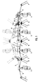
- die Rückansicht eines Kreiselzettwenders mit erfindungsgemäßen trennbaren Klauenkupplungen, wobei gestrichelt die hochgeschwenkte Nichtarbeitsstellung der äußeren Rahmenteile mit den daran befestigten Kreiseleinheiten mit eingezeichnet ist,
- Fig. 2
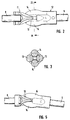
- eine vergrößerte Ansicht der in Eingriffstellung befindlichen Klauenkupplungsteile,
- Fig. 3
- einen Schnitt längs der Linie III-III in Fig. 2,
- Fig. 4
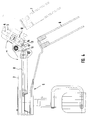
- eine vergrößerte Ansicht des Gelenkbereichs zwischen zwei Rahmenteilen in der Stellung, in der die Kupplungsteile gerade außer Eingriff gelangt sind,
- Fig. 5
- eine der Fig. 2 entsprechende vergrößerte Ansicht der Klauenkupplung, bei der das mögliche Winkelspiel der Rahmenteile gegeneinander eingezeichnet ist,
- Fig. 6
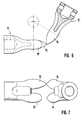
- eine vergrößerte Ansicht der Kupplung beim AufeinanderfahrenSpitze auf Spitze" der Mitnehmerkörper der Klauenkupplungsteile, und

- Fig. 7
- eine Draufsicht auf die Klauenkupplung entsprechend Fig. 6 von oben, wobei abweichend von der Anordnung nach Fig. 6 einer der Mitnehmerkörper des linken Klauenkupplungsteils kürzer ausgebildet ist als der andere.
- Fig. 1
- the rear view of a rotary tedder with separable claw clutches according to the invention, the broken-up non-working position of the outer frame parts with the attached rotary units is also shown,
- Fig. 2
- 3 shows an enlarged view of the claw coupling parts which are in the engaged position,
- Fig. 3
- 2 shows a section along the line III-III in FIG. 2,
- Fig. 4
- 3 shows an enlarged view of the joint area between two frame parts in the position in which the coupling parts have just come out of engagement,
- Fig. 5
- 2 corresponding enlarged view of the claw coupling, in which the possible angular play of the frame parts against each other is shown,
- Fig. 6
- an enlarged view of the clutch when moving together Tip to tip "the driver body of the claw coupling parts, and
- Fig. 7
- a top view of the claw coupling according to FIG. 6 from above, wherein, deviating from the arrangement according to FIG. 6, one of the driver bodies of the left claw coupling part is shorter than the other.
Der in Fig. 1 schematisch von hinten gezeigte Kreiselzettwender umfaßt einen Rahmen 1 mit zwei inneren Rahmenteilen 2 und zwei gelenkig daran angelenkten, nach oben in die gestrichelte Fahr- oder Nichtgebrauchstellung schwenkbaren äußeren Rahmenteilen 3, wobei an jedem der Rahmenteile 2 und 3 ein Laufrad 4 und eine Kreiseleinheit 5 mit in der Betriebsstellung nach Fig. 1 kämmend ineinander eingreifenden Zinkengruppen 6, 7 angeordnet ist. Von einem gemeinsamen nicht gezeichneten Antrieb in der Deichsel zum Zugfahrzeug werden die einzelnen Kreisel 5 durch Antriebswellen 8, 9 angetrieben, die im Bereich der Gelenke 10 zwischen den inneren und äußeren Rahmenteilen 2, 3 über trennbare gelenkige Klauenkupplungen miteinander verbunden sind.The rotary tedder shown schematically in FIG. 1 comprises a frame 1 with two
Die im wesentlichen gleich ausgebildeten Klauenkupplungsteile 11 und 12 umfassen dabei im dargestellten Ausführungsbeispiel jeweils zwei zur jeweiligen Antriebswelle 8, 9 parallele beabstandete spindelfömige Mitnehmerkörper 13 und 14, wobei gemäß einer bevorzugten in Fig. 7 dargestellten Ausführungsform einer der Mitnehmerkörper 13' kürzer ausgebildet ist als der andere Mintnehmerkörper 13, so daß beim Einkuppelvorgang, wie er in Fig. 6 gezeigt ist, bei einer Stellung nicht jeweils beide Spitzen der Mitnehmerkörper aneinanderstoßen können und sich dadurch die Kupplungshälften nicht gegenseitig am Eindrehen in die Kuppelposition behindern können.The essentially identical
In Fig. 5 ist angedeutet, daß die Form der spindelförmigen Mitnehmerkörper 13, 14 so gewählt ist, daß auch unter Berücksichtigung der im Betrieb möglichen Abwinklungen der Rahmenteile 2, 3 gegeneinander, was zu einer entsprechenden Abwinklung auch der Antriebswellen 8, 9 führt, die Mitnehmerkörper stets voll in Eingriff stehen und so eine Drehbewegung möglichst spielfrei übertragen können.In Fig. 5 it is indicated that the shape of the spindle-
Aus Fig. 4 erkennt man darüber hinaus, daß die Ausbildung so getroffen ist, daß der Schwenkwinkel α des äußeren Rahmenteils 3 gegenüber dem inneren Rahmenteil 2, bei welchem das Ein- bzw. Auskuppeln der Mitnehmerkörper 13, 14 stattfindet, kleiner ist als der Schwenkwinkel, ab dem die Zinken 6, 7 der an den Rahmenteilen 2 und 3 befestigten Kreiseleinheiten 5 ineinandergreifen. Dadurch ist sichergestellt, daß zunächst die Mitnehmerkörper 13, 13'; 14 der Klauenkupplungsteile 11, 12 sich beim Zusammenfahren in die um 180° gegeneinander verdrehte Position gemäß Fig. 3 gebracht haben und damit auch die zugehörigen Kreiseleinheiten 5 derart verdreht haben, daß ihre Zinken zum gegenseitigen Eingriff gegeneinander versetzt sind, so daß beim weiteren Herunterklappen des äußeren Rahmenteils 3 gegenüber dem inneren Rahmenteil 2 eine Blockierung der Kreiseleinheiten durch Aufeinanderfahren der Zinkenteile 6, 7 sicher verhindert ist.From Fig. 4 it can also be seen that the design is such that the pivot angle α of the
Claims (4)
Applications Claiming Priority (2)
| Application Number | Priority Date | Filing Date | Title |
|---|---|---|---|
| DE29609520U DE29609520U1 (en) | 1996-05-29 | 1996-05-29 | Separable articulated claw coupling |
| DE29609520U | 1996-05-29 |
Publications (2)
| Publication Number | Publication Date |
|---|---|
| EP0809927A1 true EP0809927A1 (en) | 1997-12-03 |
| EP0809927B1 EP0809927B1 (en) | 2001-02-14 |
Family
ID=8024517
Family Applications (1)
| Application Number | Title | Priority Date | Filing Date |
|---|---|---|---|
| EP97106978A Expired - Lifetime EP0809927B1 (en) | 1996-05-29 | 1997-04-26 | Separable articulated claw coupling |
Country Status (3)
| Country | Link |
|---|---|
| EP (1) | EP0809927B1 (en) |
| AT (1) | ATE199114T1 (en) |
| DE (2) | DE29609520U1 (en) |
Families Citing this family (2)
| Publication number | Priority date | Publication date | Assignee | Title |
|---|---|---|---|---|
| DE202009015958U1 (en) | 2009-11-23 | 2011-04-07 | Kverneland Asa | Rotary coupling and agricultural machine |
| US12181004B2 (en) | 2021-06-22 | 2024-12-31 | JSI Equipment Solutions LLC | Flexible coupling for a drive train |
Citations (5)
| Publication number | Priority date | Publication date | Assignee | Title |
|---|---|---|---|---|
| DE1507338A1 (en) * | 1966-11-19 | 1970-01-08 | Massey Ferguson Ind Ltd | Automatic shaft coupling |
| GB2004026A (en) * | 1977-09-10 | 1979-03-21 | Kloeckner Humboldt Deutz Ag | Coupling for a divided drive shaft |
| EP0296666A1 (en) * | 1987-06-23 | 1988-12-28 | C. van der Lely N.V. | A hay-making machine |
| EP0370933A1 (en) * | 1988-11-21 | 1990-05-30 | Kuhn S.A. | Agricultural machine, especially for hay-making, with a articulated frame |
| EP0772970A1 (en) * | 1995-11-07 | 1997-05-14 | Kuhn S.A. | Haymaking machine, especially a tedder |
-
1996
- 1996-05-29 DE DE29609520U patent/DE29609520U1/en not_active Expired - Lifetime
-
1997
- 1997-04-26 EP EP97106978A patent/EP0809927B1/en not_active Expired - Lifetime
- 1997-04-26 DE DE59702994T patent/DE59702994D1/en not_active Expired - Fee Related
- 1997-04-26 AT AT97106978T patent/ATE199114T1/en not_active IP Right Cessation
Patent Citations (5)
| Publication number | Priority date | Publication date | Assignee | Title |
|---|---|---|---|---|
| DE1507338A1 (en) * | 1966-11-19 | 1970-01-08 | Massey Ferguson Ind Ltd | Automatic shaft coupling |
| GB2004026A (en) * | 1977-09-10 | 1979-03-21 | Kloeckner Humboldt Deutz Ag | Coupling for a divided drive shaft |
| EP0296666A1 (en) * | 1987-06-23 | 1988-12-28 | C. van der Lely N.V. | A hay-making machine |
| EP0370933A1 (en) * | 1988-11-21 | 1990-05-30 | Kuhn S.A. | Agricultural machine, especially for hay-making, with a articulated frame |
| EP0772970A1 (en) * | 1995-11-07 | 1997-05-14 | Kuhn S.A. | Haymaking machine, especially a tedder |
Also Published As
| Publication number | Publication date |
|---|---|
| DE29609520U1 (en) | 1996-08-29 |
| ATE199114T1 (en) | 2001-02-15 |
| DE59702994D1 (en) | 2001-03-22 |
| EP0809927B1 (en) | 2001-02-14 |
Similar Documents
| Publication | Publication Date | Title |
|---|---|---|
| AT389974B (en) | CYLINDER HAY ADVERTISING MACHINE | |
| EP0277343B1 (en) | Mowing machine | |
| DE2426209B2 (en) | AGRICULTURAL MACHINE | |
| DE60320097T2 (en) | Hay-making machine | |
| DE60003614T2 (en) | TOWING MACHINE WITH AT LEAST ONE ROTOR FOR SWATHING WITH POSITION ADJUSTABLE PLATE | |
| DE2111227A1 (en) | Harvester | |
| DE2843782C2 (en) | Rotary haymaking machine for swathing or turning or for tedding/turning | |
| DE4340384B4 (en) | Hay-making machine | |
| EP0291812B1 (en) | Agricultural machine, especially a rotary tedder | |
| DE1232388B (en) | Haymaking machine | |
| AT379048B (en) | QUICK COUPLING FOR CONNECTING AGRICULTURAL WORKING MACHINES | |
| EP0809927B1 (en) | Separable articulated claw coupling | |
| EP2923541B1 (en) | Agricultural cultivation device | |
| EP0548720A2 (en) | Hay making machine | |
| DE69705337T2 (en) | Hay-making machine | |
| EP0270052B1 (en) | Hay-making machine | |
| DE29708799U1 (en) | Multi-rotor large swather | |
| DE2844235A1 (en) | HAY ADVERTISING MACHINE | |
| DE69304558T2 (en) | Haymaking machine with a frame provided with controlled support wheels | |
| DE602005005143T2 (en) | Hay-making machine | |
| DE69201581T2 (en) | Agricultural machine. | |
| DE10021660C2 (en) | Harvester, especially self-propelled forage harvesters | |
| DE69604317T2 (en) | Haymaking machine | |
| EP1665922A1 (en) | Haymaking machine | |
| DE69417689T2 (en) | Haymaking machine |
Legal Events
| Date | Code | Title | Description |
|---|---|---|---|
| PUAI | Public reference made under article 153(3) epc to a published international application that has entered the european phase |
Free format text: ORIGINAL CODE: 0009012 |
|
| AK | Designated contracting states |
Kind code of ref document: A1 Designated state(s): AT DE FR |
|
| 17P | Request for examination filed |
Effective date: 19980516 |
|
| 17Q | First examination report despatched |
Effective date: 19981014 |
|
| GRAG | Despatch of communication of intention to grant |
Free format text: ORIGINAL CODE: EPIDOS AGRA |
|
| GRAG | Despatch of communication of intention to grant |
Free format text: ORIGINAL CODE: EPIDOS AGRA |
|
| GRAH | Despatch of communication of intention to grant a patent |
Free format text: ORIGINAL CODE: EPIDOS IGRA |
|
| GRAH | Despatch of communication of intention to grant a patent |
Free format text: ORIGINAL CODE: EPIDOS IGRA |
|
| GRAA | (expected) grant |
Free format text: ORIGINAL CODE: 0009210 |
|
| AK | Designated contracting states |
Kind code of ref document: B1 Designated state(s): AT DE FR |
|
| REF | Corresponds to: |
Ref document number: 199114 Country of ref document: AT Date of ref document: 20010215 Kind code of ref document: T |
|
| ET | Fr: translation filed | ||
| REF | Corresponds to: |
Ref document number: 59702994 Country of ref document: DE Date of ref document: 20010322 |
|
| PLBE | No opposition filed within time limit |
Free format text: ORIGINAL CODE: 0009261 |
|
| STAA | Information on the status of an ep patent application or granted ep patent |
Free format text: STATUS: NO OPPOSITION FILED WITHIN TIME LIMIT |
|
| 26N | No opposition filed | ||
| PGFP | Annual fee paid to national office [announced via postgrant information from national office to epo] |
Ref country code: FR Payment date: 20030401 Year of fee payment: 7 |
|
| PGFP | Annual fee paid to national office [announced via postgrant information from national office to epo] |
Ref country code: AT Payment date: 20030424 Year of fee payment: 7 |
|
| PGFP | Annual fee paid to national office [announced via postgrant information from national office to epo] |
Ref country code: DE Payment date: 20030428 Year of fee payment: 7 |
|
| PG25 | Lapsed in a contracting state [announced via postgrant information from national office to epo] |
Ref country code: AT Free format text: LAPSE BECAUSE OF NON-PAYMENT OF DUE FEES Effective date: 20040426 |
|
| PG25 | Lapsed in a contracting state [announced via postgrant information from national office to epo] |
Ref country code: DE Free format text: LAPSE BECAUSE OF NON-PAYMENT OF DUE FEES Effective date: 20041103 |
|
| PG25 | Lapsed in a contracting state [announced via postgrant information from national office to epo] |
Ref country code: FR Free format text: LAPSE BECAUSE OF NON-PAYMENT OF DUE FEES Effective date: 20041231 |
|
| REG | Reference to a national code |
Ref country code: FR Ref legal event code: ST |