EP0809910B1 - Channel identification - Google Patents
Channel identification Download PDFInfo
- Publication number
- EP0809910B1 EP0809910B1 EP96937462A EP96937462A EP0809910B1 EP 0809910 B1 EP0809910 B1 EP 0809910B1 EP 96937462 A EP96937462 A EP 96937462A EP 96937462 A EP96937462 A EP 96937462A EP 0809910 B1 EP0809910 B1 EP 0809910B1
- Authority
- EP
- European Patent Office
- Prior art keywords
- channel
- test signal
- signal
- impulse response
- values
- Prior art date
- Legal status (The legal status is an assumption and is not a legal conclusion. Google has not performed a legal analysis and makes no representation as to the accuracy of the status listed.)
- Expired - Lifetime
Links
- 108091006146 Channels Proteins 0.000 claims description 165
- 230000004044 response Effects 0.000 claims description 101
- 238000000034 method Methods 0.000 claims description 41
- 238000012360 testing method Methods 0.000 claims description 41
- 238000004891 communication Methods 0.000 claims description 33
- 239000011159 matrix material Substances 0.000 claims description 19
- 238000000354 decomposition reaction Methods 0.000 claims description 3
- 238000001914 filtration Methods 0.000 claims 3
- 238000002592 echocardiography Methods 0.000 description 13
- 239000013598 vector Substances 0.000 description 6
- 238000001228 spectrum Methods 0.000 description 5
- 230000005540 biological transmission Effects 0.000 description 4
- 238000002474 experimental method Methods 0.000 description 4
- 238000012545 processing Methods 0.000 description 4
- 238000005070 sampling Methods 0.000 description 4
- 101100379079 Emericella variicolor andA gene Proteins 0.000 description 3
- 239000000654 additive Substances 0.000 description 3
- 230000000996 additive effect Effects 0.000 description 3
- 230000008901 benefit Effects 0.000 description 3
- 230000008859 change Effects 0.000 description 3
- 238000012512 characterization method Methods 0.000 description 3
- 238000010586 diagram Methods 0.000 description 3
- 230000000694 effects Effects 0.000 description 3
- 230000003044 adaptive effect Effects 0.000 description 2
- 238000013459 approach Methods 0.000 description 2
- 230000006399 behavior Effects 0.000 description 2
- 238000005352 clarification Methods 0.000 description 2
- 230000008054 signal transmission Effects 0.000 description 2
- 238000012935 Averaging Methods 0.000 description 1
- 230000004075 alteration Effects 0.000 description 1
- 230000002238 attenuated effect Effects 0.000 description 1
- 230000001364 causal effect Effects 0.000 description 1
- 230000001419 dependent effect Effects 0.000 description 1
- 238000013461 design Methods 0.000 description 1
- 238000009472 formulation Methods 0.000 description 1
- 230000006870 function Effects 0.000 description 1
- 230000014509 gene expression Effects 0.000 description 1
- 239000000203 mixture Substances 0.000 description 1
- 230000008569 process Effects 0.000 description 1
- 230000035945 sensitivity Effects 0.000 description 1
Images


Classifications
-
- H—ELECTRICITY
- H04—ELECTRIC COMMUNICATION TECHNIQUE
- H04N—PICTORIAL COMMUNICATION, e.g. TELEVISION
- H04N5/00—Details of television systems
- H04N5/14—Picture signal circuitry for video frequency region
- H04N5/21—Circuitry for suppressing or minimising disturbance, e.g. moiré or halo
-
- H—ELECTRICITY
- H04—ELECTRIC COMMUNICATION TECHNIQUE
- H04L—TRANSMISSION OF DIGITAL INFORMATION, e.g. TELEGRAPHIC COMMUNICATION
- H04L25/00—Baseband systems
- H04L25/02—Details ; arrangements for supplying electrical power along data transmission lines
- H04L25/0202—Channel estimation
- H04L25/024—Channel estimation channel estimation algorithms
- H04L25/0242—Channel estimation channel estimation algorithms using matrix methods
-
- H—ELECTRICITY
- H04—ELECTRIC COMMUNICATION TECHNIQUE
- H04L—TRANSMISSION OF DIGITAL INFORMATION, e.g. TELEGRAPHIC COMMUNICATION
- H04L25/00—Baseband systems
- H04L25/02—Details ; arrangements for supplying electrical power along data transmission lines
- H04L25/0202—Channel estimation
- H04L25/0212—Channel estimation of impulse response
-
- H—ELECTRICITY
- H04—ELECTRIC COMMUNICATION TECHNIQUE
- H04L—TRANSMISSION OF DIGITAL INFORMATION, e.g. TELEGRAPHIC COMMUNICATION
- H04L25/00—Baseband systems
- H04L25/02—Details ; arrangements for supplying electrical power along data transmission lines
- H04L25/0202—Channel estimation
- H04L25/0224—Channel estimation using sounding signals
- H04L25/0228—Channel estimation using sounding signals with direct estimation from sounding signals
-
- H—ELECTRICITY
- H04—ELECTRIC COMMUNICATION TECHNIQUE
- H04N—PICTORIAL COMMUNICATION, e.g. TELEVISION
- H04N5/00—Details of television systems
- H04N5/14—Picture signal circuitry for video frequency region
- H04N5/21—Circuitry for suppressing or minimising disturbance, e.g. moiré or halo
- H04N5/211—Ghost signal cancellation
Definitions
- This invention generally relates to a method and apparatus for identifying the characteristics of a communication channel, and more particularly, to a method and apparatus for substantially cancelling echoes (also referred to as "ghosts") which can occur during the transmission of television signals.
- Signal restoration often can be achieved if the communication channel is fully characterized, at least as to those parameters which contribute to the signal alteration.
- a frequently essential component of the signal restoration problem is that of identifying the characteristics of the communication channel.
- Characterization of a channel by its channel impulse response plays a vital role in ghost-cancellation, equalization, and adaptive filter design.
- channel impulse response data are used to develop finite-impulse response (FIR) and infinite-impulse response (IIR) filters to cancel echoes, such as taught for example in U.S. Pat. Nos. US-A-5,047,859 (Attorney's docket PHA 21.622) and US-A-5,111,298 (Attorney's docket PHA 21.664). It is essential that an estimation error in the channel impulse response be as small as possible to improve overall performance, which may be referred to in terms of both initial acquisition and steady-state tracking.
- DE-A-40.28.322 discloses a method of improving a channel parameter estimation in which the noise-affected input signal is separated by means of an additional device into an object magnitude, and subsequently subjected to a postfiltering.
- the additional device the input signal is observed during a time period of sufficient length, whereafter provisional estimations are made.
- the additional device is preferably a minimum least square error estimator.
- a straight forward approach to the channel identification problem is to transmit a known signal over a desired channel, and to receive the transmitted signal after it has passed through the channel.
- the known signal however is corrupted by the linear channel and noise.
- the noise is assumed to be additive white Gaussian noise (AWGN).
- AWGN additive white Gaussian noise
- the originally transmitted signal is then compared with the received signal, and a model of the channel characteristics is developed based on the comparison.
- the known signal can also be sent repetitively so that simple averaging techniques can be used to increase the signal-to-noise ratio (SNR) and, perhaps, as an approximation, it can be assumed that the noise is negligible. Characterization of the channel is then possible for the bandwidth of the known transmission signal.
- SNR signal-to-noise ratio
- a ghost-cancellation-reference (GCR) signal used for analog NTSC ghost-cancellation has a bandwidth of 4.2 MHz.
- GCR ghost-cancellation-reference
- A/D analog-to-digital converter used in known receivers for implementing low-cost digital signal processing techniques has a sampling rate of 14.3 MHz, thus effectively considering a channel of 7.15 MHz; wherein the bandwidth of the channel is determined by filters which precede the A/D converter in the receiver.
- the GCR signal has a finite non-zero length which implies that the signal is not strictly bandlimited; actually a small amount of energy is also present between the range 4.2 to 7.15 MHz.
- the part of the GCR signal between the range 4.2 to 7.15 MHz becomes extremely unreliable thereby causing inaccuracies in known channel-impulse response estimation methods.
- An object of the present invention is to overcome the problems in the art as discussed above. Another object of the present invention is to provide a method and apparatus for channel identification which provides an estimation of the channel over the entire frequency band thereof even though information is only reliable over part of the band.
- the invention provides a communication channel identification, a channel induced distortion removal, and a television receiver as defined by the independent claims.
- the dependent claims define advantageous embodiments.
- a TV ghost-cancellation system has been chosen to demonstrate the power and effectiveness of the present invention. Accordingly, a ghost-cancellation channel model has been described herein.
- the channel identification method is formulated using LS techniques, according to the present invention and as further described herein below. Furthermore, as will become apparent from the following, experimental results obtained when using the LS estimators in accordance with the present invention provide near-optimal channel identification.
- the present invention takes into account the following aspects. If the maximum length of the impulse response of the channel is known, then it is possible to develop a channel identification technique which effectively performs an interpolation of the 'reliable' frequency response, obtained using less noisy information, to determine the total channel frequency response. For example, it is known that over a CATV channel, the impulse response length is at most 2 ⁇ sec. Also, if the ratio of the impulse-response length to the observation time window (e.g., the interval N+L relating to the sequence of values of the signal y, as defined in Eq. 2, below) is smaller than the ratio of the 'reliable' information band to the total bandwidth, then the interpolation method according to the present invention can be very accurate.
- the ratio of the impulse-response length to the observation time window e.g., the interval N+L relating to the sequence of values of the signal y, as defined in Eq. 2, below
- the method and apparatus for channel identification in accordance with the present invention incorporates a method based on known least-squares (LS) linear prediction theory, further using known singular-value-decomposition (SVD) techniques. Also, if information about noise characteristics is independently determined, then the problem of interpolation can be reformulated as a generalized LS prediction problem.
- LS least-squares
- SSD singular-value-decomposition
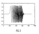
- a GCR signal as shown in FIG. 2, known in the art as the Koo GCR is used, the GCR having properties as described above.
- This GCR signal is inserted during line 19 in the vertical blanking interval of a transmitted television signal.
- perfect NTSC timing synch is assumed. This implies that digital signal processing can be used to implement the ghost-cancellation filter.
- the A/D converter uses a sampling frequency of 14.3 MHz, which is four times the color sub-carrier frequency. Assuming that the channel does not change very rapidly, multiple copies of the corrupted GCR signal are averaged to minimize noise.
- the channel identification problem is to determine the impulse response of the channel.
- FIG. 1A an illustration of the actual TV channel signal transmission path is shown. Since perfect timing is assumed, the TV channel can be modeled as a general discrete-time channel, as illustrated in FIG. 1B.
- the method and apparatus in accordance with the present invention are thus not specific to the ghost-cancellation strategy, but can be generalized to any channel modeled as shown in FIG. 1B, with subsequent assumptions.
- samples of the received signal are represented by y n ⁇ y ( nT ), where T is the sampling interval.
- h n representing a sampled discrete channel, is assumed to be nonzero for a finite number of indices in an interval defined by - L(t), M(t), (i.e., the interval [-LT, MT ], or equivalently, in the interval [-L, M ])
- T is the sampling interval of the A/D converter 14
- p min ( n , M )
- w n is a noise component, and where it is also assumed that x n is causal.
- h ( M + L ) ⁇ 1 ( h - L , h - L +1 ,..., h M -1 ) T
- y ( N + L ) ⁇ 1 ( y - L , y - L +1 ,..., y N -1 ) T
- w ( N+L )x1 The problem of channel identification is then to find an estimate, h and , such that the p -th norm of the error in estimation, ⁇ h - h and ⁇ p is minimized.
- the sequence x n is bandlimited to a fraction of the (- ⁇ , ⁇ ) band.
- x n has finite support, then the energy in the band outside the bandwidth occupied by x n would be very small, but not zero. This implies that information about the channel outside this band would be corrupted by noise. The effects of this can be removed by some simple non-linear processing techniques, as will be described below.
- noise is zero, that is, when noise is absent.
- any perturbations in the matrix representation is measured by a bound on the normalized error defined as the norm of the error, ⁇ h - h and ⁇ , divided by ⁇ h ⁇ .
- the normalized error is proportional to ⁇ ( T ) 2 .
- the LS estimators h and A and h and B can be shown to also be the best linear unbiased estimates as determined based upon known adaptive filter theory. If w is also Gaussian, then the LS estimates achieve the Cramer-Rao lower bound for unbiased estimators. Thus LS estimators, h and A and h and B , are optimal for 'white' Gaussian noise.
- estimator h and B is relatively insensitive to the variance of the additive noise. Since ⁇ ( h and A ) i corresponds to the noise variance, note that for large values of ⁇ 2 , estimator h and B may be a better estimator compared to h and A . This is observed in the experiments described subsequently herein.
- the channel identification problem in ghost-cancellation was considered.
- the matrix T was generated using the Koo GCR signal shown in FIG. 2 (amplitude on the vertical axis, samples on the horizontal axis). Every sample in FIG. 2 represents a time interval of 1/14.3 ⁇ sec. Furthermore, the GCR signal has a 3 dB bandwidth of 4.15 MHz.
- the GCR signal was passed through a multipath channel and the results of the first and second estimators, h and A and h and B , given by (EQ 4) and (EQ 9), respectively, were studied in different scenarios. Additionally, the error was defined to be the squared-estimation error (SE), ⁇ h - h and ⁇ 2 , in dB scale.
- SE squared-estimation error
- FIG. 3 the impulse response obtained using the first estimator h and A in the presence of no noise and with M + L equal to 24 is shown.
- the estimated channel impulse response is shown by the solid line 20. Also shown with 'square' symbols 22 are the expected impulse-response values.
- the estimator provides discrete values (i.e., points on the graph) and that the solid line 20 has been drawn for clarification purposes to demonstrate the results of the estimator as compared to the actual expected impulse response values.
- the estimated channel impulse response corresponds to values of h n at different times, further corresponding to respective sample numbers.
- FIG. 3 is thus a graph of a sequence of coefficients derived using the first estimator h and A .
- pre-echoes 19 there are two pre-echoes identified by reference numeral 19 in the multipath response, wherein the pre-echoes make characterization of the channel more difficult.
- post-echoes also occurred in the estimated channel impulse response, as indicated by the reference numeral 23.
- the correspondence between the estimated and expected impulse-response is very close; the measured SE was found to be -58.1 dB.
- FIG. 4 there is shown the corresponding frequency response of the impulse response of FIG.3.
- the estimated channel frequency response is shown by the solid line 30.
- the 'x' symbols 32 in FIG. 4 specify the expected magnitude of the frequency response computed from the known channel impulse response.
- FIG. 4 also shows the magnitude of the frequency-response of an idealized GCR, as shown by the dotted line 34.
- part of the spectrum comprises reliable information (as identified by reference numeral 36 in two places) and part of the spectrum comprises unreliable information (as identified by reference numeral 38).
- the region of the GCR signal identified by reference numeral 38 contains an extremely low energy (i.e., is non-zero) and is considered unreliable.
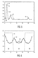
- FIGs. 5 and 6 show the impulse response and the magnitude of the frequency response for the second estimator, h and B , for M + L equal to 24. Since sensitivity of this second estimator to numerical precision is higher, some small singular values of T T T were set to zero (all experiments were carried out using single-precision floating point calculations). As a result, the impulse response (sample value against sample number) is slightly degraded as shown in FIG. 5, wherein the estimated channel impulse response is shown by the solid line 40. With respect to FIG. 5, it is noted that the estimator provides discrete values (i.e., points on the graph) and that the solid line 40 has been drawn for clarification purposes to demonstrate the results of the estimator as compared to the actual expected impulse response values. FIG.
- FIG. 5 is thus a graph of a sequence of coefficients derived using the second estimator h and B . It is noted that there are two pre-echoes identified by reference numeral 39 in the multipath response. The main coefficient of the estimated channel impulse response, corresponding to h n equal to h 0 , is identified by the reference numeral 41. In addition, post-echoes also occurred in the estimated channel impulse response, as indicated by the reference numeral 43. Referring still to FIG. 5, note also that a slight wiggle occurs in solid line 40 between the range of sample numbers from 6 to 19, which is indicative that the estimator is different from zero.
- FIG. 6 The corresponding estimated channel frequency response (magnitude of the frequency response against frequency) of the impulse response of FIG. 5 is shown in FIG. 6, illustrated by the solid line 50.
- the dashed line joining the 'x' symbols 52 specify the expected magnitude of the frequency response computed from the known channel impulse response.
- FIG. 6 also shows the magnitude of the frequency-response of the idealized GCR as shown by the dotted line 54. It is interesting to note that the singular values that were truncated to zero caused errors in the frequency response in the region where the GCR energy is very small, as can be seen from FIG. 6, between 7.4 and 16.6 frequency units, corresponding to the unreliable information region identified by reference numeral 38. In other words, the estimated response does not equal the expected response; rather, the estimated response deviates slightly from the expected response.
- the inverse could be calculated by using the singular values of T and (EQ 10). For both cases, the results showed that four singular values need to be truncated to obtain the minimum SE.
- M + L is known (or upperbounded)
- such a technique as described herein can be used to determine an optimal number of truncated values. If, instead, M + L is made variable at the receiver, then the number of such truncated values can be obtained with less complexity by alternate non-linear least squares techniques known in the art.
- M + L One way to avoid choosing different values of M + L is by using a conservative upper-bound to the channel impulse response. It is then of interest to determine if the LS estimators are sensitive to the choice of M + L . Accordingly, for the same multipath channel, the value of M + L was changed and the SE calculated for the two estimators, h and A and h and B as outlined in Table 2. For the second estimator, h and B , described by (EQ 9), all singular values less than 1e-4 were set to zero.
- the first estimator, h and A tries to use information present in all the singular values, or in other words, the information present in the entire digital spectrum of the GCR signal.
- the signal is attenuated enormously in the range of 4.2 to 7.15 MHz (corresponding to the range of approximately 7.4 to 16.6 as shown in FIG. 4 and as expressed in units of normalized frequency) and noise in this region degrades the performance for low SNR.
- a prescribed number of singular values i.e., the smaller singular values
- which corresponds to information in the region of 4.2 to 7.15 MHz are truncated, which corresponds to ignoring information in this region, then improved performance is obtained.
- the first estimator thus advantageously provides an estimation of the channel impulse response over the entire frequency band in light of the fact that less than the entire digital spectrum of the GCR signal is available, i.e., information is incomplete or unreliable over part of the spectrum.
- the second estimator, h and B is more robust to the influence of noise since the smaller singular values have been made much smaller and are ignored. Note that this later result with respect to the second estimator was expected based on the discussion provided herein above at the end of section A and the beginning of section B.
- the multipath channel was chosen to be the same for comparison purposes. Similar behavior was obtained for a variety of different multipath channels.
- FIG. 7 further illustrates a general ghost-cancellation system as will be described further herein below.
- the two matrix multiplications of (EQ 9), for determining estimator h and B can be implemented in software in digital-signal processor (DSP) 9 using standard software library routines.
- DSP digital-signal processor
- suitable algorithms for multiplication of a symmetric matrix with a vector may also be used. Note that (M+L)*(M+L-1)/2 values are zero in T , which simplifies the implementation of the multiplication of the Toeplitz matrix T with the received signal vector.
- the characteristics of the communication channel (which include the echo artifacts, if any) are determined at the receiver in accordance with the method and apparatus of the present invention, corresponding to estimators h and A and h and B . From these characteristics, an inverse channel characteristic is determined in the form of a sequence of filter coefficients. These coefficients are then provided to filters which are used to implement the inverse channel processing, i.e., the echo cancellation.
- a received video signal contains echoes which are comprised of superimposed copies of the originally transmitted signal, which have different delay times and amplitudes.
- the strongest signal component represents the originally transmitted or main signal component. Looking in the time domain, any echo component occurring before the main signal component is called a "pre-echo” and any copy occurring after the main signal component is called a "post-echo”.
- FIG. 7 describes an echo cancellation circuit which can be used to cancel both types of echoes.
- An IIR filter 61 is used to cancel post-echoes and an FIR filter 63 is used to cancel pre-echoes.
- Video samples are received and input to an analog-to-digital (A/D) converter 65 and a test signal commonly known as the ghost cancellation reference (GCR) signal which is transmitted during the vertical blanking interval of a television signal, is separated and fed to a buffer memory 67.
- GCR ghost cancellation reference
- This reference signal which has been distorted according to the channel characteristics, is sometimes sampled over a number of frames, and an average of the sampled versions is then fed to processor 69 which is shown in more detail in FIG. 8.
- Read-Only Memory (ROM) 70 contains a preprocessed and stored version of the GCR as transmitted, and the contents of buffer 67 are compared to the stored version of the GCR from ROM 70 in CPU 72 and from this comparison, the impulse response of the channel can be determined using the estimators, h and A and h and B , in accordance with the present invention, and further for computing a sequence of coefficients for the filters 61 and 63.
- the Koo GCR signal was used, as shown in the time domain in FIG. 2.
- This GCR is the signal as transmitted and stored in ROM 70 and/or a processed version of which is stored in ROM 70. While the invention has been described with reference to using the Koo GCR signal, it is to be understood that the instant invention can be practised with any other type of test reference signal which eventually might be chosen as a standard.
- the filter coefficients are fed to the filters 61 and 63, the complete television signal is processed through these filters where the echo components are substantially reduced.
- the output of the IIR filter 61 is then fed to a digital-to-analog converter (D/A) 74 and thereafter presented as a video output signal.
- D/A digital-to-analog converter
- the second estimator, h and B demonstrated the effects of numerical precision in the situation when noise was absent (i.e., without truncating the singular values of less than le-4 as shown in Table 1), thus causing the SE performance to be inferior in the absence of noise.
- the SE performance of the second estimator, h and B is better in the presence of noise.
- the second estimator, h and B furthermore, has an added advantage of easier real-time implementation, especially in the case when the impulse-response span M + L is much smaller than the GCR signal span.
- the second estimator, h and B can thus be effectively used for channel identification as part of TV ghost-cancellation.
- preferred aspects of the invention provide a method and apparatus for channel identification utilizing two Least-Squares (LS) estimators.
- Each LS estimator is used for calculating a sequence of channel values, further for determining an estimated channel impulse response, over an entire frequency band thereof in light of the fact that information is incomplete or unreliable over part of the frequency band.
- Each LS estimator operates for the case when the estimated channel impulse response span is less than the span of a known test signal, the test signal having been transmitted over the channel for use in identifying the channel.
- each LS estimator is used to compute channel impulse response coefficients, wherein the system includes ghost-cancellation filters responsive to the channel impulse response for removing the effects of the channel from the signals.
Landscapes
- Engineering & Computer Science (AREA)
- Signal Processing (AREA)
- Power Engineering (AREA)
- Computer Networks & Wireless Communication (AREA)
- Multimedia (AREA)
- Physics & Mathematics (AREA)
- Mathematical Physics (AREA)
- Picture Signal Circuits (AREA)
- Cable Transmission Systems, Equalization Of Radio And Reduction Of Echo (AREA)
Applications Claiming Priority (3)
| Application Number | Priority Date | Filing Date | Title |
|---|---|---|---|
| US573857 | 1995-12-18 | ||
| US08/573,857 US5761088A (en) | 1995-12-18 | 1995-12-18 | Method and apparatus for channel identification using incomplete or noisy information |
| PCT/IB1996/001295 WO1997023089A1 (en) | 1995-12-18 | 1996-11-25 | Channel identification |
Publications (2)
| Publication Number | Publication Date |
|---|---|
| EP0809910A1 EP0809910A1 (en) | 1997-12-03 |
| EP0809910B1 true EP0809910B1 (en) | 2001-09-05 |
Family
ID=24293680
Family Applications (1)
| Application Number | Title | Priority Date | Filing Date |
|---|---|---|---|
| EP96937462A Expired - Lifetime EP0809910B1 (en) | 1995-12-18 | 1996-11-25 | Channel identification |
Country Status (6)
| Country | Link |
|---|---|
| US (1) | US5761088A (enExample) |
| EP (1) | EP0809910B1 (enExample) |
| JP (1) | JPH11501186A (enExample) |
| KR (1) | KR19980702348A (enExample) |
| DE (1) | DE69615005T2 (enExample) |
| WO (1) | WO1997023089A1 (enExample) |
Families Citing this family (34)
| Publication number | Priority date | Publication date | Assignee | Title |
|---|---|---|---|---|
| US5179444A (en) * | 1990-10-09 | 1993-01-12 | North American Philips Corporation | System for echo cancellation comprising an improved ghost cancellation reference signal |
| FR2762167B1 (fr) * | 1997-04-14 | 1999-09-24 | Nortel Matra Cellular | Sondage a ponderation spatiale d'une voie de transmission |
| US5914982A (en) * | 1997-06-13 | 1999-06-22 | Rockwell Semiconductor Systems, Inc. | Method and apparatus for training linear equalizers in a PCM modem |
| WO2000005847A1 (en) * | 1998-07-21 | 2000-02-03 | Nokia Networks Oy | Channel impulse response estimation using received signal variance |
| US6304299B1 (en) * | 1998-11-30 | 2001-10-16 | General Electric Company | System and method for mitigating multipath effects in television systems |
| US6141393A (en) * | 1999-03-03 | 2000-10-31 | Motorola, Inc. | Method and device for channel estimation, equalization, and interference suppression |
| US6470047B1 (en) * | 2001-02-20 | 2002-10-22 | Comsys Communications Signal Processing Ltd. | Apparatus for and method of reducing interference in a communications receiver |
| US6987797B2 (en) * | 2002-07-26 | 2006-01-17 | Qualcomm Incorporated | Non-parametric matched filter receiver for wireless communication systems |
| US7602851B2 (en) * | 2003-07-18 | 2009-10-13 | Microsoft Corporation | Intelligent differential quantization of video coding |
| US7580584B2 (en) * | 2003-07-18 | 2009-08-25 | Microsoft Corporation | Adaptive multiple quantization |
| US7738554B2 (en) | 2003-07-18 | 2010-06-15 | Microsoft Corporation | DC coefficient signaling at small quantization step sizes |
| US10554985B2 (en) | 2003-07-18 | 2020-02-04 | Microsoft Technology Licensing, Llc | DC coefficient signaling at small quantization step sizes |
| US8218624B2 (en) * | 2003-07-18 | 2012-07-10 | Microsoft Corporation | Fractional quantization step sizes for high bit rates |
| US7801383B2 (en) * | 2004-05-15 | 2010-09-21 | Microsoft Corporation | Embedded scalar quantizers with arbitrary dead-zone ratios |
| US7388935B2 (en) * | 2004-06-15 | 2008-06-17 | Telefonktiebolaget Lm Ericsson (Publ) | Method of inverting nearly Toeplitz or block Toeplitz matrices |
| US8422546B2 (en) | 2005-05-25 | 2013-04-16 | Microsoft Corporation | Adaptive video encoding using a perceptual model |
| US7974340B2 (en) | 2006-04-07 | 2011-07-05 | Microsoft Corporation | Adaptive B-picture quantization control |
| US8130828B2 (en) | 2006-04-07 | 2012-03-06 | Microsoft Corporation | Adjusting quantization to preserve non-zero AC coefficients |
| US7995649B2 (en) | 2006-04-07 | 2011-08-09 | Microsoft Corporation | Quantization adjustment based on texture level |
| US8503536B2 (en) | 2006-04-07 | 2013-08-06 | Microsoft Corporation | Quantization adjustments for DC shift artifacts |
| US8059721B2 (en) | 2006-04-07 | 2011-11-15 | Microsoft Corporation | Estimating sample-domain distortion in the transform domain with rounding compensation |
| US8711925B2 (en) | 2006-05-05 | 2014-04-29 | Microsoft Corporation | Flexible quantization |
| US8238424B2 (en) | 2007-02-09 | 2012-08-07 | Microsoft Corporation | Complexity-based adaptive preprocessing for multiple-pass video compression |
| US8498335B2 (en) | 2007-03-26 | 2013-07-30 | Microsoft Corporation | Adaptive deadzone size adjustment in quantization |
| US8243797B2 (en) | 2007-03-30 | 2012-08-14 | Microsoft Corporation | Regions of interest for quality adjustments |
| US8442337B2 (en) | 2007-04-18 | 2013-05-14 | Microsoft Corporation | Encoding adjustments for animation content |
| WO2008151137A2 (en) * | 2007-06-01 | 2008-12-11 | The Trustees Of Columbia University In The City Of New York | Real-time time encoding and decoding machines |
| US8331438B2 (en) | 2007-06-05 | 2012-12-11 | Microsoft Corporation | Adaptive selection of picture-level quantization parameters for predicted video pictures |
| WO2009006405A1 (en) | 2007-06-28 | 2009-01-08 | The Trustees Of Columbia University In The City Of New York | Multi-input multi-output time encoding and decoding machines |
| FI20085161A0 (fi) * | 2008-02-22 | 2008-02-22 | Nokia Corp | Signaalin käsittely elektronisessa laitteessa |
| US8189933B2 (en) | 2008-03-31 | 2012-05-29 | Microsoft Corporation | Classifying and controlling encoding quality for textured, dark smooth and smooth video content |
| US8897359B2 (en) | 2008-06-03 | 2014-11-25 | Microsoft Corporation | Adaptive quantization for enhancement layer video coding |
| WO2012109407A1 (en) | 2011-02-09 | 2012-08-16 | The Trustees Of Columbia University In The City Of New York | Encoding and decoding machine with recurrent neural networks |
| US8644265B2 (en) * | 2011-09-30 | 2014-02-04 | Xiao-an Wang | Wideband analog channel information feedback |
Citations (1)
| Publication number | Priority date | Publication date | Assignee | Title |
|---|---|---|---|---|
| DE4028322A1 (de) * | 1990-09-06 | 1992-03-19 | Bosch Gmbh Robert | Verfahren zur verbesserung einer kanalparameterschaetzung und anordnung zu dessen durchfuehrung |
Family Cites Families (8)
| Publication number | Priority date | Publication date | Assignee | Title |
|---|---|---|---|---|
| JP2534737B2 (ja) * | 1987-11-24 | 1996-09-18 | 日本電気ホームエレクトロニクス株式会社 | ゴ―スト除去用フィルタ回路 |
| EP0421526B1 (en) * | 1989-10-06 | 1996-07-31 | Koninklijke Philips Electronics N.V. | Adaptive ghost cancellation circuit |
| US5121211A (en) | 1990-10-09 | 1992-06-09 | North American Philips Corporation | System for echo cancellation comprising an improved ghost cancellation reference signal |
| US5047859A (en) * | 1990-10-09 | 1991-09-10 | North American Philips Corporation | Method and apparatus for communication channel identification and signal restoration |
| US5172232A (en) * | 1990-10-09 | 1992-12-15 | North American Philips Corporation | Method and apparatus for communication channel identification and signal restoration |
| US5111298A (en) * | 1990-10-09 | 1992-05-05 | North American Philips Corporation | Method and apparatus for communication channel identification and signal restoration |
| US5179444A (en) * | 1990-10-09 | 1993-01-12 | North American Philips Corporation | System for echo cancellation comprising an improved ghost cancellation reference signal |
| JP3351855B2 (ja) * | 1993-05-31 | 2002-12-03 | 株式会社日立国際電気 | 符号化伝送装置 |
-
1995
- 1995-12-18 US US08/573,857 patent/US5761088A/en not_active Expired - Fee Related
-
1996
- 1996-11-25 JP JP9522613A patent/JPH11501186A/ja not_active Abandoned
- 1996-11-25 WO PCT/IB1996/001295 patent/WO1997023089A1/en not_active Ceased
- 1996-11-25 KR KR1019970705745A patent/KR19980702348A/ko not_active Abandoned
- 1996-11-25 DE DE69615005T patent/DE69615005T2/de not_active Expired - Fee Related
- 1996-11-25 EP EP96937462A patent/EP0809910B1/en not_active Expired - Lifetime
Patent Citations (1)
| Publication number | Priority date | Publication date | Assignee | Title |
|---|---|---|---|---|
| DE4028322A1 (de) * | 1990-09-06 | 1992-03-19 | Bosch Gmbh Robert | Verfahren zur verbesserung einer kanalparameterschaetzung und anordnung zu dessen durchfuehrung |
Also Published As
| Publication number | Publication date |
|---|---|
| US5761088A (en) | 1998-06-02 |
| DE69615005D1 (de) | 2001-10-11 |
| DE69615005T2 (de) | 2002-06-13 |
| JPH11501186A (ja) | 1999-01-26 |
| KR19980702348A (ko) | 1998-07-15 |
| WO1997023089A1 (en) | 1997-06-26 |
| EP0809910A1 (en) | 1997-12-03 |
Similar Documents
| Publication | Publication Date | Title |
|---|---|---|
| EP0809910B1 (en) | Channel identification | |
| EP0463781B1 (en) | Ghost cancellation technique for analog TV | |
| US5361102A (en) | System to cancel ghosts in NTSC television transmission | |
| US5121211A (en) | System for echo cancellation comprising an improved ghost cancellation reference signal | |
| US5659583A (en) | Tone canceller for QAM demodulator | |
| US20040071241A1 (en) | Multipath signal strength indicator | |
| US5568202A (en) | System for echo cancellation comprising an improved ghost cancellation reference signal | |
| KR20040101213A (ko) | 텔레비젼 수신기 및 라인/프레임 패턴과 동시에 샘플스트림을 처리하는 방법 | |
| US5111298A (en) | Method and apparatus for communication channel identification and signal restoration | |
| US6269131B1 (en) | Physical channel estimator | |
| JPH07322097A (ja) | 映像信号処理装置のゴースト除去回路を駆動するための方法 | |
| EP0561556B1 (en) | Video signal equalizer | |
| US5172232A (en) | Method and apparatus for communication channel identification and signal restoration | |
| JP2538963B2 (ja) | 波形等化装置 | |
| Case et al. | Measurement of multi-path effects in video signals | |
| US5280355A (en) | Television deghosting apparatus using pseudorandom sequence detector | |
| KR100292476B1 (ko) | 티브이의 고스트 제거 오차 저감 회로 및 그 방법 | |
| US6462787B1 (en) | Digital ghost cancellation using teletext data lines | |
| KR0139191B1 (ko) | 고스트제거장치 | |
| JP3430087B2 (ja) | ゴースト除去装置 | |
| KR970008094B1 (ko) | 고스트 제거기에서의 입력 신호 연산 방법 | |
| KR100283888B1 (ko) | 고스트 제거 장치의 필터 계수 산출 방법 | |
| HK1013388B (en) | A system for echo cancellation comprising a ghost cancellation reference signal | |
| Kurita et al. | A digital video equalizer for cancelling transmission distortion | |
| JPH0638076A (ja) | 波形等化回路 |
Legal Events
| Date | Code | Title | Description |
|---|---|---|---|
| PUAI | Public reference made under article 153(3) epc to a published international application that has entered the european phase |
Free format text: ORIGINAL CODE: 0009012 |
|
| AK | Designated contracting states |
Kind code of ref document: A1 Designated state(s): DE FR GB |
|
| 17P | Request for examination filed |
Effective date: 19971229 |
|
| 17Q | First examination report despatched |
Effective date: 19991112 |
|
| GRAG | Despatch of communication of intention to grant |
Free format text: ORIGINAL CODE: EPIDOS AGRA |
|
| GRAG | Despatch of communication of intention to grant |
Free format text: ORIGINAL CODE: EPIDOS AGRA |
|
| GRAH | Despatch of communication of intention to grant a patent |
Free format text: ORIGINAL CODE: EPIDOS IGRA |
|
| GRAH | Despatch of communication of intention to grant a patent |
Free format text: ORIGINAL CODE: EPIDOS IGRA |
|
| GRAA | (expected) grant |
Free format text: ORIGINAL CODE: 0009210 |
|
| AK | Designated contracting states |
Kind code of ref document: B1 Designated state(s): DE FR GB |
|
| REF | Corresponds to: |
Ref document number: 69615005 Country of ref document: DE Date of ref document: 20011011 |
|
| ET | Fr: translation filed | ||
| REG | Reference to a national code |
Ref country code: GB Ref legal event code: IF02 |
|
| PLBE | No opposition filed within time limit |
Free format text: ORIGINAL CODE: 0009261 |
|
| STAA | Information on the status of an ep patent application or granted ep patent |
Free format text: STATUS: NO OPPOSITION FILED WITHIN TIME LIMIT |
|
| 26N | No opposition filed | ||
| REG | Reference to a national code |
Ref country code: GB Ref legal event code: 746 Effective date: 20020917 |
|
| REG | Reference to a national code |
Ref country code: FR Ref legal event code: D6 |
|
| PGFP | Annual fee paid to national office [announced via postgrant information from national office to epo] |
Ref country code: FR Payment date: 20031126 Year of fee payment: 8 |
|
| PGFP | Annual fee paid to national office [announced via postgrant information from national office to epo] |
Ref country code: GB Payment date: 20031128 Year of fee payment: 8 |
|
| PGFP | Annual fee paid to national office [announced via postgrant information from national office to epo] |
Ref country code: DE Payment date: 20040121 Year of fee payment: 8 |
|
| PG25 | Lapsed in a contracting state [announced via postgrant information from national office to epo] |
Ref country code: GB Free format text: LAPSE BECAUSE OF NON-PAYMENT OF DUE FEES Effective date: 20041125 |
|
| PG25 | Lapsed in a contracting state [announced via postgrant information from national office to epo] |
Ref country code: DE Free format text: LAPSE BECAUSE OF NON-PAYMENT OF DUE FEES Effective date: 20050601 |
|
| GBPC | Gb: european patent ceased through non-payment of renewal fee |
Effective date: 20041125 |
|
| PG25 | Lapsed in a contracting state [announced via postgrant information from national office to epo] |
Ref country code: FR Free format text: LAPSE BECAUSE OF NON-PAYMENT OF DUE FEES Effective date: 20050729 |
|
| REG | Reference to a national code |
Ref country code: FR Ref legal event code: ST |