EP0809768B1 - Dichte rohrverbindungsstelle - Google Patents
Dichte rohrverbindungsstelle Download PDFInfo
- Publication number
- EP0809768B1 EP0809768B1 EP96944324A EP96944324A EP0809768B1 EP 0809768 B1 EP0809768 B1 EP 0809768B1 EP 96944324 A EP96944324 A EP 96944324A EP 96944324 A EP96944324 A EP 96944324A EP 0809768 B1 EP0809768 B1 EP 0809768B1
- Authority
- EP
- European Patent Office
- Prior art keywords
- connection site
- diameter portion
- diameter
- fluidic connector
- adapter
- Prior art date
- Legal status (The legal status is an assumption and is not a legal conclusion. Google has not performed a legal analysis and makes no representation as to the accuracy of the status listed.)
- Expired - Lifetime
Links
- 238000007789 sealing Methods 0.000 claims description 12
- 238000006073 displacement reaction Methods 0.000 claims description 3
- 239000012530 fluid Substances 0.000 abstract description 11
- 238000004891 communication Methods 0.000 abstract description 8
- 238000003780 insertion Methods 0.000 abstract description 7
- 230000037431 insertion Effects 0.000 abstract description 7
- 230000002035 prolonged effect Effects 0.000 abstract description 5
- 230000001747 exhibiting effect Effects 0.000 abstract 1
- 238000011010 flushing procedure Methods 0.000 description 4
- 230000001010 compromised effect Effects 0.000 description 2
- 230000000694 effects Effects 0.000 description 2
- 230000014759 maintenance of location Effects 0.000 description 2
- 239000007787 solid Substances 0.000 description 2
- 230000007774 longterm Effects 0.000 description 1
Images

Classifications
-
- F—MECHANICAL ENGINEERING; LIGHTING; HEATING; WEAPONS; BLASTING
- F16—ENGINEERING ELEMENTS AND UNITS; GENERAL MEASURES FOR PRODUCING AND MAINTAINING EFFECTIVE FUNCTIONING OF MACHINES OR INSTALLATIONS; THERMAL INSULATION IN GENERAL
- F16L—PIPES; JOINTS OR FITTINGS FOR PIPES; SUPPORTS FOR PIPES, CABLES OR PROTECTIVE TUBING; MEANS FOR THERMAL INSULATION IN GENERAL
- F16L25/00—Construction or details of pipe joints not provided for in, or of interest apart from, groups F16L13/00 - F16L23/00
-
- A—HUMAN NECESSITIES
- A61—MEDICAL OR VETERINARY SCIENCE; HYGIENE
- A61M—DEVICES FOR INTRODUCING MEDIA INTO, OR ONTO, THE BODY; DEVICES FOR TRANSDUCING BODY MEDIA OR FOR TAKING MEDIA FROM THE BODY; DEVICES FOR PRODUCING OR ENDING SLEEP OR STUPOR
- A61M39/00—Tubes, tube connectors, tube couplings, valves, access sites or the like, specially adapted for medical use
- A61M39/10—Tube connectors; Tube couplings
-
- F—MECHANICAL ENGINEERING; LIGHTING; HEATING; WEAPONS; BLASTING
- F16—ENGINEERING ELEMENTS AND UNITS; GENERAL MEASURES FOR PRODUCING AND MAINTAINING EFFECTIVE FUNCTIONING OF MACHINES OR INSTALLATIONS; THERMAL INSULATION IN GENERAL
- F16L—PIPES; JOINTS OR FITTINGS FOR PIPES; SUPPORTS FOR PIPES, CABLES OR PROTECTIVE TUBING; MEANS FOR THERMAL INSULATION IN GENERAL
- F16L25/00—Construction or details of pipe joints not provided for in, or of interest apart from, groups F16L13/00 - F16L23/00
- F16L25/14—Joints for pipes of different diameters or cross-section
-
- A—HUMAN NECESSITIES
- A61—MEDICAL OR VETERINARY SCIENCE; HYGIENE
- A61M—DEVICES FOR INTRODUCING MEDIA INTO, OR ONTO, THE BODY; DEVICES FOR TRANSDUCING BODY MEDIA OR FOR TAKING MEDIA FROM THE BODY; DEVICES FOR PRODUCING OR ENDING SLEEP OR STUPOR
- A61M39/00—Tubes, tube connectors, tube couplings, valves, access sites or the like, specially adapted for medical use
- A61M39/10—Tube connectors; Tube couplings
- A61M2039/1077—Adapters, e.g. couplings adapting a connector to one or several other connectors
-
- Y—GENERAL TAGGING OF NEW TECHNOLOGICAL DEVELOPMENTS; GENERAL TAGGING OF CROSS-SECTIONAL TECHNOLOGIES SPANNING OVER SEVERAL SECTIONS OF THE IPC; TECHNICAL SUBJECTS COVERED BY FORMER USPC CROSS-REFERENCE ART COLLECTIONS [XRACs] AND DIGESTS
- Y10—TECHNICAL SUBJECTS COVERED BY FORMER USPC
- Y10S—TECHNICAL SUBJECTS COVERED BY FORMER USPC CROSS-REFERENCE ART COLLECTIONS [XRACs] AND DIGESTS
- Y10S604/00—Surgery
- Y10S604/905—Aseptic connectors or couplings, e.g. frangible, piercable
Definitions
- This invention relates generally to fluidic connectors. Specifically, the present invention relates to a leak proof connection site for fluidic connectors that is adapted to receive different size male adapters for connection to a tube. More particularly, the present invention relates to a leak proof connection site that utilizes different sealing surfaces for capping the connection site and securely sealing the male adaptor therein without any attendant stretching or leaking of the connection site.
- Fluidic connectors such as Y-site connectors and single connectors, are well known in the art and a variety of different designs have heretofore been proposed to satisfy the objectives of various applications.
- fluidic connectors are used in enteral feeding systems where the fluidic connector acts as a connection site between the feeding tube lumen and the tube assembly leading to a patient and ensures uninterrupted fluid communication between the feeding system and the patient during operation.
- a typical fluidic connector comprises a proximal end connection site for fluid supply or withdrawal and a distal end connection site for attachment to a lumen leading to a patient.
- the proximal end connection site is typically a "female" connection site with a hollow inner portion. This hollow inner portion accommodates a “male” adaptor, through an interference fit, and provides fluid communication with the patient lumen.
- proximal end connection site usually incorporates a closure means where a plug tethered to the proximal end connection site is inserted into the hollow portion of the proximal end connection site in order to securely seal the lumen from fluid communication therethrough.
- a fluidic connector with distal and proximal end connection sites designed to receive a lumen which can alternatively be plugged by a cap tethered to the connector is described in U.S. Patent No. 5,242,389 to schrader et al, the entire disclosure of which is hereby incorporated by reference.
- Schrader et al describes a fluidic connector with a proximal end connection site that has an inner surface adapted to receive both a male adaptor for facilitating attachment to a lumen as well as a plug for closing off the connection site when the lumen is detached.
- using the same inner surface at the connection site to receive the male adapter and the plug suffers from a phenomena called permanent set or plastic deformation.
- a phenomena referred to as plastic deformation synonomously known in the art as "creep" can occur in two ways. First, if a non-conforming male adapter that is too large is inserted into the connection site it can over-stretch the connection site, thereby leading to a permanent deformation of the connection site. Finally, a non-conforming male adaptor that is left inserted into the connection site for a prolonged period can also lead to plastic deformation. Typically, this plastic deformation or stretching of the connection site occurs because different types of male adaptors are commonly used in one type of fluidic connector with little or no conformity in size or design of the male adaptor by vendors.
- a nonconforming male adaptor is inserted into a proximal end connection site that is ill-suited in size to accommodate the adaptor to the extent that the adaptor begins to permanently stretch out the inner surface of the connection site over time due to its nonconforming size. Further, this stretching of the connection site causes the connection site's inner surface to become unsuited for subsequent insertion of a plug because the plug no longer securely fits the stretched out connection site opening, thereby causing the connection site to leak fluid even when plugged.
- creep is responsible for a loss of sealing function in the female when a non-conforming male adapter is inserted into the female receptacle for a prolonged period of time. Creep is also responsible for a loss of capping function because the part of the female responsible for capping is actually coupled to or part of the sealing surface.
- the fluidic connector 1 comprises a wall 4 with patient connection site 2 at the distal end of connector 1 and a tube connection site 3 located at the proximal end of connector 1 .
- the tube connection site 3 is adapted to receive a male adaptor (not shown) for facilitating connection to a tubing assembly while the patient connection site 2 is adapted to connect to tubing leading to a patient.
- the tube connection site 3 further includes an opening 5 which leads into a cavity 6 that is adapted to receive the male adaptor.
- the cavity 6 includes a sealing and plugging portion 7 which extends from the opening 5 to the patient connection site 2 and is designed to form a secure interference fit with the male adaptor when the adaptor is inserted therein.
- the sealing and plugging portion 7 also serves as a plugging surface wherein a cap (not shown) is inserted through the opening 5 and engages a cap retaining groove 8 that closes off the opening 5 from fluid communication therethrough.
- FR 1537833 and US 5,201,553 disclose connectors adapted to receive fittings of differing diameter, however these devices are susceptible to stretching.
- connection site for a fluidic connector that permits the use of various nonconforming male adapters to facilitate connection to a lumen without stretching out the inner surface of the connection site so that a plug will also securely fit thereto without leakage from the connection site.
- connection site for a fluidic connector said connection site having an inner portion, the connection site comprising:
- the first larger diameter portion forms a separate inner surface for receiving a plug to securely seal the connection site from fluid flow communication therethrough while the second smaller diameter portion is adapted to receive and securely seal different sizes of male adapters for attaching a lumen.
- the deformable buckling region forms a structural buffer zone between the first and second portions that maintains the dimensions of the first larger diameter portion when the second smaller diameter portion is stretched out by the adaptor due to short or long term insertion of the adaptor therein.
- a principal object of the present invention is to provide a fluidic connector having a first larger diameter portion whose dimensions and features will not be compromised when a second smaller diameter portion is stretched out.
- Another object of the present invention is to provide a fluidic connector with a connection site having two portions of different diameters that are structurally distinct from one another.
- a further important object of the present invention is to provide a fluidic connector with smaller diameter portion that may accommodate different types and sizes of male adapters for insertion in an interference-type fit that minimizes the tendency for the connection site or the capping site to under plastic deformation and maximizes the axial retention force of the male adaptor and cap.
- Another object of the present invention is to provide a fluidic connector with a first larger diameter portion that will not leak when a second smaller diameter portion thereof is stretched out.
- a further important object of the present invention is to provide a fluidic connector with a deformable buckling region as a buffer between the first and second diameter portions.
- a fluidic connector with a connection site having two portions of different diameters.
- the first larger diameter portion is designed to securely receive a plug without leakage caused by attendant stretching of the connection site by an nonconforming male adaptor inserted therein and a second smaller diameter portion is adapted for securely receiving a variety of male adapters.
- a deformable buckling region is provided as a buffer between the first and second diameter portions that maintains the shape and size of the larger diameter portion when the smaller diameter portion is stretched out.
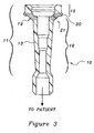
- the fluidic connector 10 comprises a tube connection site 11 at its proximal end and a patient connection site 12 at its distal end.
- the fluidic connector 10 further comprises a wall 13 that forms a hollow cavity 14 inside connector 10 that extends between both connection sites 11, 12 and permits fluid communication therethrough.
- the tube connection site 11 includes a first larger diameter portion 15 and a second smaller diameter portion 16.
- the first larger diameter portion 15 provides an area for closing off the tube connection site 11 with a plug while the second smaller diameter portion 16 provides a separate surface used for securely sealing, in an interference fit, a male adaptor (not shown) when the adaptor is inserted into the tube connection site 11.
- the first larger diameter portion 15 includes an opening 17 and a cap retaining groove 18 located below opening 17 for securely engaging the cap or plug upon insertion of a plug (not shown) into opening 17 therein.
- a cap retaining groove 18 located below opening 17 for securely engaging the cap or plug upon insertion of a plug (not shown) into opening 17 therein.
- the first larger diameter portion 15 is of sufficient diameter to allow a tight fit for the cap, while permitting sufficient clearance between an inner surface of portion 15 and the adaptor when the adaptor is inserted therein.
- the tube connection site 11 further includes a deformable buckling region 19 that forms a structural buffer zone between the first and second portions 15, 16.
- the deformable buckling region 19 the highlighted region of FIG. 3 that overlays a zone that partially includes both the first and second portions 15, 16 of the tube connection site 11 where the two portions 15, 16 join.
- the deformable buckling region 19 is the area beginning at an outer annular ridge 20 and ending where a curved portion 21 of the tube connection site 11 terminates.
- the outer annular ridge 20 serves to maintain the radial dimensional integrity of the first larger diameter portion 15 and provides termination of the buckling zone.
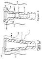
- FIGS. 4 and 5 the operation of the deformable buckling region will be explained.
- the original configuration of the prior art fluidic connector 1 before plastic deformation occurs is shown in solid while the configuration of that same connector 1 after the sealing and plugging portion 7 have been stretched out is shown in phantom.
- the deformable buckling region 19 the entire length of the sealing and plugging portion 7 is subject to stretching out. Leakage occurs when the opening 17 is plugged because the same surface is used to both plug the tube connection site 11 as well as to form a seal against the male adaptor.
- the fluidic connector 10 of the present invention is shown.
- the original configuration of the fluidic connector 10 before insertion of a male adapter into the smaller diameter portion 16 is shown in solid, while the configuration of the connector 10 after plastic deformation has occurred is shown in phantom.
- the second smaller diameter portion 16 is stretched radially or in the A direction, the deformable buckling region 19 deforms, with the deformation terminating at the outer annular ridge 20 and possibly resulting in translation of the first larger diameter portion 15 axially without affecting the size and shape of the larger diameter portion 15 with respect to it's plugging function.
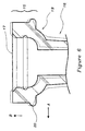
- FIG. 6 an enlarged view of the fluidic connector 10 with the deformable buckling region 19 is shown.
- a male connector (not shown) is inserted into the second smaller diameter portion 16, expanding portion 16 radially in the A direction.
- the buckling or unwrapping effect of the deformable buckling region 19 allows the portion of the first larger diameter portion 15 that is adjacent to the deformable buckling region 19 to be isolated from forces that would expand it radially, even in the absence of an outer annular ridge 20.
- the addition of one or more annular ridges 20 will further isolate the first larger diameter portion 15 from any forces which might expand it radially.
- the axial component of the deformation of the deformable buckling region 19 can result in a change in the overall length of the first larger diameter portion 15, either longer or shorter, depending on the specific configuration of the deformable buckling region 19.
- the net effect of this change in length which is shown in phantom in FIG. 6, is an axial translation of the first larger diameter portion 15 relative to the rest of the connection site. 11.
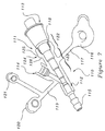
- the preferred embodiment consists of a Y-Site connector 110 comprising a tube connection site 111 at the proximal end of connector 110, a patient connection site 112 at the distal end of connector 110, and a flushing port 114 at the midpoint along connector 110 which is set at an angle in relation to the tube connection site 111.
- the tube connection site 111 has a male adaptor 113 inserted therein for connection to a lumen (not shown) while the patient connection site 112 is adapted to receive a barbed connector 115 for attachment to a lumen (not shown) leading to a patient.
- the Y-Site connector 110 also includes a cap 116 tethered to the tube connection site 111 by an arm member 117 and is used to plug the opening 118. Finally, a luer taper adaptor 120 in combination with a flushing port cap 121 is tethered to the flushing port 114 by a flushing port arm member 119.
- the tube connection site 111 further includes a first larger diameter portion 122 and a second smaller diameter portion 123 with a deformable buckling region 124 overlaying parts of both portions 122, 123 where portions 122, 123 join.
- the deformable buckling region 124 includes an outer annular ridge 125 and a curved portion 126 and functions in the same manner as explained above by acting as a buffer for the first larger diameter portion 122.
Landscapes
- Engineering & Computer Science (AREA)
- General Engineering & Computer Science (AREA)
- Health & Medical Sciences (AREA)
- Heart & Thoracic Surgery (AREA)
- Mechanical Engineering (AREA)
- Animal Behavior & Ethology (AREA)
- Anesthesiology (AREA)
- Biomedical Technology (AREA)
- Hematology (AREA)
- Life Sciences & Earth Sciences (AREA)
- Pulmonology (AREA)
- General Health & Medical Sciences (AREA)
- Public Health (AREA)
- Veterinary Medicine (AREA)
- Infusion, Injection, And Reservoir Apparatuses (AREA)
- Joints Allowing Movement (AREA)
- Rigid Pipes And Flexible Pipes (AREA)
- Non-Disconnectible Joints And Screw-Threaded Joints (AREA)
- Laying Of Electric Cables Or Lines Outside (AREA)
- Quick-Acting Or Multi-Walled Pipe Joints (AREA)
- Sealing Material Composition (AREA)
- Flanged Joints, Insulating Joints, And Other Joints (AREA)
Claims (11)
- Eine Verbindungsstelle (11, 111) für ein fluidtechnisches Verbindungsstück (10, 100), wobei die Verbindungsstelle (11, 111) einen inneren Abschnitt aufweist, und die Verbindungsstelle (11, 111) umfaßt:einen ersten Durchmesserabschnitt (15, 122);einen zweiten Durchmesserabschnitt (16, 123) angrenzend an den ersten Durchmesserabschnitt (15, 122), wobei der erste Durchmesserabschnitt (15, 122) einen größeren Durchmesser als der zweite Durchmesserabschnitt (16, 123) hat, und wobei der erste Durchmesserabschnitt (15, 122) ausgelegt ist, um dieselbe Form beizubehalten, wenn der Durchmesser des zweiten Durchmesserabschnitts (16, 123) vergrößert wird, dadurch gekennzeichnet, daß ein deformierbarer Bereich (19, 124) einen Teil der ersten (15, 122) und der zweiten (16, 123) Durchmesserabschnitte ausbildet, wobei der deformierbare Bereich (19, 124) ausgelegt ist, um sich auf eine solche Weise zu deformieren, daß, wenn der zweite Durchmesserabschnitt (16, 123) sich in eine radiale Richtung (A) dehnt, der erste Durchmesserabschnitt (15, 122) denselben Durchmesser beibehält.
- Die Verbindungsstelle (11, 111) nach Anspruch 1, wobei ein deformierbarer Bereich (19, 124) ferner einen oder mehrere äußere Wülste (20, 125) und einen gebogenen Abschnitt (21, 126) enthält, wobei der gebogene Abschnitt (21, 126) ausgelegt ist, um sich auf eine solche Weise zu dehnen, dass sich die äußeren Wülste (20, 125) axial verschieben und zum Abschluß der Deformation beitragen.
- Die Verbindungsstelle (11, 111) nach Anspruch 1 oder 2, wobei der erste Durchmesserabschnitt (15, 122) ausgelegt ist, um seinen ursprünglichen Durchmesser zu halten, wenn der deformierbare Bereich (19, 124) einer radialen Kraft ausgesetzt wird, und eine Verschiebung auf den inneren Abschnitt des fluidtechnischen Verbindungsstücks ausgeübt wird.
- Die Verbindungsstelle (11, 111) nach Anspruch 3, wobei die radiale Kraft auf den zweiten Durchmesserabschnitt (16, 123) des fluidtechnischen Verbindungsstücks (10, 110) ausgeübt wird.
- Die Verbindungsstelle (11, 111) nach Anspruch 3 oder Anspruch 4, wobei die von innerhalb des fluidtechnischen Verbindungsstücks (10, 110) ausgeübte Kraft von einem Anschlußstück herrührt, das in die Verbindungsstelle (11, 111) eingeführt ist, wobei das Anschlußstück eine radiale Kraft gegen den inneren Abschnitt ausübt.
- Die Verbindungsstelle (11, 111) nach Anspruch 5, wobei das Anschlußstück die radiale Kraft gegen den zweiten Durchmesserabschnitt ausübt.
- Die Verbindungsstelle (11, 111) nach einem der Ansprüche 1 bis 6, wobei der deformierbare Bereich ausgelegt ist, um sich auf solch eine Weise zu verbiegen, daß, wenn der zweite Durchmesserabschnitt (16, 123) sich in eine radiale Richtung (A) dehnt, sich der erste Durchmesser (15, 122) axial (B) verschiebt.
- Die Verbindungsstelle (11, 111) nach einem vorhergehenden Anspruch, wobei der zweite Durchmesserabschnitt (16, 123) mehrere Durchmessersegmente verschiedener Größe umfaßt, wobei der zweite Durchmesserabschnitt (16, 123) ausgelegt ist, um eine Reihe von verschiedenen Anschlußstücken mit verschiedenen Größen darin aufzunehmen.
- Die Verbindungsstelle (11, 111) für ein fluidtechnisches Verbindungsstück (10, 110, 130) nach einem vorhergehenden Anspruch, ferner mit:einem Luer-Adapter (132), der aufweist, einen abgestuften Rohrabschnitt (148), einen Rippenabschnitt (150), wobei mehrere Greifrippen (152) bereitgestellt sind, um zum Bereitstellen einer zuverlässigen Verbindung mit einem fluidtechnischen Verbindungsstück (10, 110, 130) zu dienen, einen Verschlussflansch (154), einen Zusammenbau-Haltebereich (156), und ein Verbindungsstück (158) zum Anschließen an eine Quelle.
- Die Verbindungsstelle (11, 111) für ein fluidtechnisches Verbindungsstück (10, 110, 130) nach Anspruch 9, ferner mit:einer Luer-Schürze (136), die auf dem Luer-Adapter (132) bei dem Zusammenbau-Haltebereich (156) angeordnet ist;einem Halteseil (138), das ein erstes Ende und ein zweites Ende aufweist, wobei das erste Ende des Halteseils (138) an den Luer-Adapter (132) bei dem Zusammenbau-Haltebereich (156) angeschlossen ist; unddem Luer-Deckel (140), der ein Außengewinde (146) aufweist, um das Innengewinde der Luer-Schürze (136) abnehmbar einzurasten.
- Eine Verbindungsstelle für ein fluidtechnisches verbindungsstück (10, 110, 130) nach Anspruch 9 oder Anspruch 10, wobei der Flansch (154) des Anschlussstücks (132) mit einem zylindrischen Abschnitt (155) ausgestattet ist, wobei der Flansch (154) angeschlossen ist, um eine redundante Dichtung gegen Undichtheit auszubilden, wenn das Anschlussstück (132) in das fluidtechnische Verbindungsstück (10, 110, 130) eingefügt ist.
Applications Claiming Priority (3)
| Application Number | Priority Date | Filing Date | Title |
|---|---|---|---|
| US858095P | 1995-12-13 | 1995-12-13 | |
| US8580P | 1995-12-13 | ||
| PCT/US1996/019773 WO1997021951A1 (en) | 1995-12-13 | 1996-12-11 | Leak proof tube connection site |
Publications (3)
| Publication Number | Publication Date |
|---|---|
| EP0809768A1 EP0809768A1 (de) | 1997-12-03 |
| EP0809768A4 EP0809768A4 (de) | 1998-03-25 |
| EP0809768B1 true EP0809768B1 (de) | 2002-07-03 |
Family
ID=21732419
Family Applications (1)
| Application Number | Title | Priority Date | Filing Date |
|---|---|---|---|
| EP96944324A Expired - Lifetime EP0809768B1 (de) | 1995-12-13 | 1996-12-11 | Dichte rohrverbindungsstelle |
Country Status (10)
| Country | Link |
|---|---|
| US (1) | US5988700A (de) |
| EP (1) | EP0809768B1 (de) |
| JP (1) | JPH11500818A (de) |
| KR (1) | KR19980702198A (de) |
| AT (1) | ATE220186T1 (de) |
| AU (1) | AU728294C (de) |
| BR (1) | BR9607451A (de) |
| DE (1) | DE69622151T2 (de) |
| PL (2) | PL182820B1 (de) |
| WO (1) | WO1997021951A1 (de) |
Cited By (4)
| Publication number | Priority date | Publication date | Assignee | Title |
|---|---|---|---|---|
| USD917690S1 (en) | 2016-06-10 | 2021-04-27 | Fisher & Paykel Healthcare Limited | Connector for a breathing circuit |
| USD940861S1 (en) | 2020-03-03 | 2022-01-11 | Fisher & Paykel Healthcare Limited | Connector for a respiratory system conduit |
| US11690995B2 (en) | 2011-08-10 | 2023-07-04 | Fisher & Paykel Healthcare Limited | Conduit connector for a patient breathing device |
| USD1006981S1 (en) | 2019-09-06 | 2023-12-05 | Fisher & Paykel Healthcare Limited | Breathing conduit |
Families Citing this family (41)
| Publication number | Priority date | Publication date | Assignee | Title |
|---|---|---|---|---|
| US6093179A (en) * | 1998-01-21 | 2000-07-25 | Abbott Laboratories | Apparatus and method for placement of a percutaneous endoscopic gastrostomy tube |
| US6808521B1 (en) * | 1999-11-18 | 2004-10-26 | Kimberly-Clark Worldwide, Inc. | Enteral feeding adapter |
| FR2801797B1 (fr) * | 1999-12-02 | 2002-11-08 | Cair L G L | Connecteur male non luer destine a equiper un premier dispositif medical en vue de son raccordement avec le connecteur femelle non luer correspondant d'un second dispositif medical |
| DE29922230U1 (de) * | 1999-12-17 | 2001-06-07 | Armaturenfabrik Hermann Voss GmbH + Co. KG, 51688 Wipperfürth | Leitungsverbinder insbesondere für Kraftstoffleitungen |
| WO2001070117A2 (en) * | 2000-03-23 | 2001-09-27 | Microheart, Inc. | Pressure sensor for therapeutic delivery device and method |
| US6908449B2 (en) * | 2000-12-19 | 2005-06-21 | Kimberly-Clark Worldwide, Inc. | Sealing valve assembly for medical products |
| US6767340B2 (en) | 2000-12-19 | 2004-07-27 | Kimberly-Clark Worldwide, Inc. | Sealing valve assembly for medical products |
| US20050187524A1 (en) * | 2000-12-19 | 2005-08-25 | Willis Allan F. | Sealing valve assembly for medical products |
| US20060108789A1 (en) * | 2004-11-10 | 2006-05-25 | Hughes Bryan L | Conduit repair fixture and method |
| US6913041B2 (en) * | 2002-10-15 | 2005-07-05 | Construction Forms, Inc. | Tapered boom hose |
| US20060129092A1 (en) * | 2002-10-28 | 2006-06-15 | Sherwood Services Ag | Single lumen adapter for automatic valve |
| US7097632B2 (en) * | 2002-10-28 | 2006-08-29 | Sherwood Services Ag | Automatic valve |
| US20050033269A1 (en) * | 2003-08-06 | 2005-02-10 | Kimberly-Clark Worldwide, Inc. | Ferrule and enteral tube incorporating a ferrule |
| US20050033268A1 (en) * | 2003-08-06 | 2005-02-10 | Kimberly-Clark Worldwide, Inc. | Connector with protrusion adapted for interconnection with second member |
| US20050245899A1 (en) * | 2003-10-28 | 2005-11-03 | Swisher David R | Dual purpose adapter |
| US20060253062A1 (en) * | 2005-04-26 | 2006-11-09 | Alcon, Inc. | Low resistance irrigation system and apparatus |
| US7896859B2 (en) | 2005-10-20 | 2011-03-01 | Tyco Healthcare Group Lp | Enteral feeding set |
| US7611502B2 (en) | 2005-10-20 | 2009-11-03 | Covidien Ag | Connector for enteral fluid delivery set |
| US20070209652A1 (en) * | 2006-03-13 | 2007-09-13 | Thompson David A | Barbecue chimney and utensil holder |
| US7981074B2 (en) * | 2006-11-02 | 2011-07-19 | Novartis Ag | Irrigation/aspiration system |
| US20080183153A1 (en) * | 2007-01-31 | 2008-07-31 | Benlan, Inc. | Enteral Feeding Tube Connector |
| JP2011500297A (ja) * | 2007-10-30 | 2011-01-06 | メデラ ホールディング アーゲー | 吸引チューブを接続するための装置 |
| US8631831B2 (en) | 2008-09-04 | 2014-01-21 | Alcon Research, Ltd. | Multi-compliant tubing |
| US9149387B2 (en) * | 2008-09-04 | 2015-10-06 | Novartis Ag | Varying material properties of a single fluidic line in ophthalmology tubing |
| KR101021493B1 (ko) * | 2009-03-25 | 2011-03-16 | 대경기업(주) | 테스트 커플링 |
| AU2012384552B2 (en) | 2012-07-05 | 2017-05-04 | Agilent Technologies, Inc. | Single-piece with undercut tapering part |
| USD735853S1 (en) * | 2012-09-24 | 2015-08-04 | Agilent Technologies, Inc. | Ferrule |
| US10763189B2 (en) | 2014-08-29 | 2020-09-01 | International Business Machines Corporation | Sealing arrangement |
| US10369083B2 (en) * | 2014-12-02 | 2019-08-06 | Kpr U.S., Llc | Adapter assembly for enteral feeding and method of making |
| US20160175577A1 (en) * | 2014-12-22 | 2016-06-23 | Anthony Solazzo | Ureteral Catheter Connector Adapter |
| KR20230156081A (ko) | 2015-03-31 | 2023-11-13 | 피셔 앤 페이켈 핼스케어 리미티드 | 호흡 보조 시스템용 장치 |
| CN113069659B (zh) | 2015-09-04 | 2025-04-04 | 费雪派克医疗保健有限公司 | 导管连接器 |
| US9765899B2 (en) * | 2015-11-03 | 2017-09-19 | Stoma Ventures, LLC | Disposable dental valve device |
| WO2017100621A1 (en) | 2015-12-11 | 2017-06-15 | Nxstage Medical, Inc. | Fluid line connector devices methods and systems |
| JP6732933B2 (ja) * | 2016-03-18 | 2020-07-29 | アヴェント インコーポレイテッド | 経腸栄養デバイスコネクタ |
| USD948027S1 (en) | 2019-09-10 | 2022-04-05 | Fisher & Paykel Healthcare Limited | Connector for a breathing conduit |
| USD974551S1 (en) | 2020-12-09 | 2023-01-03 | Fisher & Paykel Healthcare Limited | Connector assembly and connector |
| US11421806B1 (en) * | 2021-03-31 | 2022-08-23 | Sartorius Stedim North America Inc. | Fluid transfer connector |
| USD1073919S1 (en) | 2021-05-17 | 2025-05-06 | Fisher & Paykel Healthcare Limited | Respiratory system conduit with connector |
| USD995758S1 (en) | 2021-06-11 | 2023-08-15 | Fisher & Paykel Healthcare Limited | Tube assembly and connector |
| JP1780782S (ja) * | 2023-08-28 | 2024-09-26 | 医療用ホース継ぎ手 |
Family Cites Families (21)
| Publication number | Priority date | Publication date | Assignee | Title |
|---|---|---|---|---|
| GB190221415A (en) * | 1902-10-02 | 1902-11-20 | William Galt Highet | An Improvement in Soil and Drain Pipes. |
| US2025067A (en) * | 1934-12-17 | 1935-12-24 | Thomas S Miller | Tank filling device |
| US2186987A (en) * | 1938-08-05 | 1940-01-16 | Baxter Laboratories Inc | Filter flow device |
| US2507535A (en) * | 1946-04-03 | 1950-05-16 | Scamless Rubber Company | Connector |
| US2699357A (en) * | 1950-08-04 | 1955-01-11 | Charles M Roth | Faucet attachment for bubble bath |
| US2788231A (en) * | 1953-07-03 | 1957-04-09 | Howard M Crow | Conduit coupling having internal fluid expansible seal |
| FR1537833A (fr) * | 1967-07-12 | 1968-08-30 | Raccord en matière plastique | |
| BE876033A (fr) * | 1979-05-04 | 1979-09-03 | Ericson Sture | Dispositifs utilises pour le raccordement de tuyaux |
| US5776116A (en) * | 1983-01-24 | 1998-07-07 | Icu Medical, Inc. | Medical connector |
| USD297759S (en) | 1985-11-25 | 1988-09-20 | Kerschke Edson C | Fluid fitting |
| DE8713548U1 (de) * | 1987-10-09 | 1989-02-16 | Abflußrohrkontor GmbH & Co KG, 5000 Köln | Rohrverbinder |
| US5066286A (en) * | 1989-05-07 | 1991-11-19 | Ryan Medical, Inc. | Safety multiple sample luer adapter assembly |
| US5047021A (en) * | 1989-08-29 | 1991-09-10 | Utterberg David S | Male luer lock medical fitting |
| WO1991009643A1 (en) * | 1989-12-21 | 1991-07-11 | Medical Innovations Corporation | Ferrule and enteral tube incorporating a ferrule |
| US5242389A (en) * | 1990-07-19 | 1993-09-07 | Sherwood Medical Company | Enteral feeding tube enteral feeding tube with separate stylet lumen |
| US5267983A (en) * | 1992-04-22 | 1993-12-07 | Clintec Nutrition Co. | Enteral adapter and tip protector |
| US5284475A (en) * | 1992-07-21 | 1994-02-08 | Mackal Glenn H | Luer valve adapter with expandable end |
| US5201553A (en) * | 1992-10-09 | 1993-04-13 | Grisham William T | Pipe connector for washing machine drainage |
| US5385372A (en) * | 1993-01-08 | 1995-01-31 | Utterberg; David S. | Luer connector with integral closure |
| US5322515A (en) * | 1993-03-15 | 1994-06-21 | Abbott Laboratories | Luer adapter assembly for emergency syringe |
| US5620427A (en) * | 1995-04-27 | 1997-04-15 | David R. Kipp | Luer lock system |
-
1996
- 1996-12-11 DE DE69622151T patent/DE69622151T2/de not_active Expired - Lifetime
- 1996-12-11 PL PL96321753A patent/PL182820B1/pl not_active IP Right Cessation
- 1996-12-11 AU AU14161/97A patent/AU728294C/en not_active Expired
- 1996-12-11 WO PCT/US1996/019773 patent/WO1997021951A1/en not_active Ceased
- 1996-12-11 US US08/766,534 patent/US5988700A/en not_active Expired - Lifetime
- 1996-12-11 EP EP96944324A patent/EP0809768B1/de not_active Expired - Lifetime
- 1996-12-11 JP JP9522197A patent/JPH11500818A/ja active Pending
- 1996-12-11 AT AT96944324T patent/ATE220186T1/de active
- 1996-12-11 PL PL96346991A patent/PL183728B1/pl not_active IP Right Cessation
- 1996-12-11 KR KR1019970705593A patent/KR19980702198A/ko not_active Ceased
- 1996-12-11 BR BR9607451A patent/BR9607451A/pt not_active IP Right Cessation
Cited By (7)
| Publication number | Priority date | Publication date | Assignee | Title |
|---|---|---|---|---|
| US11690995B2 (en) | 2011-08-10 | 2023-07-04 | Fisher & Paykel Healthcare Limited | Conduit connector for a patient breathing device |
| US12544549B2 (en) | 2011-08-10 | 2026-02-10 | Fisher & Paykel Healthcare Limited | Conduit connector for a patient breathing device |
| USD917690S1 (en) | 2016-06-10 | 2021-04-27 | Fisher & Paykel Healthcare Limited | Connector for a breathing circuit |
| USD1027165S1 (en) | 2016-06-10 | 2024-05-14 | Fisher & Paykel Healthcare Limited | Connector for a breathing circuit |
| USD1028213S1 (en) | 2016-06-10 | 2024-05-21 | Fisher & Paykel Healthcare Limited | Connector for a breathing circuit |
| USD1006981S1 (en) | 2019-09-06 | 2023-12-05 | Fisher & Paykel Healthcare Limited | Breathing conduit |
| USD940861S1 (en) | 2020-03-03 | 2022-01-11 | Fisher & Paykel Healthcare Limited | Connector for a respiratory system conduit |
Also Published As
| Publication number | Publication date |
|---|---|
| DE69622151T2 (de) | 2003-03-06 |
| PL182820B1 (pl) | 2002-03-29 |
| JPH11500818A (ja) | 1999-01-19 |
| ATE220186T1 (de) | 2002-07-15 |
| PL321753A1 (en) | 1997-12-22 |
| PL183728B1 (pl) | 2002-07-31 |
| AU1416197A (en) | 1997-07-03 |
| WO1997021951A1 (en) | 1997-06-19 |
| AU728294B2 (en) | 2001-01-04 |
| EP0809768A1 (de) | 1997-12-03 |
| US5988700A (en) | 1999-11-23 |
| BR9607451A (pt) | 1998-06-30 |
| EP0809768A4 (de) | 1998-03-25 |
| KR19980702198A (ko) | 1998-07-15 |
| DE69622151D1 (de) | 2002-08-08 |
| AU728294C (en) | 2001-08-23 |
Similar Documents
| Publication | Publication Date | Title |
|---|---|---|
| EP0809768B1 (de) | Dichte rohrverbindungsstelle | |
| WO1997021951A9 (en) | Leak proof tube connection site | |
| US4013310A (en) | Tubing connector | |
| KR101343900B1 (ko) | 표준 관 피팅/포트를 삽입 연결식 관 피팅/포트로전환하는 연결장치 및 방법 | |
| US5160179A (en) | Pipe coupler with split ring chuck | |
| US7470262B2 (en) | Medical valve | |
| US20050033268A1 (en) | Connector with protrusion adapted for interconnection with second member | |
| GB2067075A (en) | Connector for connecting cannulae, catheters, flexible tubes or the like | |
| US5499848A (en) | Connection verifier for a quick connector coupling | |
| US20040178630A1 (en) | Pipe coupling | |
| US6302148B1 (en) | Coupling device | |
| EP0518679A2 (de) | Rohrkupplungs-Gehäuse | |
| CA2539428C (en) | Leak proof tube connection site | |
| CA2212807C (en) | Leak proof tube connection site | |
| CN217272077U (zh) | 一种可锁紧的多通道接头 | |
| JP2598300B2 (ja) | コレットを用いた管継手 | |
| AU6601686A (en) | Pipe connector device | |
| GB2227064A (en) | Snap-fit pipe connector | |
| RU2171949C2 (ru) | Соединительный участок для соединителя трубки для жидкости (варианты) и переходное устройство для него | |
| EP0555927A1 (de) | Verbindungselement sowie Beutel mit einem solchen Element | |
| CA1296961C (en) | Reverse taper spike connector | |
| JPH03265789A (ja) | 管継手 | |
| CN113712649B (zh) | 闭孔器 | |
| CN2451858Y (zh) | 快速管接头 | |
| KR100190887B1 (ko) | 에어라인용 커넥터 연결 구조 |
Legal Events
| Date | Code | Title | Description |
|---|---|---|---|
| PUAI | Public reference made under article 153(3) epc to a published international application that has entered the european phase |
Free format text: ORIGINAL CODE: 0009012 |
|
| 17P | Request for examination filed |
Effective date: 19970822 |
|
| AK | Designated contracting states |
Kind code of ref document: A1 Designated state(s): AT BE CH DE ES FI FR GB IE IT LI LU MC NL PT SE |
|
| A4 | Supplementary search report drawn up and despatched |
Effective date: 19980203 |
|
| AK | Designated contracting states |
Kind code of ref document: A4 Designated state(s): AT BE CH DE ES FI FR GB IE IT LI LU MC NL PT SE |
|
| 17Q | First examination report despatched |
Effective date: 19991118 |
|
| RAP1 | Party data changed (applicant data changed or rights of an application transferred) |
Owner name: SHERWOOD SERVICES AG |
|
| GRAG | Despatch of communication of intention to grant |
Free format text: ORIGINAL CODE: EPIDOS AGRA |
|
| GRAG | Despatch of communication of intention to grant |
Free format text: ORIGINAL CODE: EPIDOS AGRA |
|
| GRAH | Despatch of communication of intention to grant a patent |
Free format text: ORIGINAL CODE: EPIDOS IGRA |
|
| GRAH | Despatch of communication of intention to grant a patent |
Free format text: ORIGINAL CODE: EPIDOS IGRA |
|
| GRAA | (expected) grant |
Free format text: ORIGINAL CODE: 0009210 |
|
| AK | Designated contracting states |
Kind code of ref document: B1 Designated state(s): AT BE CH DE ES FI FR GB IE IT LI LU MC NL PT SE |
|
| PG25 | Lapsed in a contracting state [announced via postgrant information from national office to epo] |
Ref country code: NL Free format text: LAPSE BECAUSE OF FAILURE TO SUBMIT A TRANSLATION OF THE DESCRIPTION OR TO PAY THE FEE WITHIN THE PRESCRIBED TIME-LIMIT Effective date: 20020703 Ref country code: FI Free format text: LAPSE BECAUSE OF FAILURE TO SUBMIT A TRANSLATION OF THE DESCRIPTION OR TO PAY THE FEE WITHIN THE PRESCRIBED TIME-LIMIT Effective date: 20020703 |
|
| REF | Corresponds to: |
Ref document number: 220186 Country of ref document: AT Date of ref document: 20020715 Kind code of ref document: T |
|
| REG | Reference to a national code |
Ref country code: CH Ref legal event code: EP |
|
| REG | Reference to a national code |
Ref country code: IE Ref legal event code: FG4D |
|
| REF | Corresponds to: |
Ref document number: 69622151 Country of ref document: DE Date of ref document: 20020808 |
|
| REG | Reference to a national code |
Ref country code: CH Ref legal event code: NV Representative=s name: KELLER & PARTNER PATENTANWAELTE AG |
|
| PG25 | Lapsed in a contracting state [announced via postgrant information from national office to epo] |
Ref country code: SE Free format text: LAPSE BECAUSE OF FAILURE TO SUBMIT A TRANSLATION OF THE DESCRIPTION OR TO PAY THE FEE WITHIN THE PRESCRIBED TIME-LIMIT Effective date: 20021003 Ref country code: PT Free format text: LAPSE BECAUSE OF FAILURE TO SUBMIT A TRANSLATION OF THE DESCRIPTION OR TO PAY THE FEE WITHIN THE PRESCRIBED TIME-LIMIT Effective date: 20021003 |
|
| NLV1 | Nl: lapsed or annulled due to failure to fulfill the requirements of art. 29p and 29m of the patents act | ||
| ET | Fr: translation filed | ||
| PG25 | Lapsed in a contracting state [announced via postgrant information from national office to epo] |
Ref country code: ES Free format text: LAPSE BECAUSE OF FAILURE TO SUBMIT A TRANSLATION OF THE DESCRIPTION OR TO PAY THE FEE WITHIN THE PRESCRIBED TIME-LIMIT Effective date: 20030130 |
|
| PLBE | No opposition filed within time limit |
Free format text: ORIGINAL CODE: 0009261 |
|
| STAA | Information on the status of an ep patent application or granted ep patent |
Free format text: STATUS: NO OPPOSITION FILED WITHIN TIME LIMIT |
|
| 26N | No opposition filed |
Effective date: 20030404 |
|
| REG | Reference to a national code |
Ref country code: CH Ref legal event code: PFA Owner name: COVIDIEN AG Free format text: SHERWOOD SERVICES AG#SCHWERTSTRASSE 9#8200 SCHAFFHAUSEN (CH) -TRANSFER TO- COVIDIEN AG#VICTOR VON BRUNS-STRASSE 19#8212 NEUHAUSEN AM RHEINFALL (CH) |
|
| PGFP | Annual fee paid to national office [announced via postgrant information from national office to epo] |
Ref country code: MC Payment date: 20071121 Year of fee payment: 12 |
|
| PGFP | Annual fee paid to national office [announced via postgrant information from national office to epo] |
Ref country code: LU Payment date: 20080107 Year of fee payment: 12 |
|
| REG | Reference to a national code |
Ref country code: FR Ref legal event code: CD Ref country code: FR Ref legal event code: CA |
|
| PG25 | Lapsed in a contracting state [announced via postgrant information from national office to epo] |
Ref country code: MC Free format text: LAPSE BECAUSE OF NON-PAYMENT OF DUE FEES Effective date: 20081231 |
|
| PGFP | Annual fee paid to national office [announced via postgrant information from national office to epo] |
Ref country code: IE Payment date: 20071224 Year of fee payment: 12 |
|
| REG | Reference to a national code |
Ref country code: IE Ref legal event code: MM4A |
|
| PG25 | Lapsed in a contracting state [announced via postgrant information from national office to epo] |
Ref country code: IE Free format text: LAPSE BECAUSE OF NON-PAYMENT OF DUE FEES Effective date: 20081211 |
|
| PG25 | Lapsed in a contracting state [announced via postgrant information from national office to epo] |
Ref country code: LU Free format text: LAPSE BECAUSE OF NON-PAYMENT OF DUE FEES Effective date: 20081211 |
|
| PGFP | Annual fee paid to national office [announced via postgrant information from national office to epo] |
Ref country code: BE Payment date: 20111227 Year of fee payment: 16 |
|
| BERE | Be: lapsed |
Owner name: COVIDIEN A.G. Effective date: 20121231 |
|
| PG25 | Lapsed in a contracting state [announced via postgrant information from national office to epo] |
Ref country code: BE Free format text: LAPSE BECAUSE OF NON-PAYMENT OF DUE FEES Effective date: 20121231 |
|
| REG | Reference to a national code |
Ref country code: CH Ref legal event code: PCAR Free format text: NEW ADDRESS: EIGERSTRASSE 2 POSTFACH, 3000 BERN 14 (CH) |
|
| REG | Reference to a national code |
Ref country code: FR Ref legal event code: PLFP Year of fee payment: 20 |
|
| PGFP | Annual fee paid to national office [announced via postgrant information from national office to epo] |
Ref country code: CH Payment date: 20151119 Year of fee payment: 20 Ref country code: IT Payment date: 20151120 Year of fee payment: 20 Ref country code: GB Payment date: 20151125 Year of fee payment: 20 Ref country code: DE Payment date: 20151119 Year of fee payment: 20 |
|
| PGFP | Annual fee paid to national office [announced via postgrant information from national office to epo] |
Ref country code: AT Payment date: 20151120 Year of fee payment: 20 Ref country code: FR Payment date: 20151123 Year of fee payment: 20 |
|
| REG | Reference to a national code |
Ref country code: DE Ref legal event code: R071 Ref document number: 69622151 Country of ref document: DE |
|
| REG | Reference to a national code |
Ref country code: CH Ref legal event code: PL |
|
| REG | Reference to a national code |
Ref country code: GB Ref legal event code: PE20 Expiry date: 20161210 |
|
| REG | Reference to a national code |
Ref country code: AT Ref legal event code: MK07 Ref document number: 220186 Country of ref document: AT Kind code of ref document: T Effective date: 20161211 |
|
| PG25 | Lapsed in a contracting state [announced via postgrant information from national office to epo] |
Ref country code: GB Free format text: LAPSE BECAUSE OF EXPIRATION OF PROTECTION Effective date: 20161210 |