EP0809580B1 - Device for transmitting electrical signals between components which can be rotated relative to one another - Google Patents
Device for transmitting electrical signals between components which can be rotated relative to one another Download PDFInfo
- Publication number
- EP0809580B1 EP0809580B1 EP95942640A EP95942640A EP0809580B1 EP 0809580 B1 EP0809580 B1 EP 0809580B1 EP 95942640 A EP95942640 A EP 95942640A EP 95942640 A EP95942640 A EP 95942640A EP 0809580 B1 EP0809580 B1 EP 0809580B1
- Authority
- EP
- European Patent Office
- Prior art keywords
- hub
- electric lead
- chamber
- rotatable
- loop
- Prior art date
- Legal status (The legal status is an assumption and is not a legal conclusion. Google has not performed a legal analysis and makes no representation as to the accuracy of the status listed.)
- Expired - Lifetime
Links
Images


Classifications
-
- B—PERFORMING OPERATIONS; TRANSPORTING
- B60—VEHICLES IN GENERAL
- B60R—VEHICLES, VEHICLE FITTINGS, OR VEHICLE PARTS, NOT OTHERWISE PROVIDED FOR
- B60R16/00—Electric or fluid circuits specially adapted for vehicles and not otherwise provided for; Arrangement of elements of electric or fluid circuits specially adapted for vehicles and not otherwise provided for
- B60R16/02—Electric or fluid circuits specially adapted for vehicles and not otherwise provided for; Arrangement of elements of electric or fluid circuits specially adapted for vehicles and not otherwise provided for electric constitutive elements
- B60R16/023—Electric or fluid circuits specially adapted for vehicles and not otherwise provided for; Arrangement of elements of electric or fluid circuits specially adapted for vehicles and not otherwise provided for electric constitutive elements for transmission of signals between vehicle parts or subsystems
- B60R16/027—Electric or fluid circuits specially adapted for vehicles and not otherwise provided for; Arrangement of elements of electric or fluid circuits specially adapted for vehicles and not otherwise provided for electric constitutive elements for transmission of signals between vehicle parts or subsystems between relatively movable parts of the vehicle, e.g. between steering wheel and column
-
- H—ELECTRICITY
- H01—ELECTRIC ELEMENTS
- H01R—ELECTRICALLY-CONDUCTIVE CONNECTIONS; STRUCTURAL ASSOCIATIONS OF A PLURALITY OF MUTUALLY-INSULATED ELECTRICAL CONNECTING ELEMENTS; COUPLING DEVICES; CURRENT COLLECTORS
- H01R35/00—Flexible or turnable line connectors, i.e. the rotation angle being limited
- H01R35/02—Flexible line connectors without frictional contact members
- H01R35/025—Flexible line connectors without frictional contact members having a flexible conductor wound around a rotation axis
Definitions
- the invention relates to a device according to the preamble of claim 1.
- Such transmission facilities are used, for example, in vehicle steering systems, around the signals of the functional elements arranged on or in the steering wheel transferred to.
- DE-OS 35 37 783 is a device for signal transmission shown in which an electrical line on a fixed and a rotatable component is attached. There is a between the stationary and the rotatable component arranged with a recessed loose guide ring.
- the electrical line is at least partially around Guide ring around and through the recess of the guide ring guided and is within the guide ring around that rotatable component can be wound.
- the wound part and the part around the guide ring become part of the component guided part of the electrical line each shortened or lengthened so that the guide ring accordingly the movement of the electrical line is rotated.
- the electrical line is open the rotatable component, in the other extreme position the electrical line is unwound and between the guide ring and the stationary component.
- the device described in DE-OS 35 37 783 for Signal transmission has the disadvantage that the possible Rotational movement compared to the length of the electrical Line is low.
- DE-A-4 111 699 is a transmission device known for the effective length of a flexible electrical conductor is reduced without the number of the rotations of the rotor must be reduced. Reached is that by a in the space between the rotor and a fixed housing arranged intermediate link, which in rotates in the same direction and in synchronism with the rotor, and on which a guide roller is rotatably mounted.
- the invention is therefore based on the object of a device for transmitting electrical signals between to create mutually rotatable components in which the necessary length of the electrical line for one predetermined range of rotation compared to previously known solutions is reduced.
- the electrical line connections and the routing of the electrical line is carried out that the electrical line in the two end positions of the hub when rotating the hub clockwise or counterclockwise Clockwise in the opposite direction the hub is wound up while the electrical wire is unwound from the hub in the middle position.
- a first chamber for receiving the electrical wound on the hub Line and a second chamber for the processed, loop-shaped electrical line provided.
- the loop of the electrical line only by 180 °.
- the housing can be on the opposite side of this room Side omitted.
- This free space can e.g. in a steering spindle can be used for other components.
- the chambers is in one embodiment between the hub and a fixed housing fixed annular partition with an opening for the implementation of the electrical line provided and on the outside of the partition is next to the opening electrical line connection provided.
- the first chamber is then formed between the hub and the bulkhead while the second chamber concentrically between them the fixed housing and the partition.
- the electrical line is in the two extreme positions the first chamber wound on the hub while in the middle position of the hub as a loop in the second Chamber lies.
- the second chamber provided on the side of the fixed housing and at the transition the first in the second chamber is the electrical one Line connection provided on a fixed Component is to be attached.
- the first chamber is the space between the fixed housing and the hub.
- the second chamber closes the first chamber on the side. In the middle position of the hub the electrical cable is in the form of a loop lateral second chamber.
- Loop guide can be a connector between the fixed housing and the partition be provided.
- Another expedient embodiment of the invention provides before that the loop of the electrical wire permanent tensile element is provided. In order to is achieved that in the absence of a torque on the Hub is held in its middle position.
- Tension element can e.g. a tension spring can be provided.
- the hub-side electrical line connection is rotatably attached to the hub and in particular rotatable about an axis parallel to the hub axis is.
- the housing of the device according to the invention has in an embodiment a circular cross section on.
- the housing an annular cross section with one on one Side on a string of the circle-trending flat wall on.
- this is a section opposite to that with circular Cross-section has been reduced for the unwound Cable is not needed.
- This gained space can e.g. B. when used on a steering column of a motor vehicle can be used for the installation of other components.
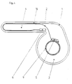
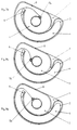
- the device according to the invention has a housing 1 and a hub 9, e.g. B. a steering wheel hub, between which an electrical line 2 extends. Between the Hub 9 and housing 1 are concentric with hub 9 and to the housing 1 a fixed partition 10, whereby an inner first chamber 3 and an outer second Chamber 4 are formed, which are concentric with each other lie.
- the intermediate wall 10 has an opening 11, through which the electrical line 2 is guided.
- the hub 9 is in a central position.
- this line 2 is completely from the hub unwound and extends through the opening 11 of a line connection 5 on the hub 9 in the second chamber 4.
- the line is a loop in this chamber the wall of the housing 1 and the intermediate wall 10 into one Line connection 6 guided on the fixed partition.
- the line connections 5 and 6 are in this Middle position of the hub 9 directly opposite.
- Fig. 2 shows the hub in this direction of rotation in its end position. The line is now almost completely wound on the hub 9.
- FIG. 1a there is a housing 21 provided that essentially as in FIGS. 1 to 3 has a circular cylindrical cross section, which on a But side is flattened so that there is a flat wall 22.
- the partition also extends from this 10a in the direction of the hub 9.
- the first chamber 3 is therefore in contrast to the exemplary embodiment in FIGS. 1 to 3 not just from the partition but from the partition 10a and the flat wall 22 formed as part of the housing.
- the flattening of the cylinder cross section next to the flat one Wall 22 created free space can be used for housing other components can be used.
- Figures 2a and 3a show the hub 9 in both in analogy to FIGS. 2 and 3 Direction of rotation in its end position.
- FIG. 4 shows again the Center position of the hub, in which the line from the hub is unwound and is a loop in the second chamber located.
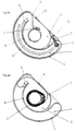
- FIG. 5 is an intermediate wall 10 provided, which is provided with a loop guide.
- a connector 8 between serves as a loop guide the housing 1 and the intermediate wall 10. Through this connector 8 will guide the loop in the second Chamber further improved.
- a tension spring 7 is provided, which strives to Loop in the second chamber in its end position and thereby to keep the hub 9 in its central position.
- the mainspring is attached to two bolts 12, 13. During the bolt 12 is firmly arranged in the housing, the bolt 13 can within the second chamber 4 along a guideway 14 move.
- the hub 9 is shown in its central position, in which the line is almost completely in Loop shape is located in the second chamber 4.
- This Middle position is due to the almost relaxed tension spring 7 fixed, which is shown here in simplified form.
- the hub 9 When turning the hub 9 clockwise or counterclockwise the line is pulled out of the chamber 4 and wound as shown in Fig. 6 for the clockwise rotation, on the hub 9.
- the loop takes the Bolt 13 with, whereby the tension spring 7 is tensioned.
- the tensioned tension spring will return the hub into the Supported center position, in which the mainspring is again in the position shown in Fig. 5.
- FIGS. 5 and 6 show Figures 5a and 6a.
- this embodiment is similar to the embodiment of Figures 1a to 3a shows a housing with a circular cylinder cross section flattened on one side intended. That forms on this side Connector 8 between the housing 1 and the partition 10 simultaneously the housing wall.
- FIG. 6a shows the hub 9 in a simplified representation in their end position when turning clockwise.
- the line is laid when the hub 9 is turned clockwise at line connection 5 directly from the connection point from the tangential direction to the hub.
- the hub 9 turns counterclockwise the line first deflected by approx. 180 ° and only then lies down the hub on.
- the line connection 6 is in the embodiment 1 to 3 the line at on the hub 9 coiled line in both directions of rotation Connection point deflected by 180 °. The line will go to Line connections 5 and 6 in these cases additionally Bending stressed.
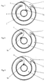
- Fig. 8 shows that counter to the beginning of the rotation of the hub clockwise the line connection 5 through the Line 9 is rotated into a right position, so that too in this direction of rotation onto the line at the connection point because of the tangential contact with the hub only pulling forces act.
- Figures 10 to 12 is the position of the rotatable Line connection 6a for different hub positions shown. 10 shows the center position of the hub, in which the line routing at line connection 6a Line routing at line connection 6 in FIG. 1 corresponds. In the end position shown in FIG The hub when turning counterclockwise is the Line connection rotated by 180 °, so that the line only around Is bent 180 ° while in the comparable position 2 must be bent through approximately 360 ° to the hub to lie on.
Landscapes
- Engineering & Computer Science (AREA)
- Mechanical Engineering (AREA)
- Steering Controls (AREA)
- Near-Field Transmission Systems (AREA)
- Power Steering Mechanism (AREA)
Description
Die Erfindung betrifft eine Einrichtung nach dem Oberbegriff
des Anspruchs 1. Solche Übertragungseinrichtungen
werden beispielsweise in Kraftfahrzeuglenkungen eingesetzt,
um die Signale der am oder im Lenkrad angeordneten Funktionselemente
zu übertragen. The invention relates to a device according to the preamble
of
In der DE-OS 35 37 783 ist eine Einrichtung zur Signalübertragung gezeigt, bei der eine elektrische Leitung an einem ortsfesten und einem drehbaren Bauteil angebracht ist. Zwischen dem ortsfesten und dem drehbaren Bauteil ist ein mit einer Aussparung versehener loser Führungsring angeordnet. Die elektrische Leitung ist zumindest teilweise um den Führungsring herum und durch die Aussparung des Führungsringes geführt und ist innerhalb des Führungsringes um das drehbare Bauteil wickelbar. Bei einer Drehung des drehbaren Bauteils wird der aufgewickelte Teil und der um den Führungsring geführte Teil der elektrischen Leitung jeweils verkürzt oder verlängert, so daß der Führungsring entsprechend der Bewegung der elektrischen Leitung gedreht wird. In der einen Extremstellung ist die elektrische Leitung auf dem drehbaren Bauteil aufgewickelt, in der anderen Extremstellung ist die elektrische Leitung abgewickelt und zwischen dem Führungsring und dem ortsfesten Bauteil geführt.DE-OS 35 37 783 is a device for signal transmission shown in which an electrical line on a fixed and a rotatable component is attached. There is a between the stationary and the rotatable component arranged with a recessed loose guide ring. The electrical line is at least partially around Guide ring around and through the recess of the guide ring guided and is within the guide ring around that rotatable component can be wound. When the rotatable The wound part and the part around the guide ring become part of the component guided part of the electrical line each shortened or lengthened so that the guide ring accordingly the movement of the electrical line is rotated. In one extreme position, the electrical line is open the rotatable component, in the other extreme position the electrical line is unwound and between the guide ring and the stationary component.
Die in der DE-OS 35 37 783 beschriebene Einrichtung zur Signalübertragung besitzt den Nachteil, daß die mögliche Drehbewegung verglichen mit der Länge der elektrischen Leitung gering ist.The device described in DE-OS 35 37 783 for Signal transmission has the disadvantage that the possible Rotational movement compared to the length of the electrical Line is low.
Um den Drehbereich für eine Einrichtung zur Signalübertragung zu vergrößern, ist aus der EP-0 186 935 bekannt, eine elektrische Leitung in einem Raum zwischen einer drehbaren Habe und einer festen Gehäusewand zu führen. Dabei ist die elektrische Leitung bei einer Drehung der Nabe in Uhrzeigerrichtung in der Endstellung vollständig von der Nabe abgewickelt und liegt zu einem Teil an der Innenwand des feststehenden Gehäuses an oder befindet sich in dem Raum zwischen der Nabe und dem feststehenden Gehäuse. Bei Drehung der Nabe entgegen der Uhrzeigerrichtung ist die elektrische Leitung in der Endstellung der Nabe vollständig auf dieser aufgewickelt. In der Mittelstellung ist die elektrische Leitung teilweise auf der Nabe aufgewickelt.Around the rotation range for a device for signal transmission to enlarge, is known from EP-0 186 935, a electrical wire in a space between a rotatable Have and a solid housing wall. Here is the electrical cable when the hub rotates clockwise completely unwound from the hub in the end position and is partly on the inner wall of the fixed On or in the space between the hub and the fixed housing. When turning the counterclockwise hub is the electrical one Line in the end position of the hub completely on this wound up. In the middle position is the electrical one Line partially coiled on the hub.
Bei der letztgenannten Leiteranordnung ist zwar der Drehbereich gegenüber der vorher genannten Anordnung größer. Hierbei besteht aber der Nachteil, daß eine große Leitunglänge erforderlich ist.In the last-mentioned conductor arrangement, the range of rotation is indeed larger than the above arrangement. However, there is the disadvantage that a long line length is required.
Weiterhin ist aus der DE-A-4 111 699 eine Übertragungsvorrichtung bekannt, bei der die effektive Länge eines flexiblen elektrischen Leiters verringert ist, ohne daß die Zahl der Umdrehungen des Rotors vermindert werden muß. Erreicht wird das durch ein im Raum zwischen dem Rotor und einem feststehenden Gehäuse angeordnetes Zwischenglied, das in derselben Richtung und synchron mit dem Rotor umläuft, und auf dem eine Führungsrolle drehbar gelagert ist.Furthermore, DE-A-4 111 699 is a transmission device known for the effective length of a flexible electrical conductor is reduced without the number of the rotations of the rotor must be reduced. Reached is that by a in the space between the rotor and a fixed housing arranged intermediate link, which in rotates in the same direction and in synchronism with the rotor, and on which a guide roller is rotatably mounted.
Der Erfindung liegt daher die Aufgabe zugrunde, eine Einrichtung zum Übertragen elektrischer Signale zwischen gegeneinander verdrehbaren Bauteilen zu schaffen, bei der die notwendige Länge der elektrischen Leitung für einen vorgegebenen Drehbereich gegenüber bisher bekannten Lösungen verringert wird.The invention is therefore based on the object of a device for transmitting electrical signals between to create mutually rotatable components in which the necessary length of the electrical line for one predetermined range of rotation compared to previously known solutions is reduced.
Diese Aufgabe wird erfindungsgemäß durch den kennzeichnenden
Teil des Anspruchs 1 gelöst. This object is achieved by the characterizing
Part of
Bei der Einrichtung zur Übertragung elektrischer Signale gemäß der Erfindung sind die elektrischen Leitungsanschlüsse und die Führung der elektrischen Leitung so ausgeführt, daß die elektrische Leitung in den beiden Endlagen der Nabe bei Drehung der Nabe in Uhrzeigerrichtung bzw. entgegen der Uhrzeigerrichtung in jeweils entgegengesetzter Richtung auf der Nabe aufgewickelt ist, während die elektrische Leitung in der Mittelstellung der Nabe von dieser abgewickelt ist.In the device for transmitting electrical signals according to the invention are the electrical line connections and the routing of the electrical line is carried out that the electrical line in the two end positions of the hub when rotating the hub clockwise or counterclockwise Clockwise in the opposite direction the hub is wound up while the electrical wire is unwound from the hub in the middle position.
Gegenüber bekannten Einrichtungen zur Signalübertragung der genannten Art ergibt sich der Vorteil, daß für die notwendige Drehung der Nabe eine geringere Leitungslänge erforderlich ist. Compared to known devices for signal transmission mentioned type there is the advantage that for the necessary Rotation of the hub requires a shorter cable length is.
In einer bevorzugten Ausführungsform ist eine erste Kammer für die Aufnahme der auf der Nabe aufgewickelten elektrischen Leitung und eine zweite Kammer für die abgewickelte, schlaufenförmig verlaufende elektrische Leitung vorgesehen. Für eine herkömmliche Anzahl von Umdrehungen bei Lenkspindeln bewegt sich bei der erfindungsgemäßen Einrichtung die Schlaufe der elektrischen Leitung nur um 180°. Dadurch kann das Gehäuse auf der diesem Raum gegenüberliegenden Seite entfallen. Dieser Freiraum kann z.B. in einer Lenkspindel für andere Bauteile genutzt werden.In a preferred embodiment is a first chamber for receiving the electrical wound on the hub Line and a second chamber for the processed, loop-shaped electrical line provided. For a conventional number of turns on steering spindles moves in the device according to the invention the loop of the electrical line only by 180 °. Thereby the housing can be on the opposite side of this room Side omitted. This free space can e.g. in a steering spindle can be used for other components.
Zur Realisierung der Kammern ist in einer Ausführungsform zwischen der Nabe und einem feststehenden Gehäuse eine feststehende ringförmige Zwischenwand mit einer Öffnung für die Durchführung der elektrischen Leitung vorgesehen und an der Außenseite der Zwischenwand ist neben der Öffnung ein elektrischer Leitunganschluß vorgesehen. Die erste Kammer wird dann zwischen der Nabe und der Zwischenwand gebildet, während sich die zweite Kammer konzentrisch dazu zwischen dem feststehenden Gehäuse und der Zwischenwand befindet. In den beiden Extremstellungen ist die elektrische Leitung in der ersten Kammer auf der Nabe aufgewickelt, während sie in der Mittelstellung der Nabe als Schlaufe in der zweiten Kammer liegt.To realize the chambers is in one embodiment between the hub and a fixed housing fixed annular partition with an opening for the implementation of the electrical line provided and on the outside of the partition is next to the opening electrical line connection provided. The first chamber is then formed between the hub and the bulkhead while the second chamber concentrically between them the fixed housing and the partition. In The electrical line is in the two extreme positions the first chamber wound on the hub while in the middle position of the hub as a loop in the second Chamber lies.
In einer weiteren Ausführungsform ist die zweite Kammer seitlich am feststehenden Gehäuse vorgesehen und am Übergang der ersten in die zweite Kammer ist in dieser der elektrische Leitungsanschluß vorgesehen, der an einem feststehenden Bauteil anzubringen ist. In dieser Ausführungsform ist die erste Kammer der Raum zwischen dem feststehenden Gehäuse und der Nabe. Die zweite Kammer schließt sich der ersten Kammer seitlich an. In der Mittelstellung der Nabe liegt die elektrische Leitung in Schlaufenform in dieser seitlichen zweiten Kammer. In a further embodiment, the second chamber provided on the side of the fixed housing and at the transition the first in the second chamber is the electrical one Line connection provided on a fixed Component is to be attached. In this embodiment the first chamber is the space between the fixed housing and the hub. The second chamber closes the first chamber on the side. In the middle position of the hub the electrical cable is in the form of a loop lateral second chamber.
Zur Unterstützung der Ausbildung einer Schlaufe beim Abwickeln der elektrischen Leitung von der Nabe ist es zweckmäßig, in der zweiten Kammer eine Schlaufenführung zur Bestimmung der Laufrichtung der Schlaufe vorzusehen. Als Schlaufenführung kann ein Verbindungsstück zwischen dem feststehenden Gehäuse und der Zwischenwand vorgesehen sein.To support the formation of a loop when unwinding the electrical cable from the hub it is advisable in the second chamber a loop guide for Determine the direction of the loop. As Loop guide can be a connector between the fixed housing and the partition be provided.
In allen Fällen liegt der Umkehrpunkt der Schlaufe in einem Bereich außerhalb der elektrischen Leitunganschlüsse, so daß optimale Abrollverhältnisse für die Schlaufe möglich sind.In all cases, the point of reversal of the loop lies in one Area outside the electrical line connections, see above that optimal unwinding conditions for the loop are possible are.
Eine weitere zweckmäßige Ausgestaltung der Erfindung sieht vor, daß ein die Schlaufe der elektrischen Leitung permanent auf Zug beanspruchendes Element vorgesehen ist. Damit wird erreicht, daß bei Fehlen eines Drehmomentes an der Nabe diese in ihrer Mittelstellung gehalten wird. Als Zugelement kann z.B. eine Zugfeder vorgesehen sein.Another expedient embodiment of the invention provides before that the loop of the electrical wire permanent tensile element is provided. In order to is achieved that in the absence of a torque on the Hub is held in its middle position. As Tension element can e.g. a tension spring can be provided.
Um die Biegebelastung der elektrischen Leitung bei deren Aufwickeln in unterschiedliche Richtungen zu verringern, ist es zweckmäßig, daß der nabenseitige elektrische Leitungsanschluß drehbar an der Nabe befestigt ist und insbesondere um eine zur Nabenachse parallele Achse drehbar ist.To the bending stress of the electrical line at its To reduce winding in different directions, it is appropriate that the hub-side electrical line connection is rotatably attached to the hub and in particular rotatable about an axis parallel to the hub axis is.
Aus dem gleichen Grund ist es zweckmäßig, daß auch der elektrische Leitungsanschluß auf dem feststehenden Bauteil drehbar gelagert ist und daß er insbesondere um eine zur Nabenachse parallele Achse drehbar gelagert ist. For the same reason, it is appropriate that the electrical line connection on the fixed component is rotatably mounted and that in particular by one to Hub axis parallel axis is rotatably mounted.
Das Gehäuse der erfindungsgemäßen Einrichtung weist in einer Ausführungsform einen kreisringförmigen Querschnitt auf. In einer weiteren Ausführungsform weist das Gehäuse einen kreisringförmigen Querschnitt mit einer an einer Seite auf einer Sehne des Kreises verlaufenden ebenen Wand auf. In dieser letztgenannten Ausführungsform des Gehäuses ist dieses um einen Abschnitt gegenüber dem mit kreisförmigem Querschnitt verkleinert worden, der für das abgewickelte Kabel nicht benötigt wird. Dieser gewonnene Raum kann z. B. bei Anwendung an einer Lenksäule eines Kraftfahrzeuges für den Einbau anderer Bauteile genutzt werden.The housing of the device according to the invention has in an embodiment a circular cross section on. In a further embodiment, the housing an annular cross section with one on one Side on a string of the circle-trending flat wall on. In this latter embodiment of the housing this is a section opposite to that with circular Cross-section has been reduced for the unwound Cable is not needed. This gained space can e.g. B. when used on a steering column of a motor vehicle can be used for the installation of other components.
Die Erfindung soll in Ausführungsbeispielen anhand von Zeichnungen erläutert werden:The invention is intended to be used in exemplary embodiments on the basis of Drawings are explained:
Es zeigen:
- Fig. 1 und 1a
- eine erfindungsgemäße Einrichtung in zwei Ausführungsformen mit einer Wand zwischen einer drehbaren Nabe und einem feststehenden Gehäuse wobei sich die Nabe in einer Mittelstellung befindet;
- Fig. 2 und 2a
- eine Einrichtung gemäß Fig. 1 und 1a, wobei sich die Nabe nach Drehung entgegen der Uhrzeigerrichtung in ihrer Endlage befindet;
- Fig. 3 und 3a
- eine Einrichtung gemäß Fig. 1 und 1a, wobei sich die Nabe nach Drehung in Uhrzeigerrichtung in ihrer Endlage befindet;
- Fig. 4
- eine erfindungsgemäße Einrichtung mit einer seitlichen Kammer für die abgewickelte elektrische Leitung;
- Fig. 5 und 5a
- zwei Ausführungsformen mit einer zusätzlichen Schlaufenführung, wobei sich die Nabe in ihrer Mittelstellung befindet;
- Fig. 6 und 6a
- die Ausführungsformen nach Fig. 5 und 5a, wobei sich die Nabe nach Drehung in Uhrzeigerrichtung in ihrer Endlage befindet;
- Fig. 7 - 9a
- Ausführungsformen mit einem drehbaren elektrischen Leitunganschluß an der Nabe in drei unterschiedlichen Drehlagen der Nabe;
- Fig. 10 - 12
- eine Ausführungsform mit einem drehbaren elektrischen Leitunganschluß an der Wand zwischen Nabe und Gehäuse.
- 1 and 1a
- a device according to the invention in two embodiments with a wall between a rotatable hub and a fixed housing, wherein the hub is in a central position;
- 2 and 2a
- a device according to Figures 1 and 1a, wherein the hub is in its end position after rotation counterclockwise;
- 3 and 3a
- a device according to Figures 1 and 1a, wherein the hub is in its end position after clockwise rotation.
- Fig. 4
- an inventive device with a side chamber for the unwound electrical line;
- 5 and 5a
- two embodiments with an additional loop guide, the hub being in its central position;
- 6 and 6a
- the embodiments of Figures 5 and 5a, wherein the hub is in its end position after clockwise rotation.
- Figures 7-9a
- Embodiments with a rotatable electrical line connection on the hub in three different rotational positions of the hub;
- Figures 10-12
- an embodiment with a rotatable electrical line connection on the wall between the hub and the housing.
Die in den Figuren 1 bis 3 dargestellte Ausführungsform der
erfindungsgemäßen Einrichtung weist ein Gehäuse 1 sowie
eine Nabe 9, z. B. eine Lenkradnabe, auf, zwischen denen
sich eine elektrische Leitung 2 erstreckt. Zwischen der
Nabe 9 und dem Gehäuse 1 verläuft konzentrisch zur Nabe 9
und zum Gehäuse 1 eine feststehende Zwischenwand 10, wodurch
eine innere erste Kammer 3 und eine äußere zweite
Kammer 4 gebildet werden, die konzentrisch zueinander
liegen. Die Zwischenwand 10 weist eine Öffnung 11 auf,
durch die die elektrische Leitung 2 geführt ist.The embodiment shown in Figures 1 to 3
The device according to the invention has a
in der Fig. 1 befindet sich die Nabe 9 in einer Mittelstellung.
In dieser ist die Leitung 2 vollständig von der Nabe
abgewickelt und erstreckt sich durch die Öffnung 11 von
einem Leitungsanschluß 5 an der Nabe 9 in die zweite Kammer
4. Die Leitung ist in dieser Kammer als Schlaufe entlang
der Wand des Gehäuses 1 und der Zwischenwand 10 zu einem
Leitungsanschluß 6 an der feststehenden Zwischenwand geführt.
Die Leitungsanschlüsse 5 und 6 liegen in dieser
Mittelstellung der Nabe 9 direkt gegenüber.1, the
Wird die Nabe entgegen dem Uhrzeigersinn gedreht, wird die
Leitung aus der zweiten Kammer heraus in die erste Kammer
gezogen und wickelt sich auf der Nabe 9 auf. Die Fig.2
zeigt die Nabe in dieser Drehrichtung in ihrer Endlage .
Die Leitung ist nun nahezu vollständig auf der Nabe 9 aufgewickelt.If the hub is turned counterclockwise, the
Line from the second chamber into the first chamber
pulled and winds on the
Beim Drehen der Nabe aus dieser Endlage in Uhrzeigerrichtung
wird die Leitung zunächst wieder in Schlaufenform in
die zweite Kammer geschoben, bis die Mittelstellung der
Fig. 1 erreicht ist. Wird die Nabe weiter in Uhrzeigerrichtung
gedreht, wird die Leitung wieder aus der zweiten
Kammer herausgezogen und wickelt sich nunmehr in entgegengesetzter
Richtung auf der Nabe 9 auf. Die Endlage in dieser
Drehrichtung ist in Fig. 3 dargestellt. In dieser Endlage
ist die Leitung wieder nahezu vollständig auf der Nabe 9
aufgewickelt.When turning the hub clockwise from this end position
the line is first looped back in
pushed the second chamber until the middle position of the
Fig. 1 is reached. The hub continues clockwise
rotated, the line is removed from the second
Chamber pulled out and now wraps in opposite
Direction on the
Der Vorteil dieser Anordnung besteht darin, daß die elektrische Leitung für die mehrfache Drehung der Nabe in Uhrzeigerrichtung und in entgegengesetzter Richtung nur eine minimale Länge erfordert, so daß die Leitung im abgewickelten Zustand nach Fig. 1 nur einen Teil der zweiten Kammer benötigt. Der in Fig. 1 nicht benutzte Raum der zweiten Kammer könnte deshalb abgeteilt werden und für andere Bauteile benutzt werden. Eine Ausführungsform mit einem entsprechend verkleinerten Gehäuse zeigen die Figuren 1a bis 3a. The advantage of this arrangement is that the electrical Cable for the multiple rotation of the hub clockwise and only one in the opposite direction requires minimal length so that the line is unwound 1 only part of the second chamber needed. The space of the second not used in FIG. 1 Chamber could therefore be divided and for others Components are used. An embodiment with a Figures 1a show a correspondingly reduced housing to 3a.
Im Ausführungsbeispiel der Figur 1a ist ein Gehäuse 21
vorgesehen, das im wesentlichen wie in den Figuren 1 bis 3
einen kreiszylindrischen Querschnitt aufweist, der an einer
Seite aber abgeflacht ist, so daß eine ebene Wand 22 vorliegt.
Von dieser aus erstreckt sich auch die Zwischenwand
10a in Richtung der Nabe 9. Die erste Kammer 3 wird deshalb
im Unterschied zum Ausführungsbeispiel der Figuren 1 bis 3
nicht nur von der Zwischenwand sondern von der Zwischenwand
10a und der ebenen Wand 22 als Teil des Gehäuses gebildet.
Der gegenüber der Ausführungsform der Figuren 1 bis 3 durch
die Abflachung des Zylinderquerschnittes neben der ebenen
Wand 22 entstandene frei Raum kann für die Unterbringung
anderer Bauteile genutzt werden. Die Figuren 2a und 3a
zeigen analog zu den Figuren 2 und 3 die Nabe 9 in beiden
Drehrichtungen in ihrer Endlage.In the exemplary embodiment in FIG. 1a, there is a
Bei dem Ausführungsbeispiel der Fig. 4 weist das Gehäuse 1
einen seitlichen Ansatz 1a auf, der die zweite Kammer 4
einschließt. Die ersten Kammer 3 erstreckt sich in diesem
Ausführungsbeispiel zwischen der Nabe 9 und dem Gehäuse 1.
Der Leitungsanschluß 6 befindet sich im Ansatz 1a am Übergang
zur ersten Kammer 3. Die Fig. 4 zeigt wieder die
Mittelstellung der Nabe, in der die Leitung von der Nabe
abgewickelt ist und sich als Schlaufe in der zweiten Kammer
befindet.4, the housing 1
a lateral approach 1a, which the second chamber 4th
includes. The
Beim Ausführungsbeispiel der Fig. 5 ist eine Zwischenwand
10 vorgesehen, die mit einer Schlaufenführung versehen ist.
Als Schlaufenführung dient ein Verbindungsstück 8 zwischen
dem Gehäuse 1 und der Zwischenwand 10. Durch dieses Verbindungsstück
8 wird die Führung der Schlaufe in der zweiten
Kammer weiter verbessert. Weiterhin ist in dieser Ausführungsform
eine Zugfeder 7 vorgesehen, die bestrebt ist, die
Schlaufe in der zweiten Kammer in ihrer Endlage und dadurch
die Nabe 9 in ihrer Mittelstellung zu halten. Die Zugfeder
ist an zwei Bolzen 12, 13 befestigt. Während der Bolzen 12
fest im Gehäuse angeordnet ist, kann sich der Bolzen 13 innerhalb
der zweiten Kammer 4 entlang einer Führungsbahn 14
bewegen.5 is an
In der Fig. 5 ist die Nabe 9 in ihrer Mittelstellung dargestellt,
in der sich die Leitung nahezu vollständig in
Schlaufenform in der zweiten Kammer 4 befindet. Diese
Mittelstellung wird durch die nahezu entspannte Zugfeder 7
fixiert, die hier vereinfacht dargestellt ist. Bei Drehung
der Nabe 9 im Uhrzeigersinn oder entgegen dem Uhrzeigersinn
wird die Leitung aus der Kammer 4 herausgezogen und wickelt
sich, wie in Fig. 6 für die Drehung im Uhrzeigersinn dargestellt,
auf der Nabe 9 auf. Dabei nimmt die Schlaufe den
Bolzen 13 mit, wodurch die Zugfeder 7 gespannt wird. Durch
die gespannte Zugfeder wird das Rückkehren der Nabe in die
Mittelstellung unterstützt, in der sich die Zugfeder wieder
in der in Fig. 5 dargestellten Lage befindet.5, the
Eine abgewandelte Ausführungsform der Figuren 5 und 6
zeigen die Figuren 5a und 6a. Bei dieser Ausführungsform
ist ähnlich wie beim Ausführungsbeispiel der Figuren 1a bis
3a ein Gehäuse mit einem an einer Seite abgeflachten Kreiszylinder-Querschnitt
vorgesehen. An dieser Seite bildet das
Verbindungstück 8 zwischen dem Gehäuse 1 und der Zwischenwand
10 gleichzeitig die Gehäusewand.A modified embodiment of FIGS. 5 and 6
show Figures 5a and 6a. In this embodiment
is similar to the embodiment of Figures 1a to
3a shows a housing with a circular cylinder cross section flattened on one side
intended. That forms on this
Die Fig. 6a zeigt in vereinfachter Darstellung die Nabe 9
in ihrer Endlage bei Drehung in Uhrzeigerrichtung.6a shows the
Wie insbesondere aus den Figuren 1 bis 3 ersichtlich ist,
legt sich die Leitung bei Drehung der Nabe 9 im Uhrzeigersinn
am Leitungsanschluß 5 unmittelbar von der Anschlußstelle
aus in tangentialer Richtung an die Nabe an. Bei Drehung
der Nabe 9 entgegen dem Uhrzeigersinn wird die Leitung
zunächst um ca. 180° umgelenkt und legt sich dann erst an
die Nabe an. Am Leitungsanschluß 6 wird bei der Ausführungsform
der Figuren 1 bis 3 die Leitung bei auf der Nabe 9
aufgewickelter Leitung in beiden Drehrichtungen von der
Anschlußstelle um 180° umgelenkt. Die Leitung wird an den
Leitungsanschlüssen 5 und 6 in diesen Fällen zusätzlich auf
Biegung beansprucht.As can be seen in particular from FIGS. 1 to 3,
the line is laid when the
Um zu erreichen, daß die Leitungen an den Leitungsanschlüssen
5 und 6 im wesentlichen nur auf Zug beansprucht werden,
ist im Ausführungsbeispiel der Figuren 7 bis 9 der Leitungsanschluß
5a drehbar ausgeführt und im Ausführungsbeispiel
der Figuren 10 bis 12 ist der Leitungsanschluß 6a drehbar
ausgeführt.To ensure that the lines at the
Aus der Fig. 7 ist ersichtlich, daß zu Beginn der Drehung
der Nabe 9 im Uhrzeigersinn der Leitungsanschluß 5a, der um
eine Achse parallel zur Nabenachse drehbar ist, durch die
Leitung 2 in eine linke Stellung gedreht wird, in der auf
die Leitung an der Anschlußstelle im wesentlichen nur noch
Zugkräfte wirken, da sich die Leitung am Anschluß tangential
an die Nabe anlegt.From Fig. 7 it can be seen that at the beginning of the rotation
the
Die Fig. 8 zeigt, daß zu Beginn der Drehung der Nabe entgegen
dem Uhrzeigersinn der Leitungsanschluß 5 durch die
Leitung 9 in eine rechte Stellung gedreht wird, so daß auch
in dieser Drehrichtung auf die Leitung an der Anschlußstelle
wegen des tangentialen Anlegens an die Nabe im wesentlichen
nur noch Zugkräfte wirken.Fig. 8 shows that counter to the beginning of the rotation of the hub
clockwise the
In der in Fig. 9 gezeigten Mittelstellung nimmt auch der
Leitungsanschluß 5a eine Mittelstellung ein, so daß die
Leitung ohne abgebogen zu werden aus dem Leitungsanschluß
austritt. In the middle position shown in
In den Figuren 7a bis 9a ist der drehbare Leitungsanschluß
5a auch für einen kreisförmigen Gehäusequerschnitt mit
ebenem Wandteil dargestellt.In Figures 7a to 9a is the
In den Figuren 10 bis 12 ist die Stellung des drehbaren
Leitungsanschlusses 6a für verschiedene Nabenstellungen
dargestellt. Die Fig. 10 zeigt die Mittelstellung der Nabe,
in der die Leitungsführung am Leitungsanschluß 6a der
Leitungsführung am Leitungsanschluß 6 der Fig. 1
entspricht. Bei der in Fig. 11 dargestellten Endlage der
Nabe bei deren Drehung entgegen dem Uhrzeigersinn ist der
Leitungsanschluß um 180° gedreht, so daß die Leitung nur um
180° umgebogen wird, während sie in der vergleichbaren Lage
der Fig. 2 um ca. 360° umgebogen werden muß, um an der Nabe
anzuliegen.In Figures 10 to 12 is the position of the rotatable
Line connection 6a for different hub positions
shown. 10 shows the center position of the hub,
in which the line routing at line connection 6a
Line routing at
In der in Fig. 12 dargestellten Endlage der Nabe 9 bei
deren Drehung im Uhrzeigersinn weist der Leitungsanschluß
dieselbe Lage wie in der Fig. 11 auf. Es ist ersichtlich,
daß die Leitung in dieser Lage am Leitungsanschluß im
wesentlichen nur noch auf Zug beansprucht wird.In the end position of the
Der Vorteil der Ausführungsformen nach den Figuren 7 bis 12 besteht neben der weiteren Verringerung der Beanspruchung der Leitungen in der weiteren Verkürzung der Leitungen für einen vorgegebenen Drehbereich der Nabe.The advantage of the embodiments according to FIGS. 7 to 12 exists in addition to the further reduction in stress of the lines in the further shortening of the lines for a predetermined range of rotation of the hub.
Claims (15)
- Device for transmitting electrical signals between component parts which are rotatable relative to each other, more particularly in the case of steering systems for motor vehicles, with a rotatable hub (9) which is enclosed by a fixed housing (1) , and with at least one electric lead (2) which is connected at one end to the rotatable hub (9) and whose other end is connected to a fixed component part, characterised in that the electrical lead connections (5, 6) and the guide (10, 11) of the electric lead (2) are formed so that the electric lead (2) in both end positions of the hub (9) during rotation of the hub in the clockwise and anti-clockwise directions is each time wound up in the relevant opposite direction on the hub (9) whilst the electric lead (2) in the middle position of the hub (9) is unwound from same.
- Device according to claim 1 characterised in that a first chamber (3) is provided for holding the electric lead (2) wound up on the hub (9) and a second chamber (4) is provided for the unwound electric lead (2) which runs in a loop.
- Device according to claim 1 or 2 characterised in that a fixed ring-shape partition wall (10, 10a) with opening (11) for passing through the electric lead (2) is provided between the hub (9) and a fixed housing (1) and that an electric lead connection (6) is provided on the outside of the partition wall (10, 10a) next to the opening (11).
- Device according to at least one of the preceding claims characterised in that the second chamber (4) is provided between the fixed housing (1) and the partition wall (10).
- Device according to at least one of the preceding claims, characterised in that the second chamber (4) is provided at the side on the fixed housing (1) and that an electric lead connection (6) is provided at the transition between the first chamber (3) and the second chamber (4) in the latter.
- Device according to at least one of the preceding claims, characterised in that a loop guide (8) is provided in the second chamber (4) for determining the running direction of the loop of the electric lead (2).
- Device according to claim 6 characterised in that a connector piece (8) between the fixed housing (1) and the partition wall (10) is provided as loop guide.
- Device according to at least one of the preceding claims characterised in that an element (7) is provided to pull permanently on the loop of the electric lead (2).
- Device according to claim 8 characterised in that a tensile spring (7) is mounted between the fixed housing (1) and the loop of the electric lead (2).
- Device according to at least one of the preceding claims, characterised in that the electric lead connection (5a) on the hub side is fixed rotatable on the hub (9).
- Device according to claim 10 characterised in that the electric lead connection (5a) on the hub (9) is rotatable about an axis parallel to the hub axis.
- Device according to at least one of the preceding claims characterised in that the electric lead connection (6a) on the fixed component part is mounted rotatable.
- Device according to claim 12 characterised in that the electric lead connection (6a) on the fixed component part (10) is mounted rotatable about an axis parallel to the hub axis.
- Device according to at least one of the preceding claims, characterised in that the housing (1) has a circular ring-shaped cross-section.
- Device according to at least one of the preceding claims characterised in that the housing (21) has a circular ring-shaped cross-section with flat wall (22) running on one side on a chord of the circle.
Applications Claiming Priority (3)
| Application Number | Priority Date | Filing Date | Title |
|---|---|---|---|
| DE19506865A DE19506865C1 (en) | 1995-02-16 | 1995-02-16 | Signal transmission coupling for relatively rotating components |
| DE19506865 | 1995-02-16 | ||
| PCT/DE1995/001839 WO1996025307A1 (en) | 1995-02-16 | 1995-12-15 | Device for transmitting electrical signals between components which can be rotated relative to one another |
Publications (2)
| Publication Number | Publication Date |
|---|---|
| EP0809580A1 EP0809580A1 (en) | 1997-12-03 |
| EP0809580B1 true EP0809580B1 (en) | 1998-12-23 |
Family
ID=7755195
Family Applications (1)
| Application Number | Title | Priority Date | Filing Date |
|---|---|---|---|
| EP95942640A Expired - Lifetime EP0809580B1 (en) | 1995-02-16 | 1995-12-15 | Device for transmitting electrical signals between components which can be rotated relative to one another |
Country Status (7)
| Country | Link |
|---|---|
| US (1) | US5833477A (en) |
| EP (1) | EP0809580B1 (en) |
| JP (1) | JP3107227B2 (en) |
| BR (1) | BR9600725A (en) |
| DE (1) | DE19506865C1 (en) |
| ES (1) | ES2128113T3 (en) |
| WO (1) | WO1996025307A1 (en) |
Cited By (2)
| Publication number | Priority date | Publication date | Assignee | Title |
|---|---|---|---|---|
| US6736657B2 (en) | 2000-02-24 | 2004-05-18 | Takata-Petri Ag | Device for transmitting electric current between two components of a steering device for motor vehicles |
| DE102011108108A1 (en) | 2011-07-20 | 2013-01-24 | Valeo Schalter Und Sensoren Gmbh | Device for transmitting electric signals between fixed component and rotatable steering wheel hub of steering device of vehicle, has guiding and tensioning device including deflecting parts, which are movingly coupled by tensioning element |
Families Citing this family (6)
| Publication number | Priority date | Publication date | Assignee | Title |
|---|---|---|---|---|
| DE19910131C2 (en) * | 1999-03-01 | 2002-08-29 | Takata Petri Ag | Device for the transmission of electric current |
| DE20004953U1 (en) | 2000-03-10 | 2000-08-10 | Petri Ag, 63743 Aschaffenburg | Steering wheel for motor vehicles with a switching device for actuating an electrical functional group of a motor vehicle |
| DE10041507A1 (en) | 2000-08-11 | 2002-02-28 | Takata Petri Ag | Steering angle sensor for motor vehicles |
| US6547606B1 (en) * | 2001-10-10 | 2003-04-15 | Methode Development Company | Termination assembly formed by diverse angularly disposed conductors and termination method |
| DE102005038855A1 (en) | 2005-08-12 | 2007-02-15 | Takata-Petri Ag | steering wheel assembly |
| WO2024204523A1 (en) * | 2023-03-31 | 2024-10-03 | 古河電気工業株式会社 | Rotary connector device |
Family Cites Families (13)
| Publication number | Priority date | Publication date | Assignee | Title |
|---|---|---|---|---|
| DE628591C (en) * | 1934-01-16 | 1936-04-07 | Steatit Magnesia Akt Ges | Electric current transmission from a fixed to a movable rotating part |
| US2294398A (en) * | 1940-12-10 | 1942-09-01 | Ralph M Ferguson | Terminal fitting for flexible or semiflexible cable |
| DE6935136U (en) * | 1969-09-06 | 1971-04-08 | Kuehna Dipl Ing Fritz | DEVICE FOR SUPPLYING ENERGY TO CONSUMERS MOVING ON CIRCULAR TRACKS |
| US3781037A (en) * | 1971-10-12 | 1973-12-25 | Int Harvester Co | Means for extending wires through the center pivot of an articulated vehicle |
| US4540223A (en) | 1984-03-19 | 1985-09-10 | General Motors Corporation | Positive electrical connecting mechanism |
| US4607898A (en) * | 1984-11-13 | 1986-08-26 | Sheller-Globe Corporation | Spiral flex-circuit system for steering wheels |
| DE3537783A1 (en) * | 1985-10-24 | 1987-04-30 | Teldix Gmbh | Signal transmission device |
| JP2503013Y2 (en) | 1989-11-24 | 1996-06-26 | アルプス電気株式会社 | Cable reel |
| JPH0711425Y2 (en) * | 1990-08-08 | 1995-03-15 | 矢崎総業株式会社 | Brushless electrical signal transmitter |
| FR2667457B1 (en) * | 1990-09-27 | 1992-12-31 | Jaeger | IMPROVEMENTS IN DEVICES FOR TRANSMITTING SIGNALS BETWEEN TWO ROOMS LIKELY TO MOVING RELATING TO ROTATION. |
| US5277604A (en) * | 1991-04-05 | 1994-01-11 | Alps Electric Co., Ltd. | Clock spring connector |
| JP2540916Y2 (en) * | 1991-12-24 | 1997-07-09 | 古河電気工業株式会社 | Transmission device between two members that rotate relatively |
| JP3227612B2 (en) * | 1992-01-21 | 2001-11-12 | 株式会社デンソー | Connector device |
-
1995
- 1995-02-16 DE DE19506865A patent/DE19506865C1/en not_active Expired - Fee Related
- 1995-12-15 WO PCT/DE1995/001839 patent/WO1996025307A1/en not_active Ceased
- 1995-12-15 JP JP08524558A patent/JP3107227B2/en not_active Expired - Fee Related
- 1995-12-15 US US08/817,970 patent/US5833477A/en not_active Expired - Fee Related
- 1995-12-15 EP EP95942640A patent/EP0809580B1/en not_active Expired - Lifetime
- 1995-12-15 ES ES95942640T patent/ES2128113T3/en not_active Expired - Lifetime
-
1996
- 1996-02-14 BR BR9600725A patent/BR9600725A/en not_active IP Right Cessation
Cited By (2)
| Publication number | Priority date | Publication date | Assignee | Title |
|---|---|---|---|---|
| US6736657B2 (en) | 2000-02-24 | 2004-05-18 | Takata-Petri Ag | Device for transmitting electric current between two components of a steering device for motor vehicles |
| DE102011108108A1 (en) | 2011-07-20 | 2013-01-24 | Valeo Schalter Und Sensoren Gmbh | Device for transmitting electric signals between fixed component and rotatable steering wheel hub of steering device of vehicle, has guiding and tensioning device including deflecting parts, which are movingly coupled by tensioning element |
Also Published As
| Publication number | Publication date |
|---|---|
| JPH10513602A (en) | 1998-12-22 |
| EP0809580A1 (en) | 1997-12-03 |
| WO1996025307A1 (en) | 1996-08-22 |
| JP3107227B2 (en) | 2000-11-06 |
| BR9600725A (en) | 1997-12-23 |
| DE19506865C1 (en) | 1996-04-04 |
| US5833477A (en) | 1998-11-10 |
| ES2128113T3 (en) | 1999-05-01 |
Similar Documents
| Publication | Publication Date | Title |
|---|---|---|
| DE4111699C2 (en) | Transmission device | |
| DE4108534C2 (en) | ||
| DE69504361T2 (en) | ROTOR ARRANGEMENT FOR AN ELECTRICAL MACHINE | |
| DE3204913C2 (en) | Electrical connection device | |
| DE69022732T2 (en) | CABLE PROTECTION FOR WINDED CABLE. | |
| DE4004233A1 (en) | Electrical coupling for electrical or optical signal transmission unit - uses flat flexible ribbon loops to connect parts with relative rotational movement | |
| DE69736648T2 (en) | rotary connector | |
| EP0809580B1 (en) | Device for transmitting electrical signals between components which can be rotated relative to one another | |
| EP3034763A1 (en) | Revolving door | |
| DE4102383C2 (en) | Power line connector for rotatable components | |
| DE4422788C2 (en) | Uhrfederverbinder | |
| EP0218959A2 (en) | Device for winding a cable | |
| DE19920995C2 (en) | rotary connector | |
| DE4211940A1 (en) | Spring shaft esp. roller blind hollow winding shaft - is fitted with sleeve at one or both ends providing internal space for housing electric motor used to rotate winding shaft | |
| EP0579188A1 (en) | Box for spiral cable cable | |
| CH695673A5 (en) | Electric machine tool with several accommodated in separate housings function modules. | |
| DE2710129A1 (en) | CABLE REEL | |
| WO1995029496A1 (en) | Bearing arrangement for a switch shaft | |
| EP2064091B1 (en) | Steering column module | |
| EP3928398B1 (en) | Coil spring cassette | |
| DE4121137C3 (en) | Connection device with an electrical cable arranged in the manner of a clock spring | |
| EP1700771A2 (en) | Steering device with non-rotating central hub | |
| DE4431719C2 (en) | Adjustment device for the housing of a ribbon cable power line connector for gas bag impact protection devices | |
| DE69504388T3 (en) | Motor vehicle steering column switch housing | |
| DE19534655A1 (en) | Transport system for a wound electrical conductor with reversal of the winding direction by forming loops |
Legal Events
| Date | Code | Title | Description |
|---|---|---|---|
| PUAI | Public reference made under article 153(3) epc to a published international application that has entered the european phase |
Free format text: ORIGINAL CODE: 0009012 |
|
| 17P | Request for examination filed |
Effective date: 19970318 |
|
| AK | Designated contracting states |
Kind code of ref document: A1 Designated state(s): ES FR GB IT |
|
| 17Q | First examination report despatched |
Effective date: 19971212 |
|
| GRAG | Despatch of communication of intention to grant |
Free format text: ORIGINAL CODE: EPIDOS AGRA |
|
| GRAG | Despatch of communication of intention to grant |
Free format text: ORIGINAL CODE: EPIDOS AGRA |
|
| GRAH | Despatch of communication of intention to grant a patent |
Free format text: ORIGINAL CODE: EPIDOS IGRA |
|
| GRAH | Despatch of communication of intention to grant a patent |
Free format text: ORIGINAL CODE: EPIDOS IGRA |
|
| GRAA | (expected) grant |
Free format text: ORIGINAL CODE: 0009210 |
|
| AK | Designated contracting states |
Kind code of ref document: B1 Designated state(s): ES FR GB IT |
|
| PG25 | Lapsed in a contracting state [announced via postgrant information from national office to epo] |
Ref country code: IT Free format text: LAPSE BECAUSE OF FAILURE TO SUBMIT A TRANSLATION OF THE DESCRIPTION OR TO PAY THE FEE WITHIN THE PRE;WARNING: LAPSES OF ITALIAN PATENTS WITH EFFECTIVE DATE BEFORE 2007 MAY HAVE OCCURRED AT ANY TIME BEFORE 2007. THE CORRECT EFFECTIVE DATE MAY BE DIFFERENT FROM THE ONE RECORDED.SCRIBED TIME-LIMIT Effective date: 19981223 |
|
| GBT | Gb: translation of ep patent filed (gb section 77(6)(a)/1977) |
Effective date: 19990222 |
|
| ET | Fr: translation filed | ||
| REG | Reference to a national code |
Ref country code: ES Ref legal event code: FG2A Ref document number: 2128113 Country of ref document: ES Kind code of ref document: T3 |
|
| PLBE | No opposition filed within time limit |
Free format text: ORIGINAL CODE: 0009261 |
|
| STAA | Information on the status of an ep patent application or granted ep patent |
Free format text: STATUS: NO OPPOSITION FILED WITHIN TIME LIMIT |
|
| 26N | No opposition filed | ||
| REG | Reference to a national code |
Ref country code: GB Ref legal event code: IF02 |
|
| PGFP | Annual fee paid to national office [announced via postgrant information from national office to epo] |
Ref country code: GB Payment date: 20031121 Year of fee payment: 9 |
|
| PGFP | Annual fee paid to national office [announced via postgrant information from national office to epo] |
Ref country code: FR Payment date: 20031218 Year of fee payment: 9 |
|
| PGFP | Annual fee paid to national office [announced via postgrant information from national office to epo] |
Ref country code: ES Payment date: 20031222 Year of fee payment: 9 |
|
| PG25 | Lapsed in a contracting state [announced via postgrant information from national office to epo] |
Ref country code: GB Free format text: LAPSE BECAUSE OF NON-PAYMENT OF DUE FEES Effective date: 20041215 |
|
| PG25 | Lapsed in a contracting state [announced via postgrant information from national office to epo] |
Ref country code: ES Free format text: LAPSE BECAUSE OF NON-PAYMENT OF DUE FEES Effective date: 20041216 |
|
| GBPC | Gb: european patent ceased through non-payment of renewal fee |
Effective date: 20041215 |
|
| PG25 | Lapsed in a contracting state [announced via postgrant information from national office to epo] |
Ref country code: FR Free format text: LAPSE BECAUSE OF NON-PAYMENT OF DUE FEES Effective date: 20050831 |
|
| REG | Reference to a national code |
Ref country code: FR Ref legal event code: ST |
|
| REG | Reference to a national code |
Ref country code: ES Ref legal event code: FD2A Effective date: 20041216 |