EP1700771A2 - Steering device with non-rotating central hub - Google Patents
Steering device with non-rotating central hub Download PDFInfo
- Publication number
- EP1700771A2 EP1700771A2 EP06004108A EP06004108A EP1700771A2 EP 1700771 A2 EP1700771 A2 EP 1700771A2 EP 06004108 A EP06004108 A EP 06004108A EP 06004108 A EP06004108 A EP 06004108A EP 1700771 A2 EP1700771 A2 EP 1700771A2
- Authority
- EP
- European Patent Office
- Prior art keywords
- spring
- steering device
- steering wheel
- vehicle
- steering
- Prior art date
- Legal status (The legal status is an assumption and is not a legal conclusion. Google has not performed a legal analysis and makes no representation as to the accuracy of the status listed.)
- Withdrawn
Links
Images
Classifications
-
- B—PERFORMING OPERATIONS; TRANSPORTING
- B60—VEHICLES IN GENERAL
- B60R—VEHICLES, VEHICLE FITTINGS, OR VEHICLE PARTS, NOT OTHERWISE PROVIDED FOR
- B60R16/00—Electric or fluid circuits specially adapted for vehicles and not otherwise provided for; Arrangement of elements of electric or fluid circuits specially adapted for vehicles and not otherwise provided for
- B60R16/02—Electric or fluid circuits specially adapted for vehicles and not otherwise provided for; Arrangement of elements of electric or fluid circuits specially adapted for vehicles and not otherwise provided for electric constitutive elements
- B60R16/023—Electric or fluid circuits specially adapted for vehicles and not otherwise provided for; Arrangement of elements of electric or fluid circuits specially adapted for vehicles and not otherwise provided for electric constitutive elements for transmission of signals between vehicle parts or subsystems
- B60R16/027—Electric or fluid circuits specially adapted for vehicles and not otherwise provided for; Arrangement of elements of electric or fluid circuits specially adapted for vehicles and not otherwise provided for electric constitutive elements for transmission of signals between vehicle parts or subsystems between relatively movable parts of the vehicle, e.g. between steering wheel and column
-
- B—PERFORMING OPERATIONS; TRANSPORTING
- B62—LAND VEHICLES FOR TRAVELLING OTHERWISE THAN ON RAILS
- B62D—MOTOR VEHICLES; TRAILERS
- B62D1/00—Steering controls, i.e. means for initiating a change of direction of the vehicle
- B62D1/02—Steering controls, i.e. means for initiating a change of direction of the vehicle vehicle-mounted
- B62D1/04—Hand wheels
- B62D1/10—Hubs; Connecting hubs to steering columns, e.g. adjustable
- B62D1/105—Non-rotatable hubs, e.g. the central part of the steering wheel not rotating
-
- Y—GENERAL TAGGING OF NEW TECHNOLOGICAL DEVELOPMENTS; GENERAL TAGGING OF CROSS-SECTIONAL TECHNOLOGIES SPANNING OVER SEVERAL SECTIONS OF THE IPC; TECHNICAL SUBJECTS COVERED BY FORMER USPC CROSS-REFERENCE ART COLLECTIONS [XRACs] AND DIGESTS
- Y10—TECHNICAL SUBJECTS COVERED BY FORMER USPC
- Y10T—TECHNICAL SUBJECTS COVERED BY FORMER US CLASSIFICATION
- Y10T74/00—Machine element or mechanism
- Y10T74/20—Control lever and linkage systems
- Y10T74/20576—Elements
- Y10T74/20732—Handles
- Y10T74/20834—Hand wheels
Definitions
- the invention relates to a vehicle steering device with a rotatably coupled to a steering column steering wheel part and a relation to a rotation of the steering wheel part fixed central part, wherein a transmission unit is provided, the rotation of the steering wheel part in a first direction in a corresponding rotation of the central part in one of the first direction converts opposite second direction.
- Steering devices with a fixed center part have the advantage that arranged on the central part controls are always independent of the steering wheel position to find always in the same place.
- the gas bag no longer necessarily has to be designed symmetrically to the center of rotation of the steering device. Since the orientation of the gas bag deploying from the stationary middle part is fixed from the outset, asymmetric gas bag shapes with optimized retention properties can be used.
- both the mechanical realization of the relatively rotatable assemblies as well as the wiring of arranged on the fixed center part components prove to be difficult.
- the EP 1 323 617 B1 proposes a steering device with a central part, which can be selectively rotated relative to the rotatable steering wheel part and also with respect to the stationary steering column with the aid of an electric motor.
- the power transmission takes place here via a helically wound spring, wherein the spokes of the rotatable steering wheel part engage between two turns of the spring.
- a helically wound spring wherein the spokes of the rotatable steering wheel part engage between two turns of the spring.
- the object of the invention is to provide a steering device with a fixed central part, which provides a reliable relative rotation between the steering wheel part and the middle part and a cost-effective wiring of the fixed central part arranged electrical functional units.
- the basis of the invention is the clear separation between the rotary transmission and the electrical connection.
- the gear unit responsible For the Transmission of the rotation of the steering wheel part on the central part in the reverse direction alone is the gear unit responsible, which allows a robust transmission of mechanical forces and takes up little space to complete.
- the electrical connection of the functional units of the central part in particular a gas bag module, using the helically wound spring.
- no coil spring is required at all. Since the spring does not have to transmit any mechanical forces, there are no special requirements for its torsional rigidity.
- the hub of the vehicle steering device as part of the steering wheel part on a passage opening through which the spring is performed.
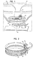
- FIG. 1 shows a vehicle steering device 10 with a steering wheel rim 12, spokes 14 and a hub 16, which is connected in a rotationally fixed manner to a steering column 18.
- the entirety of the non-rotatably coupled to the steering column 18 components is hereinafter referred to as steering wheel part.
- the steering device 10 also has a fixed relative to the rotatable steering wheel part central part, of which in Figure 1, only an upper sprocket 20 is shown.
- functional units are arranged, in particular a gas bag module, horn switch, function keys, etc.
- the double pinion member is supported in a skeleton portion of the steering apparatus 10 connected to the hub 16, more specifically, in a bottom portion of the skeleton.
- the upper pinion 26 and the lower pinion 28 of the Doppelritzelteils are with two similar circumferential sprockets 20 and 22, respectively.
- the lower ring gear 22 is fixed to the vehicle.
- the already mentioned upper sprocket 20 is part of the fixed middle part.
- the double pinion part Upon a rotational movement of the steering wheel part, the double pinion part is taken. Since the lower ring gear 22 is mounted fixed to the vehicle, the lower pinion 28 runs off on the lower ring gear 22. The rotation of the lower pinion 28 is transmitted to the upper pinion 26. Characterized the upper sprocket 20 and thus the entire central portion of the steering device 10 is rotated at the same speed opposite to the direction of rotation of the steering wheel part. Thus, the central part remains in its initial position and does not rotate with the steering wheel part.
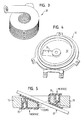
- a helically wound spring 30 is arranged, which is shown individually in FIG.
- the spring 30 serves as a carrier for the lines, which are required for the electrical connection of the functional units arranged on the central part.
- the axially elastic spring 30th has several turns of the same diameter, which have a generally rectangular cross-section.
- the upper end of the spring 30 is connected to the fixed center part of the steering device 10.
- the lower end of the spring 30 is fixed to the vehicle.
- the bottom 32 of the hub 16 has a passage opening 34 through which the spring 30 is performed.
- the bottom 32 of the hub 16 thus engages between two turns of the spring 30.
- the portion of the spring 30 between the hub bottom 32 and the middle part is either axially compressed or pulled apart, depending on the direction of rotation. The reverse is true for the portion of the spring 30 between the hub bottom 32 and the steering column.
- one or more plastic clips 36 may be inserted between the spring 30 and the hub 16 or spokes 14 of the steering device 10 to reduce friction between these components.
Abstract
Description
Die Erfindung betrifft eine Fahrzeuglenkvorrichtung, mit einem drehfest an eine Lenksäule gekoppelten Lenkradteil und einem gegenüber einer Drehung des Lenkradteils feststehenden Mittelteil, wobei eine Getriebeeinheit vorgesehen ist, die eine Drehung des Lenkradteils in einer ersten Richtung in eine entsprechende Drehung des Mittelteils in eine der ersten Richtung entgegengesetzten zweiten Richtung umsetzt.The invention relates to a vehicle steering device with a rotatably coupled to a steering column steering wheel part and a relation to a rotation of the steering wheel part fixed central part, wherein a transmission unit is provided, the rotation of the steering wheel part in a first direction in a corresponding rotation of the central part in one of the first direction converts opposite second direction.
Lenkvorrichtungen mit einem feststehenden Mittelteil haben grundsätzlich den Vorteil, daß am Mittelteil angeordnete Bedienelemente unabhängig von der Lenkradstellung immer an der gleichen Stelle zu finden sind. Bei Lenkvorrichtungen mit einem im feststehenden Mittelteil untergebrachten Gassackmodul muß der Gassack nicht mehr notwendigerweise symmetrisch zum Drehzentrum der Lenkvorrichtung gestaltet sein. Da die Orientierung des sich aus dem feststehenden Mittelteil entfaltenden Gassacks von vornherein feststeht, können asymmetrische Gassackformen mit optimierten Rückhalteeigenschaften eingesetzt werden. Sowohl die mechanische Realisierung der relativ zueinander drehbaren Baugruppen als auch die Verkabelung der am feststehenden Mittelteil angeordneten Komponenten erweisen sich jedoch als schwierig.Steering devices with a fixed center part have the advantage that arranged on the central part controls are always independent of the steering wheel position to find always in the same place. In steering devices with a gas bag module accommodated in the stationary central part, the gas bag no longer necessarily has to be designed symmetrically to the center of rotation of the steering device. Since the orientation of the gas bag deploying from the stationary middle part is fixed from the outset, asymmetric gas bag shapes with optimized retention properties can be used. However, both the mechanical realization of the relatively rotatable assemblies as well as the wiring of arranged on the fixed center part components prove to be difficult.
Aus der
Eine ähnliche Lösung, jedoch mit einem an den drehbaren Lenkradteil gekoppelten Getriebe, geht aus der gattungsbildenden
Die
Aufgabe der Erfindung ist es, eine Lenkvorrichtung mit feststehendem Mittelteil zu schaffen, das eine zuverlässige Relativdrehung zwischen dem Lenkradteil und dem Mittelteil sowie eine kostengünstige Verkabelung der am feststehenden Mittelteil angeordneten elektrischen Funktionseinheiten bietet.The object of the invention is to provide a steering device with a fixed central part, which provides a reliable relative rotation between the steering wheel part and the middle part and a cost-effective wiring of the fixed central part arranged electrical functional units.
Gemäß der Erfindung ist bei einer Fahrzeuglenkvorrichtung der eingangs genannten Art vorgesehen, daß sie ferner eine schraubenartig gewundene Feder umfaßt, die Leitungen zur elektrischen Anbindung von Funktionseinheiten trägt, welche am Mittelteil angeordnet sind. Grundlage der Erfindung ist die klare Trennung zwischen der Drehübertragung und der elektrischen Anbindung. Für die Übertragung der Drehung des Lenkradteils auf den Mittelteil in umgekehrter Richtung ist alleine die Getriebeeinheit zuständig, die eine robuste Übertragung der mechanischen Kräfte erlaubt und nur wenig Bauraum in Anspruch nimmt. Unabhängig davon erfolgt die elektrische Anbindung der Funktionseinheiten des Mittelteils, insbesondere eines Gassackmoduls, mit Hilfe der schraubenartig gewundenen Feder. Somit ist überhaupt keine Wickelfeder mehr erforderlich. Da die Feder keine mechanischen Kräfte übertragen muß, bestehen keine besonderen Anforderungen an deren Torsionssteifigkeit.According to the invention is provided in a vehicle steering device of the type mentioned in that it further comprises a helically wound spring carrying cables for electrical connection of functional units, which are arranged on the central part. The basis of the invention is the clear separation between the rotary transmission and the electrical connection. For the Transmission of the rotation of the steering wheel part on the central part in the reverse direction alone is the gear unit responsible, which allows a robust transmission of mechanical forces and takes up little space to complete. Regardless of the electrical connection of the functional units of the central part, in particular a gas bag module, using the helically wound spring. Thus, no coil spring is required at all. Since the spring does not have to transmit any mechanical forces, there are no special requirements for its torsional rigidity.
Gemäß einer bevorzugten Ausführungsform der Erfindung weist die Nabe der Fahrzeuglenkvorrichtung als Bestandteil des Lenkradteils eine Durchtrittsöffnung auf, durch die die Feder durchgeführt ist.According to a preferred embodiment of the invention, the hub of the vehicle steering device as part of the steering wheel part on a passage opening through which the spring is performed.
Die Erfindung wird nachfolgend unter Bezugnahme auf die beigefügten Zeichnungen näher beschrieben. In den Zeichnungen zeigen:
- Figur 1 eine erfindungsgemäße Fahrzeuglenkvorrichtung in perspektivischer Ansicht;
- Figur 2 den für die Relativdrehung verantwortlichen Teil der erfindungsgemäßen Lenkvorrichtung in perspektivischer Ansicht;
- Figur 3eine Schraubenfeder für die elektrische Anbindung in perspektivischer Ansicht;
- Figur 4 eine Nabe der erfindungsgemäßen Lenkvorrichtung in perspektivischer Ansicht; und
- Figur 5 eine schematische Schnittansicht durch einen Teil der erfindungsgemäßen Lenkvorrichtung.
- 1 shows a vehicle steering device according to the invention in a perspective view;
- Figure 2 shows the responsible for the relative rotation part of the steering device according to the invention in a perspective view;
- FIG. 3 shows a helical spring for the electrical connection in a perspective view;
- Figure 4 shows a hub of the steering device according to the invention in a perspective view; and
- Figure 5 is a schematic sectional view through part of the steering device according to the invention.
In Figur 1 ist eine Fahrzeuglenkvorrichtung 10 mit einem Lenkradkranz 12, Speichen 14 und einer Nabe 16 dargestellt, die drehfest mit einer Lenksäule 18 verbunden ist. Die Gesamtheit der drehfest an die Lenksäule 18 gekoppelten Bauteile wird im folgenden als Lenkradteil bezeichnet.1 shows a
Die Lenkvorrichtung 10 weist ferner einen gegenüber dem drehbaren Lenkradteil feststehenden Mittelteil auf, von dem in Figur 1 nur ein oberer Zahnkranz 20 gezeigt ist. Am Mittelteil sind Funktionseinheiten angeordnet, insbesondere ein Gassackmodul, Hupenschalter, Funktionstasten, etc.The
Damit der Mittelteil unabhängig von einer Drehung des Lenkradteils seine ortsfeste Position beibehält, ist eine Relativdrehung zwischen diesen beiden Baugruppen erforderlich. Die Relativdrehung wird durch eine spezielle Getriebeeinheit 24 mit einem Doppelritzelteil ermöglicht (siehe Figur 2). Eine solche Getriebeeinheit an sich ist aus der
Das Doppelritzelteil ist in einem mit der Nabe 16 verbundenen Skelettabschnitt der Lenkvorrichtung 10 gelagert, genauer gesagt in einem Bodenabschnitt des Skeletts. Das obere Ritzel 26 und das untere Ritzel 28 des Doppelritzelteils stehen mit zwei gleichartigen umlaufenden Zahnkränzen 20 bzw. 22 in Eingriff. Der untere Zahnkranz 22 ist fahrzeugfest gelagert. Der bereits erwähnte obere Zahnkranz 20 ist Bestandteil des feststehenden Mittelteils.The double pinion member is supported in a skeleton portion of the
Bei einer Drehbewegung des Lenkradteils wird das Doppelritzelteil mitgenommen. Da der untere Zahnkranz 22 fahrzeugfest gelagert ist, läuft das untere Ritzel 28 dabei auf dem unteren Zahnkranz 22 ab. Die Drehung des unteren Ritzels 28 wird auf das obere Ritzel 26 übertragen. Dadurch wird der obere Zahnkranz 20 und damit der gesamte Mittelteil der Lenkvorrichtung 10 mit gleicher Geschwindigkeit entgegengesetzt zur Drehrichtung des Lenkradteils gedreht. Somit bleibt der Mittelteil in seiner Ausgangsposition und dreht sich nicht mit dem Lenkradteil mit.Upon a rotational movement of the steering wheel part, the double pinion part is taken. Since the
Koaxial zur Lenksäule 18 ist eine schraubenartig gewundene Feder 30 angeordnet, die in Figur 3 einzeln gezeigt ist. Die Feder 30 dient als Träger für die Leitungen, die zur elektrischen Anbindung der am Mittelteil angeordneten Funktionseinheiten erforderlich sind. Die in axialer Richtung elastische Feder 30 weist mehrere Windungen mit gleichem Durchmesser auf, die einen allgemein rechteckförmigen Querschnitt haben.Coaxially to the
Das obere Ende der Feder 30 ist mit dem feststehenden Mittelteil der Lenkvorrichtung 10 verbunden. Das untere Ende der Feder 30 ist fahrzeugfest fixiert. Wie in Figur 4 zu erkennen ist, weist der Boden 32 der Nabe 16 eine Durchtrittsöffnung 34 auf, durch die die Feder 30 durchgeführt ist. Der Boden 32 der Nabe 16 greift somit zwischen zwei Windungen der Feder 30 ein. Bei einer Drehung des Lenkradteils wird der Abschnitt der Feder 30 zwischen dem Nabenboden 32 und dem Mittelteil abhängig von der Drehrichtung entweder axial gestaucht oder auseinandergezogen. Das umgekehrte gilt jeweils für den Abschnitt der Feder 30 zwischen dem Nabenboden 32 und dem Lenkstock.The upper end of the
Wie in Figur 5 gezeigt, können ein oder mehrere Kunststoffclips 36, insbesondere Teflonchips, zwischen der Feder 30 und der Nabe 16 bzw. den Speichen 14 der Lenkvorrichtung 10 eingesetzt werden, um die Reibung zwischen diesen Komponenten zu reduzieren.As shown in Figure 5, one or more
Claims (6)
Applications Claiming Priority (1)
| Application Number | Priority Date | Filing Date | Title |
|---|---|---|---|
| DE200520003848 DE202005003848U1 (en) | 2005-03-10 | 2005-03-10 | Vehicle steering device with fixed central part |
Publications (1)
| Publication Number | Publication Date |
|---|---|
| EP1700771A2 true EP1700771A2 (en) | 2006-09-13 |
Family
ID=34716927
Family Applications (1)
| Application Number | Title | Priority Date | Filing Date |
|---|---|---|---|
| EP06004108A Withdrawn EP1700771A2 (en) | 2005-03-10 | 2006-03-01 | Steering device with non-rotating central hub |
Country Status (3)
| Country | Link |
|---|---|
| US (1) | US20060213315A1 (en) |
| EP (1) | EP1700771A2 (en) |
| DE (1) | DE202005003848U1 (en) |
Cited By (1)
| Publication number | Priority date | Publication date | Assignee | Title |
|---|---|---|---|---|
| DE102007044797A1 (en) | 2007-09-19 | 2009-04-02 | Still Gmbh | Steering device for trucks, has steering wheel with fixed operating or display element which is arranged on fixed standing column, where steering wheel remains in operative connection with rotating steering column |
Families Citing this family (9)
| Publication number | Priority date | Publication date | Assignee | Title |
|---|---|---|---|---|
| DE502005001173D1 (en) * | 2004-03-01 | 2007-09-20 | Takata Petri Ag | DEVICE FOR STORING A MODULE ON THE STEERING WHEEL OF A MOTOR VEHICLE |
| WO2005100128A1 (en) * | 2004-04-13 | 2005-10-27 | Dalphimetal España, S.A. | Motor vehicle steering wheel comprising a fixed module |
| EP1707469A1 (en) * | 2005-04-01 | 2006-10-04 | Key Safety Systems, Inc. | Steering wheel with stationary hub mounted portion |
| FR2891884A1 (en) * | 2005-10-12 | 2007-04-13 | Peugeot Citroen Automobiles Sa | Coil spring for integration of flywheel`s fixed hub in motor vehicle, has sheath maintaining radial spaces between turns of cores so that cores are electrically isolated from one another, where turns have sections with reduced side lengths |
| US20100175499A1 (en) * | 2009-01-09 | 2010-07-15 | Ford Global Technologies, Llc | Vehicle steering wheel assembly |
| WO2016051776A1 (en) * | 2014-10-03 | 2016-04-07 | アダマンド株式会社 | Steering-wheel power generation device |
| ITUA20164342A1 (en) * | 2016-06-14 | 2017-12-14 | I F R A S R L | APPARATUS FOR CHANGING THE DIRECTION OF ADVANCEMENT OF A VEHICLE, IN PARTICULAR OF A NAUTICAL VEHICLE. |
| US11407436B2 (en) * | 2019-03-04 | 2022-08-09 | Byton North America Corporation | Steering wheel with fixed center |
| US11708104B2 (en) * | 2020-02-19 | 2023-07-25 | Kuster North America, Inc. | Steering wheel mounted display assembly retaining upright orientation regardless of rotated position |
Citations (3)
| Publication number | Priority date | Publication date | Assignee | Title |
|---|---|---|---|---|
| DE3621226C1 (en) | 1986-06-25 | 1988-01-14 | Daimler Benz Ag | Steering wheel arrangement for vehicles |
| EP1323617B1 (en) | 2001-12-20 | 2004-07-14 | Peugeot Citroen Automobiles SA | Steering assembly for a motor vehicle |
| DE202004007617U1 (en) | 2003-07-22 | 2004-12-09 | Trw Automotive Safety Systems Gmbh | Vehicle steering device, has steering wheel part coupled to steering column, and central part that is stationary with regard to rotation of wheel part, and supply line passed along hub that is sited out from device and clock spring |
Family Cites Families (5)
| Publication number | Priority date | Publication date | Assignee | Title |
|---|---|---|---|---|
| US3525536A (en) * | 1968-10-11 | 1970-08-25 | Eaton Yale & Towne | Vehicle safety apparatus positioned on steering wheel |
| DE3111922C1 (en) * | 1981-03-26 | 1982-11-11 | Daimler-Benz Ag, 7000 Stuttgart | Power line connector for rotatable components |
| JPS57172879A (en) * | 1981-04-14 | 1982-10-23 | Aisin Seiki Co Ltd | Steering handle for automobile |
| JPS5993950U (en) * | 1983-02-25 | 1984-06-26 | 豊田合成株式会社 | Steering wheel cable storage structure |
| US7290789B2 (en) * | 2003-07-22 | 2007-11-06 | Trw Automotive Safety Systems Gmbh | Vehicle steering device with stationary central part |
-
2005
- 2005-03-10 DE DE200520003848 patent/DE202005003848U1/en not_active Expired - Lifetime
-
2006
- 2006-03-01 EP EP06004108A patent/EP1700771A2/en not_active Withdrawn
- 2006-03-10 US US11/372,543 patent/US20060213315A1/en not_active Abandoned
Patent Citations (3)
| Publication number | Priority date | Publication date | Assignee | Title |
|---|---|---|---|---|
| DE3621226C1 (en) | 1986-06-25 | 1988-01-14 | Daimler Benz Ag | Steering wheel arrangement for vehicles |
| EP1323617B1 (en) | 2001-12-20 | 2004-07-14 | Peugeot Citroen Automobiles SA | Steering assembly for a motor vehicle |
| DE202004007617U1 (en) | 2003-07-22 | 2004-12-09 | Trw Automotive Safety Systems Gmbh | Vehicle steering device, has steering wheel part coupled to steering column, and central part that is stationary with regard to rotation of wheel part, and supply line passed along hub that is sited out from device and clock spring |
Cited By (1)
| Publication number | Priority date | Publication date | Assignee | Title |
|---|---|---|---|---|
| DE102007044797A1 (en) | 2007-09-19 | 2009-04-02 | Still Gmbh | Steering device for trucks, has steering wheel with fixed operating or display element which is arranged on fixed standing column, where steering wheel remains in operative connection with rotating steering column |
Also Published As
| Publication number | Publication date |
|---|---|
| DE202005003848U1 (en) | 2005-06-30 |
| US20060213315A1 (en) | 2006-09-28 |
Similar Documents
| Publication | Publication Date | Title |
|---|---|---|
| EP1700771A2 (en) | Steering device with non-rotating central hub | |
| DE3406327A1 (en) | STEERING WHEEL DEVICE FOR VEHICLES | |
| EP1013534B1 (en) | Electrical power steering especially for motor vehicles | |
| EP2875327A2 (en) | Device with a torque sensor unit and optionally a steering angle sensor unit for a motor vehicle and method for assembling such a device from a plurality of components | |
| EP2084352B1 (en) | Motor vehicle door lock | |
| EP2064465B1 (en) | Transmission device | |
| EP1632320B1 (en) | Robot wrist with hose drive for rotating a supply hose, and associated process | |
| WO2020165240A1 (en) | Drive device for an electric bike comprising a rotor shaft of an electric motor that can rotate about a fourth shaft axis | |
| EP2038161A2 (en) | Steering device and operating method for it | |
| EP1199500B1 (en) | Shift actuator of a gearbox | |
| DE102018131933A1 (en) | Door drive device | |
| EP1641656B1 (en) | Device for mounting a module on the steering wheel of a motor vehicle | |
| DE3443625C2 (en) | ||
| WO2014044277A1 (en) | Gear assembly | |
| DE4235055A1 (en) | Housing for a contact spiral | |
| EP0642834A2 (en) | Locking device for a bearing arrangement especially for the separating chamber of a centrifuge | |
| DE102009031214A1 (en) | Axle transmission for use in electric vehicle, has electrical machine provided to drive differential gear, where electrical machine is coupled by two planetary gears with differential basket of differential gear | |
| DE102007005148A1 (en) | Angle superimposition gear unit for active guidance of vehicle, has input shaft connected with steering wheel of vehicle and output shaft connected with steering wheel of vehicle and gear | |
| EP1249389A2 (en) | Actuating mechanism for a multispeed hub shifter | |
| DE102004047393A1 (en) | The blind assembly | |
| DE4328563C1 (en) | Steering wheel arrangement with a hub cushion which is stationary in relation to the steering wheel | |
| DE102008016970B3 (en) | Steering device for a motor vehicle with a steering wheel and a superposition gear | |
| WO2006081813A1 (en) | Steering mechanism with an airbag arrangement and operational method therefor | |
| WO2006136221A1 (en) | Roof antenna with a worm gearing for fastening the antenna | |
| DE102006013288A1 (en) | Superposition device for use in vehicle steering system, has superposition gear that is designed as single-stage worm wheel gear with worm wheel driven by worm shaft, and pivotably supported against wheel in area of worm shaft ends |
Legal Events
| Date | Code | Title | Description |
|---|---|---|---|
| PUAI | Public reference made under article 153(3) epc to a published international application that has entered the european phase |
Free format text: ORIGINAL CODE: 0009012 |
|
| AK | Designated contracting states |
Kind code of ref document: A2 Designated state(s): AT BE BG CH CY CZ DE DK EE ES FI FR GB GR HU IE IS IT LI LT LU LV MC NL PL PT RO SE SI SK TR |
|
| AX | Request for extension of the european patent |
Extension state: AL BA HR MK YU |
|
| STAA | Information on the status of an ep patent application or granted ep patent |
Free format text: STATUS: THE APPLICATION IS DEEMED TO BE WITHDRAWN |
|
| 18D | Application deemed to be withdrawn |
Effective date: 20101001 |