EP0809469B1 - Automatic suturing and ligating device - Google Patents
Automatic suturing and ligating device Download PDFInfo
- Publication number
- EP0809469B1 EP0809469B1 EP95912561A EP95912561A EP0809469B1 EP 0809469 B1 EP0809469 B1 EP 0809469B1 EP 95912561 A EP95912561 A EP 95912561A EP 95912561 A EP95912561 A EP 95912561A EP 0809469 B1 EP0809469 B1 EP 0809469B1
- Authority
- EP
- European Patent Office
- Prior art keywords
- ligature
- suture thread
- tissue
- vessel
- duct
- Prior art date
- Legal status (The legal status is an assumption and is not a legal conclusion. Google has not performed a legal analysis and makes no representation as to the accuracy of the status listed.)
- Expired - Lifetime
Links
- 238000003466 welding Methods 0.000 claims description 23
- 230000007246 mechanism Effects 0.000 claims description 16
- 238000005520 cutting process Methods 0.000 claims description 8
- 230000009471 action Effects 0.000 claims description 3
- 241001465754 Metazoa Species 0.000 claims description 2
- 230000003213 activating effect Effects 0.000 claims description 2
- 230000004913 activation Effects 0.000 claims description 2
- 230000009977 dual effect Effects 0.000 claims description 2
- 238000001035 drying Methods 0.000 claims 1
- 239000003356 suture material Substances 0.000 abstract description 37
- 238000000034 method Methods 0.000 abstract description 13
- 239000000155 melt Substances 0.000 abstract description 2
- 210000001519 tissue Anatomy 0.000 description 46
- 206010052428 Wound Diseases 0.000 description 30
- 208000027418 Wounds and injury Diseases 0.000 description 30
- 239000000463 material Substances 0.000 description 9
- 230000008569 process Effects 0.000 description 6
- 230000001681 protective effect Effects 0.000 description 4
- 238000005304 joining Methods 0.000 description 3
- CURLTUGMZLYLDI-UHFFFAOYSA-N Carbon dioxide Chemical compound O=C=O CURLTUGMZLYLDI-UHFFFAOYSA-N 0.000 description 2
- 230000008901 benefit Effects 0.000 description 2
- 238000010438 heat treatment Methods 0.000 description 2
- 208000014674 injury Diseases 0.000 description 2
- 210000002435 tendon Anatomy 0.000 description 2
- 230000008733 trauma Effects 0.000 description 2
- 210000001367 artery Anatomy 0.000 description 1
- 210000000013 bile duct Anatomy 0.000 description 1
- 239000008280 blood Substances 0.000 description 1
- 210000004369 blood Anatomy 0.000 description 1
- 210000004204 blood vessel Anatomy 0.000 description 1
- 229910002092 carbon dioxide Inorganic materials 0.000 description 1
- 239000001569 carbon dioxide Substances 0.000 description 1
- 210000000845 cartilage Anatomy 0.000 description 1
- 230000000295 complement effect Effects 0.000 description 1
- 238000002674 endoscopic surgery Methods 0.000 description 1
- 208000015181 infectious disease Diseases 0.000 description 1
- 239000002085 irritant Substances 0.000 description 1
- 231100000021 irritant Toxicity 0.000 description 1
- 210000003041 ligament Anatomy 0.000 description 1
- 238000002324 minimally invasive surgery Methods 0.000 description 1
- 239000012768 molten material Substances 0.000 description 1
- 230000000149 penetrating effect Effects 0.000 description 1
- 229920000642 polymer Polymers 0.000 description 1
- 238000010926 purge Methods 0.000 description 1
- 230000008439 repair process Effects 0.000 description 1
- 230000037390 scarring Effects 0.000 description 1
- 238000010008 shearing Methods 0.000 description 1
- 238000001356 surgical procedure Methods 0.000 description 1
- 210000003462 vein Anatomy 0.000 description 1
- 210000001835 viscera Anatomy 0.000 description 1
- 238000011179 visual inspection Methods 0.000 description 1
Images


Classifications
-
- A—HUMAN NECESSITIES
- A61—MEDICAL OR VETERINARY SCIENCE; HYGIENE
- A61B—DIAGNOSIS; SURGERY; IDENTIFICATION
- A61B17/00—Surgical instruments, devices or methods
- A61B17/12—Surgical instruments, devices or methods for ligaturing or otherwise compressing tubular parts of the body, e.g. blood vessels or umbilical cord
- A61B17/12009—Implements for ligaturing other than by clamps or clips, e.g. using a loop with a slip knot
- A61B17/12013—Implements for ligaturing other than by clamps or clips, e.g. using a loop with a slip knot for use in minimally invasive surgery, e.g. endoscopic surgery
-
- A—HUMAN NECESSITIES
- A61—MEDICAL OR VETERINARY SCIENCE; HYGIENE
- A61B—DIAGNOSIS; SURGERY; IDENTIFICATION
- A61B17/00—Surgical instruments, devices or methods
- A61B17/04—Surgical instruments, devices or methods for suturing wounds; Holders or packages for needles or suture materials
- A61B17/0469—Suturing instruments for use in minimally invasive surgery, e.g. endoscopic surgery
-
- A—HUMAN NECESSITIES
- A61—MEDICAL OR VETERINARY SCIENCE; HYGIENE
- A61B—DIAGNOSIS; SURGERY; IDENTIFICATION
- A61B17/00—Surgical instruments, devices or methods
- A61B17/04—Surgical instruments, devices or methods for suturing wounds; Holders or packages for needles or suture materials
- A61B17/0467—Instruments for cutting sutures
-
- A—HUMAN NECESSITIES
- A61—MEDICAL OR VETERINARY SCIENCE; HYGIENE
- A61B—DIAGNOSIS; SURGERY; IDENTIFICATION
- A61B17/00—Surgical instruments, devices or methods
- A61B17/04—Surgical instruments, devices or methods for suturing wounds; Holders or packages for needles or suture materials
- A61B17/0482—Needle or suture guides
-
- A—HUMAN NECESSITIES
- A61—MEDICAL OR VETERINARY SCIENCE; HYGIENE
- A61B—DIAGNOSIS; SURGERY; IDENTIFICATION
- A61B17/00—Surgical instruments, devices or methods
- A61B17/04—Surgical instruments, devices or methods for suturing wounds; Holders or packages for needles or suture materials
- A61B17/06—Needles ; Sutures; Needle-suture combinations; Holders or packages for needles or suture materials
- A61B17/06066—Needles, e.g. needle tip configurations
-
- A—HUMAN NECESSITIES
- A61—MEDICAL OR VETERINARY SCIENCE; HYGIENE
- A61B—DIAGNOSIS; SURGERY; IDENTIFICATION
- A61B17/00—Surgical instruments, devices or methods
- A61B17/04—Surgical instruments, devices or methods for suturing wounds; Holders or packages for needles or suture materials
- A61B17/0469—Suturing instruments for use in minimally invasive surgery, e.g. endoscopic surgery
- A61B2017/0472—Multiple-needled, e.g. double-needled, instruments
-
- A—HUMAN NECESSITIES
- A61—MEDICAL OR VETERINARY SCIENCE; HYGIENE
- A61B—DIAGNOSIS; SURGERY; IDENTIFICATION
- A61B17/00—Surgical instruments, devices or methods
- A61B17/04—Surgical instruments, devices or methods for suturing wounds; Holders or packages for needles or suture materials
- A61B17/06—Needles ; Sutures; Needle-suture combinations; Holders or packages for needles or suture materials
- A61B2017/06052—Needle-suture combinations in which a suture is extending inside a hollow tubular needle, e.g. over the entire length of the needle
-
- A—HUMAN NECESSITIES
- A61—MEDICAL OR VETERINARY SCIENCE; HYGIENE
- A61B—DIAGNOSIS; SURGERY; IDENTIFICATION
- A61B17/00—Surgical instruments, devices or methods
- A61B17/04—Surgical instruments, devices or methods for suturing wounds; Holders or packages for needles or suture materials
- A61B17/06—Needles ; Sutures; Needle-suture combinations; Holders or packages for needles or suture materials
- A61B17/06166—Sutures
- A61B2017/06185—Sutures hollow or tubular
-
- A—HUMAN NECESSITIES
- A61—MEDICAL OR VETERINARY SCIENCE; HYGIENE
- A61B—DIAGNOSIS; SURGERY; IDENTIFICATION
- A61B17/00—Surgical instruments, devices or methods
- A61B17/04—Surgical instruments, devices or methods for suturing wounds; Holders or packages for needles or suture materials
- A61B17/06—Needles ; Sutures; Needle-suture combinations; Holders or packages for needles or suture materials
- A61B17/06166—Sutures
- A61B2017/0619—Sutures thermoplastic, e.g. for bonding, welding, fusing or cutting the suture by melting it
Definitions
- the present invention relates generally to closing or joining openings and wounds and tying off of vessels and ducts in human and animal tissue, and more particularly to suturing and ligating devices for closing wounds and vessels, respectively, including hand held devices with specific application and utility in hard to reach and internal suturing and ligating needs.
- a curved needle with a thread attached is typically held by forceps, with which a surgeon or nurse forces the needle through the tissue on one side of a wound and, following the curve of the needle, across the opening and up through the tissue on the opposite side of the wound.
- the user releases the forceps' hold on the needle and with the forceps re-grasps a portion of the protruding needle.
- the needle is pulled through with the thread following along.
- the thread is manually drawn tight, knotted and cut. This process is repeated to form multiple stitches (stitch and suture are herein defined as equivalents) until the wound is closed.
- anatomical vessels e.g. blood arteries and veins, etc.
- ducts e.g. bile ducts, etc.
- a previously knotted thread is passed over the end of a vessel, tightened to occlude the vessel, and the loose ends of the thread are snipped off. If the vessel or duct passes through a surgical site with no end accessible, the suture thread is passed around the vessel, knotted externally, tightened and the loose ends cut.
- the needle bends into the arcuate shape as it extends from the tube and so penetrates the tissue, arcing down then across the wound opening and finally up on the opposite side of the wound where the needle protrudes.
- an elongated forceps is inserted which grasps the protruding portion of the needle and pulls the needle through with the thread trailing.
- the thread is knotted completing the stitch.
- This device is designed for hard to reach areas where there is not enough room for manual suturing techniques. However the need to re-grasp the needle to complete the stitch, the difficulty of tying remotely through the tube are limitations remaining with this device.
- An object of this invention is to overcome the above illustrated limitations and problems by providing means to perform suturing which penetrates tissue leaving a thread, to perform ligating which surrounds vessels or ducts with a thread, to draw the thread taut closing the wound or occluding the vessel, and then to cut and secure the thread in a reliable repeatable manner.
- Another object of this invention is the ability to introduce a gas into the opening which distends the cavity for visual inspection during endoscopic surgery, and to purge the joining area to ensure a reliable joint.
- US-A-4 935 027 discloses a device which allows a surgeon to introduce a suture strand into and through tissue to be repaired.
- the device includes complementary channelled structures with tissue-penetrating tips. The tips penetrate tissue and then mate to form a continuous suture channel through which the suture strand passes unobstructedly. Once the suture strand has been passed through the tissue to be repaired, the device can be removed. The suture extending from the tissue can then be knotted, and a pushing instrument advances the knot toward the repair site.
- the present invention provides an automatic device for ligating a vessel or duct for suturing tissue and more particularly suitable for forming a completed suture or ligature, respectively, without repositioning the device, said device including a housing having proximal and distal ends, said distal end being adapted to be placed adjacent a suturing location in tissue or a ligating location around a vessel or duct, means for puncturing said tissue or for surrounding said vessel or duct, provided at said distal end of said housing and configured to form a passage through said tissue or around said vessel or duct, through which suture thread or ligature can be threaded, said passage communicating with at least one opening through said housing and the device having means for threading said suture thread or ligature, said threading means being constructed in the distal end of said housing where said suture thread or ligature is aligned with and proximate to said passage opening, the device being characterized by means for tightening and clamping said suture thread or ligature
- the present suturing and ligating structure or device utilizes, in a preferred embodiment, a needle that is constructed with a channel suitable for accommodating suture material.
- needle is defined as a device which establishes a channel through tissue or around vessels and ducts suitable for passing suture material, and suture material and suture thread or ligature are synonymous herein.
- the channel may be a hollow needle or a U-shaped channel.
- For suturing the needle penetrates the tissue on one side of the wound travelling below the wound and emerges from the opposite side of the wound.
- For ligating the needle surrounds the vessel or duct.
- the needle may be constructed to draw the wound, vessel or duct together as the needle penetrates the tissue or surrounds the vessel or duct.
- the wound, vessel or duct may be closed by tightening the suture material.
- suture material is threaded through the channel and secured.
- the needle is removed leaving the suture material.
- the suture material is drawn and secured at a given tension, cut and the ends welded together whereupon the device is removed.
- the cutting may be done as a separate hand operation, say by scissors, after the device is removed.
- the suturing objects are also met by puncturing said tissue wherein a passage is created through the tissue.
- Suture thread is passed through said passage, tightened and joined forming a completed suture.
- the suture material is joined to the puncturing needle and trails the needle as the needle passes through the tissue. When the needle leaves the tissue the suture material remains in place.
- the suture material, extending from each side of the wound, is tightened, cut and joined by welding.
- the passage is defined as a way through the tissue without any needle or other artificial or foreign device remaining in the tissue.
- the device comprises two curved, opposed needles.
- the needles penetrate the tissue on either side of the wound meeting within the tissue below the wound. In ligating, however, the needles surround the vessel or duct with the needles meeting opposite the device. As the needles come together the wound, vessel or duct is closed.
- These needles are each formed with cross sections that have U-shaped channels, and when the needles meet a continuous U-shaped channel is provided through the tissue or around the vessel or duct.
- the suture material is threaded through the U-shaped channel and secured, allowing the needles to be retracted.
- the suture material is drawn taut to a given tension, cut and ultrasonically welded.
- the device is removed leaving a completed stitch.
- FIG. 1A shows a side view of a preferred embodiment 10 of the invention.
- a handle 12 houses a spool (not shown) of suture material, a battery, ultrasonic signal generating equipment and a controller.
- a spool (not shown) of suture material
- a battery e.g., a battery
- ultrasonic signal generating equipment e.g., a battery
- FIG. 1B shows a side view of the device 10 with the protective sheath retracted exposing tip 16 at the end of the shaft 13.
- the protective sheath 14 slides over and protects the tip 16 during handling and positioning of the device. The tip 16 is exposed when the device is in position and ready to create a stitch.
- the handle 12 includes a multi-function trigger mechanism 15 which may, in other preferred embodiments, activate some of the processes described hereinafter.
- Alternative preferred embodiments include several activating triggers, switches and/or levers.
- Another preferred embodiment comprises a supply of gas, preferably carbon dioxide, communicating with the tip 16 through hollow passages, and with a control valve at the handle.
- gas preferably carbon dioxide
- This arrangement allows, at the operator's option, a steady introduction of gas onto the area of surgery to distend a cavity for endoscopic viewing, per currently accepted surgical practice.
- a burst of gas may be used to dry the weld area.
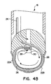
- FIGs 2 and 3A show the tip 16 in contact with tissue 18, straddling a wound to be stitched closed.
- left and right hand curved needles, 22A and 22B, respectively are rotated about pivot 23 penetrating the tissue 18, partially closing the wound 20, as in FIG. 3A.
- the needles 22 meet below the tissue surface and engage each other forming a continuous channel through the tissue traversing the wound 20.
- Another preferred embodiment (not shown) comprises a single needle rotated through the tissue around the wound from one side.
- Another preferred embodiment comprises a needle or dual needles utilizing a moving pivot.
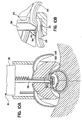
- FIG. 3B and FIG. 3D shows the cross section of each side of the needles 22, as the needles appear when inserted into the tissue.
- FIG. 3C shows the overlapping region of the needles 22 showing the right hand needle 22B nested inside the left hand needle 22A. As shown, the needles 22 form a continuous uninterrupted channel through the tissue, and this channel is sufficient for a suture thread to be inserted through the channel.
- the needles are activated via linkages or a worm gear, joined to the proximate end of each needle, running down the shaft or by other known alternative mechanisms.
- Driving means wherein said linkage is activated, drives said needles into the tissue.
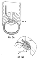
- FIGs. 4A, 4B, 5A, 5B show the suture material being threaded through the channel 24 until its path is blocked by a stop 28 on weld anvil 30. In other preferred embodiments the exact length of thread is advanced eliminating the need of the stop 28.
- the threading mechanism, in the housing 12 or the shaft 13, is known in the art.
- FIG. 5B the weld anvil moves in the direction of the arrow 32.
- a vertically extending member 34 of the anvil 30 is forced against the suture material 26, clamping and securing the material against a wall (not shown) of the tip 16.
- a vertical rod may be used to clamp the material 26 or forceps-like mechanism may grasp the material 26.
- FIG. 6 depicts the result after the needles 2 are withdrawn, leaving the suture thread 26 threaded through the tissue 18 and secured at the anvil 30.
- FIG. 7 shows the thread 26 drawn taut until a desired, preset tension level is achieved, for fully closing the wound 20.
- the material is tightened by a mechanism within the housing 12.
- a mechanism may be a drive system to rewind the spool or a mechanical collar to tighten onto the material and draw the material taut.
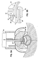
- FIG. 8A shows a spring loaded clamp 25 which, when activated, forces the suture thread 26 against the anvil 30.
- FIG. 8B show in detail where the clamp 25 comes down firmly holding the suture material 26 against the anvil surface 33. Operation of the clamp 25 is accomplished by linear advancement of the ultrasonic welding mechanism (not shown) to which the clamp 25 is attached via the spring 27. In another preferred embodiment the clamp 25 is activated by using known means, either manual or automatic via the controller. Still referring to FIG. 8B the needles 22 are withdrawn from the tissue, the suture material is taut and held at both ends with an overlap 34.
- FIG. 9A shows an ultrasonic welding mechanism. This mechanism has a piezoelectric stack 36 coupled with a tuned ultrasonic weld horn 38 extending towards the anvil 30.
- the suture material is cut by advancing the horn 38 along the shaft 13 until the horn edge 39 shears the material against a sharp protrusion 41 on the anvil.
- Other manual or automatic shearing mechanisms known in the art may be alternatively used.
- Activation of the piezoelectric stack accomplishes the welding of the suture material, and the stack 36 may be activated before, after or during the advancement of the horn which cuts the material.
- the ultrasonically vibrating welding horn 38 continues advancing toward the tip 16 compressing the overlying suture material 26 against the underlying suture material in the overlapping region 34.
- Ultrasonic energy transferred through the horn 38 melts the suture material 26 in the overlapping region 34.
- the controller e.g. a microprocessor, a computer and program or the like, regulates the energy imparted to the suture material to produce an optimum weld.
- the piezoelectric stack is then deactivated.
- Other preferred embodiments employ magnetostrictive apparatuses or other known ultrasonic drivers in place of the piezoelectric stack as an ultrasonic energy source to join (weld) the suture material.
- Still other preferred embodiments employ heating mechanisms such as resistance heating elements or laser sources in place of the ultrasonic welding mechanism to join or cut and join the ends of the suture material loop.
- the energy required to join the suture material ends and the time to permit resolidification of the molten suture material is well known in the art for different suture materials, e.g., polymer monofilament, and for the various threads sizes available.
- Both the horn 38, at the weld site, and the spring loaded clamp 25 stay in contact with the suture material maintaining the clamping action for a predetermined (known) time period allowing the molten suture material to re-solidify, thereby completing the weld.
- the horn 38, the vertically extending member 34 and the spring loaded clamp 25 stay in contact with the suture material for the known time period required for the molten material to re-solidify completing the stitch.
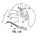
- FIG. 11A shows the weld anvil 30 being retracted (in the direction of the arrow 45 in FIG. 11B) releasing the completed stitch.
- the device 10 may now be completely withdrawn.
- the enlarged view of FIG. 11B shows the cut suture end 42 ready to be threaded through the needles for the next stitch, the knot-less weld 46, and the anvil 30 retracted in the direction of the arrow.
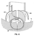
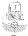
- FIG. 12 shows the tip 16 positioned proximate the vessel or duct 48 to be ligated.
- FIG. 13 shows the needles 22 rotated about the pivot 23 such that they engage, forming a continuous channel around the vessel or duct 48.
- the suture thread is then advanced as shown in FIG. 4A and 4B.
- the distal end of the thread is then clamped as shown in FIG. 5A and 5B.
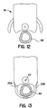
- FIG. 14 shows the needles 22 retracted in the same manner as shown in FIG. 6, leaving a loop of suture thread 26 around the vessel or duct 48.
- FIG. 15 shows the tightened suture thread occluding the vessel or duct 48 to be ligated.
- the proximate portion of the thread is then clamped as shown in FIG. 8A and 8B, cut as shown in FIG. 9A and 9B, and welded as shown in FIG. 10A and 10B.
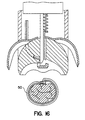
- FIG. 16 shows the completed ligating stitch 50 and the occluded vessel or duct 48 (in section).
Landscapes
- Health & Medical Sciences (AREA)
- Surgery (AREA)
- Life Sciences & Earth Sciences (AREA)
- Heart & Thoracic Surgery (AREA)
- Molecular Biology (AREA)
- Veterinary Medicine (AREA)
- Engineering & Computer Science (AREA)
- Biomedical Technology (AREA)
- Public Health (AREA)
- Medical Informatics (AREA)
- Nuclear Medicine, Radiotherapy & Molecular Imaging (AREA)
- Animal Behavior & Ethology (AREA)
- General Health & Medical Sciences (AREA)
- Reproductive Health (AREA)
- Vascular Medicine (AREA)
- Surgical Instruments (AREA)
- Sewing Machines And Sewing (AREA)
- Vending Machines For Individual Products (AREA)
Abstract
Description
- The present invention relates generally to closing or joining openings and wounds and tying off of vessels and ducts in human and animal tissue, and more particularly to suturing and ligating devices for closing wounds and vessels, respectively, including hand held devices with specific application and utility in hard to reach and internal suturing and ligating needs.
- Suturing or closing of wounds is still dominated by hand stitching methods. A curved needle with a thread attached is typically held by forceps, with which a surgeon or nurse forces the needle through the tissue on one side of a wound and, following the curve of the needle, across the opening and up through the tissue on the opposite side of the wound. The user releases the forceps' hold on the needle and with the forceps re-grasps a portion of the protruding needle. The needle is pulled through with the thread following along. The thread is manually drawn tight, knotted and cut. This process is repeated to form multiple stitches (stitch and suture are herein defined as equivalents) until the wound is closed.
- Similarly, hand methods of ligating or tying off anatomical vessels (e.g. blood arteries and veins, etc.) and ducts (e.g. bile ducts, etc.) still dominate this art. A previously knotted thread is passed over the end of a vessel, tightened to occlude the vessel, and the loose ends of the thread are snipped off. If the vessel or duct passes through a surgical site with no end accessible, the suture thread is passed around the vessel, knotted externally, tightened and the loose ends cut.
- Although the forgoing process is easily accomplished on wounds with easy access and room to work, in areas of limited access the required manipulation of the forceps may be impossible. This is especially true of internal wounds, for example to internal organs, tendons, cartilage, etc. Here a large opening in the external skin, with the attendant trauma and morbidity, is made providing room to suture. In addition the knots of the tied sutures are irritants and may become lodged in the tissue creating difficult removal of the stitches.
- Other limitations stem from the manual nature of the stitches. The force used, the depth of the stitch, the tautness of the resulting stitch and the knotting may vary significantly resulting in areas of infection, discomfort and scarring.
- There have been attempts to improve suturing. U.S. patent no. 5,037,433 titled "Endoscopic Suturing Device and Related Method and Suture", issued to Peter J. Wilk et al. on August 6, 1991 discloses one such attempt. Wilk et al. teach an elongated, flexible tube containing a smaller tube. This smaller tube contains a spring needle, forced straight while in the tube, but which, if unrestrained, would form an arcuate shape. A thread is attached to the needle. The smaller tube is placed adjacent to a wound opening and the spring needle slides out from the smaller tube. The needle bends into the arcuate shape as it extends from the tube and so penetrates the tissue, arcing down then across the wound opening and finally up on the opposite side of the wound where the needle protrudes. Through the outer flexible tube, an elongated forceps is inserted which grasps the protruding portion of the needle and pulls the needle through with the thread trailing. The thread is knotted completing the stitch. This device is designed for hard to reach areas where there is not enough room for manual suturing techniques. However the need to re-grasp the needle to complete the stitch, the difficulty of tying remotely through the tube are limitations remaining with this device.
- Other devices are known in the art wherein a suture or suture like needle is mechanically forced through tissue closing the wound.
- Another device is described U.S. patent no. 3,638,653 titled "Suturing Device", issued to H. Lee Berry on Feb. 1, 1972, discloses a hollow suturing needle through which a thread is drawn.
- These foregoing devices mechanically force the needle through the tissue and presumably do so in a consistent, repeatable manner, but the devices are cumbersome and most use the standard suture or a very similar needle. These devices share common problems. The attachment of the needle to the thread and the ability to remove the needle while leaving the thread are common problems with these devices. The drawing, cutting and tying of the thread remain to be done manually or with another instrument. The manual processes entail problems of tautness, knotting and other inconsistencies.
- An object of this invention is to overcome the above illustrated limitations and problems by providing means to perform suturing which penetrates tissue leaving a thread, to perform ligating which surrounds vessels or ducts with a thread, to draw the thread taut closing the wound or occluding the vessel, and then to cut and secure the thread in a reliable repeatable manner.
- It is a another object to perform suturing with one device which completes the stitching in one operation.
- It is a further object of this invention to complete the stitch without a knot. This removes an area of discomfort and difficulties if the knot becomes buried in the tissue, further to use materials which need not be removed but are absorbed by the host tissue.
- It is yet another object of this invention to provide an instrument well suited to perform suturing and ligating in areas of limited access, such as arthroscopic, laparoscopic and other endoscopic assisted procedures, wherein the suture is completed with an opening in the tissue which is minor as compared to openings usually associated with such procedures.
- It is yet another object to limit the trauma and morbidity generally associated with internal suturing, by requiring only a small opening in the external tissue.
- It is another object of the invention to provide a suturing device well suited to grafting, closing off blood vessels and other minimally invasive procedures.
- Another object of this invention is the ability to introduce a gas into the opening which distends the cavity for visual inspection during endoscopic surgery, and to purge the joining area to ensure a reliable joint.
- US-A-4 935 027 discloses a device which allows a surgeon to introduce a suture strand into and through tissue to be repaired. The device includes complementary channelled structures with tissue-penetrating tips. The tips penetrate tissue and then mate to form a continuous suture channel through which the suture strand passes unobstructedly. Once the suture strand has been passed through the tissue to be repaired, the device can be removed. The suture extending from the tissue can then be knotted, and a pushing instrument advances the knot toward the repair site.
- Starting from US-A-4 935 027, the present invention provides an automatic device for ligating a vessel or duct for suturing tissue and more particularly suitable for forming a completed suture or ligature, respectively, without repositioning the device, said device including a housing having proximal and distal ends, said distal end being adapted to be placed adjacent a suturing location in tissue or a ligating location around a vessel or duct, means for puncturing said tissue or for surrounding said vessel or duct, provided at said distal end of said housing and configured to form a passage through said tissue or around said vessel or duct, through which suture thread or ligature can be threaded, said passage communicating with at least one opening through said housing and the device having means for threading said suture thread or ligature, said threading means being constructed in the distal end of said housing where said suture thread or ligature is aligned with and proximate to said passage opening, the device being characterized by means for tightening and clamping said suture thread or ligature, said tightening and clamping means being constructed within said housing near said threading means and connected to the suture thread or ligature, external from the passage, the device further having means constructed within said housing adjacent to said passage opening for welding, more particularly ultrasonic welding means, to each other, portions of said suture thread or ligature entering and exiting at said passage opening, thereby to create a completed suture or ligature.
- The present suturing and ligating structure or device utilizes, in a preferred embodiment, a needle that is constructed with a channel suitable for accommodating suture material. Herein needle is defined as a device which establishes a channel through tissue or around vessels and ducts suitable for passing suture material, and suture material and suture thread or ligature are synonymous herein. In the preferred embodiments the channel may be a hollow needle or a U-shaped channel. For suturing the needle penetrates the tissue on one side of the wound travelling below the wound and emerges from the opposite side of the wound. For ligating the needle surrounds the vessel or duct. The needle may be constructed to draw the wound, vessel or duct together as the needle penetrates the tissue or surrounds the vessel or duct. Alternatively the wound, vessel or duct may be closed by tightening the suture material. When the channel through the tissue or around the vessel or duct is established, suture material is threaded through the channel and secured. The needle is removed leaving the suture material. The suture material is drawn and secured at a given tension, cut and the ends welded together whereupon the device is removed. Alternatively the cutting may be done as a separate hand operation, say by scissors, after the device is removed.
- The suturing objects are also met by puncturing said tissue wherein a passage is created through the tissue. Suture thread is passed through said passage, tightened and joined forming a completed suture. In an embodiment the suture material is joined to the puncturing needle and trails the needle as the needle passes through the tissue. When the needle leaves the tissue the suture material remains in place. The suture material, extending from each side of the wound, is tightened, cut and joined by welding. The passage is defined as a way through the tissue without any needle or other artificial or foreign device remaining in the tissue.
- In a preferred embodiment the device comprises two curved, opposed needles. The needles penetrate the tissue on either side of the wound meeting within the tissue below the wound. In ligating, however, the needles surround the vessel or duct with the needles meeting opposite the device. As the needles come together the wound, vessel or duct is closed. These needles are each formed with cross sections that have U-shaped channels, and when the needles meet a continuous U-shaped channel is provided through the tissue or around the vessel or duct. The suture material is threaded through the U-shaped channel and secured, allowing the needles to be retracted. The suture material is drawn taut to a given tension, cut and ultrasonically welded. The device is removed leaving a completed stitch.
- Other objects, features and advantages will be apparent from the following detailed description of preferred embodiments thereof taken in conjunction with the accompanying drawings in which:
-
- FIG. 1A is side view of the device, according to a first preferred embodiment of the invention,
- FIG. 1B is a side view of the device with a tip protective sheath retracted,
- FIG. 1C is an exploded view detail of the tip of the (see FIG. 1B) device,
- FIG. 2 is a side view of the tip of the device positioned over tissue (in section) straddling a wound to be closed,
- FIG. 3A is a side view of the tip with a channel established through the tissue (in section) with the wound partially drawn together,
- FIG. 3B is a cross section of the left hand needle,
- FIG. 3C is a cross section of the overlapping region of the left and right hand needles,
- FIG. 3D is a cross section of the right hand needle,
- FIG. 4A is a section of the tip prior to threading the suture material through the channel.
- FIG. 4B is a section view of the tip after threading the suture material through the channel,
- FIG. 5A is an isometric detail of a clamping and welding anvil area in the tip of the device, showing the first clamp,
- FIG. 5B is an exploded isometric view of the tip showing the motion and clamping action of the anvil,
- FIG. 6 is a cross section of the tip of the device after removing the needles with the suture material remaining,
- FIG. 7. is a cross section of the tip after drawing the suture material tight,
- FIG. 8A is a cross section of another tip,
- FIG. 8B is a cross section view of a clamping device of the tip shown in FIG. 8A,
- FIG. 9A is a cross section view of the tip shown in FIGs 8A, 8B,
- FIG. 9B is a cross section view of cutting and welding mechanism in the tip of FIGs 8A and 8B,
- FIGs.10A and 10B are a cross sections of the tip with a detail view of the welding means,
- FIG. 11A is a cross section of the tip and the completed stitch (suture),
- FIG. 11B is an exploded view of the tip shown in FIG. 11A,
- FIG. 12 is a side view of the tip of the device positioned proximate a vessel or duct to be ligated, the vessel or duct being shown in cross section,
- FIG. 13 is a side view of the tip with the channel established around the vessel or duct,
- FIG. 14 is a cross section of the tip of the device after retracting the needles with suture thread remaining around the vessel to be ligated,
- FIG. 15 is a cross section of the tip after drawing the thread taut to close the vessel, and
- FIG. 16 is a cross section of the tip and the completed ligating stitch.
-
- FIG. 1A, shows a side view of a
preferred embodiment 10 of the invention. Ahandle 12 houses a spool (not shown) of suture material, a battery, ultrasonic signal generating equipment and a controller. Alternatively an external housing electrically connected to the handle may contain a power supply, ultrasonic signal generating equipment and a controller. - A
shaft 13 extends from thehandle 12, and theshaft 13 is covered by aprotective sheath 14 which is free to move axially along theshaft 13. FIG. 1B shows a side view of thedevice 10 with the protective sheath retracted exposingtip 16 at the end of theshaft 13. Theprotective sheath 14 slides over and protects thetip 16 during handling and positioning of the device. Thetip 16 is exposed when the device is in position and ready to create a stitch. - The
handle 12 includes amulti-function trigger mechanism 15 which may, in other preferred embodiments, activate some of the processes described hereinafter. Alternative preferred embodiments include several activating triggers, switches and/or levers. - Another preferred embodiment (not shown) comprises a supply of gas, preferably carbon dioxide, communicating with the
tip 16 through hollow passages, and with a control valve at the handle. This arrangement allows, at the operator's option, a steady introduction of gas onto the area of surgery to distend a cavity for endoscopic viewing, per currently accepted surgical practice. When suturing the gas will maintain the weld area dry, or alternatively a burst of gas may be used to dry the weld area. - FIGs 2 and 3A show the
tip 16 in contact withtissue 18, straddling a wound to be stitched closed. - Once the device is positioned straddling the wound, left and right hand curved needles, 22A and 22B, respectively (collectively referred to as needles 22 below) are rotated about
pivot 23 penetrating thetissue 18, partially closing thewound 20, as in FIG. 3A. The needles 22 meet below the tissue surface and engage each other forming a continuous channel through the tissue traversing thewound 20. - Another preferred embodiment (not shown) comprises a single needle rotated through the tissue around the wound from one side.
- Another preferred embodiment comprises a needle or dual needles utilizing a moving pivot.
- FIG. 3B and FIG. 3D shows the cross section of each side of the needles 22, as the needles appear when inserted into the tissue. FIG. 3C shows the overlapping region of the needles 22 showing the
right hand needle 22B nested inside theleft hand needle 22A. As shown, the needles 22 form a continuous uninterrupted channel through the tissue, and this channel is sufficient for a suture thread to be inserted through the channel. - The needles are activated via linkages or a worm gear, joined to the proximate end of each needle, running down the shaft or by other known alternative mechanisms. Driving means, wherein said linkage is activated, drives said needles into the tissue.
- FIGs. 4A, 4B, 5A, 5B, show the suture material being threaded through the
channel 24 until its path is blocked by astop 28 onweld anvil 30. In other preferred embodiments the exact length of thread is advanced eliminating the need of thestop 28. The threading mechanism, in thehousing 12 or theshaft 13, is known in the art. - In FIG. 5B the weld anvil moves in the direction of the
arrow 32. A vertically extendingmember 34 of theanvil 30 is forced against thesuture material 26, clamping and securing the material against a wall (not shown) of thetip 16. In other preferred embodiments, a vertical rod may be used to clamp the material 26 or forceps-like mechanism may grasp thematerial 26. - FIG. 6 depicts the result after the needles 2 are withdrawn, leaving the
suture thread 26 threaded through thetissue 18 and secured at theanvil 30. FIG. 7 shows thethread 26 drawn taut until a desired, preset tension level is achieved, for fully closing thewound 20. The material is tightened by a mechanism within thehousing 12. Such a mechanism may be a drive system to rewind the spool or a mechanical collar to tighten onto the material and draw the material taut. - FIG. 8A shows a spring loaded
clamp 25 which, when activated, forces thesuture thread 26 against theanvil 30. FIG. 8B show in detail where theclamp 25 comes down firmly holding thesuture material 26 against theanvil surface 33. Operation of theclamp 25 is accomplished by linear advancement of the ultrasonic welding mechanism (not shown) to which theclamp 25 is attached via thespring 27. In another preferred embodiment theclamp 25 is activated by using known means, either manual or automatic via the controller. Still referring to FIG. 8B the needles 22 are withdrawn from the tissue, the suture material is taut and held at both ends with anoverlap 34. - FIG. 9A shows an ultrasonic welding mechanism. This mechanism has a
piezoelectric stack 36 coupled with a tunedultrasonic weld horn 38 extending towards theanvil 30. - The suture material is cut by advancing the
horn 38 along theshaft 13 until the horn edge 39 shears the material against asharp protrusion 41 on the anvil. Other manual or automatic shearing mechanisms known in the art may be alternatively used. Activation of the piezoelectric stack accomplishes the welding of the suture material, and thestack 36 may be activated before, after or during the advancement of the horn which cuts the material. - As shown in FIGs. 10A and 10B the ultrasonically vibrating
welding horn 38 continues advancing toward thetip 16 compressing the overlyingsuture material 26 against the underlying suture material in the overlappingregion 34. Ultrasonic energy transferred through thehorn 38 melts thesuture material 26 in the overlappingregion 34. The controller, e.g. a microprocessor, a computer and program or the like, regulates the energy imparted to the suture material to produce an optimum weld. The piezoelectric stack is then deactivated. Other preferred embodiments employ magnetostrictive apparatuses or other known ultrasonic drivers in place of the piezoelectric stack as an ultrasonic energy source to join (weld) the suture material. Still other preferred embodiments employ heating mechanisms such as resistance heating elements or laser sources in place of the ultrasonic welding mechanism to join or cut and join the ends of the suture material loop. The energy required to join the suture material ends and the time to permit resolidification of the molten suture material is well known in the art for different suture materials, e.g., polymer monofilament, and for the various threads sizes available. Both thehorn 38, at the weld site, and the spring loadedclamp 25 stay in contact with the suture material maintaining the clamping action for a predetermined (known) time period allowing the molten suture material to re-solidify, thereby completing the weld. - This joining of the two ends of the suture material is completed with no loose ends extending from the weld area, so preventing snagging or similar disturbances of the stitch.
- The
horn 38, the vertically extendingmember 34 and the spring loadedclamp 25 stay in contact with the suture material for the known time period required for the molten material to re-solidify completing the stitch. - FIG. 11A shows the
weld anvil 30 being retracted (in the direction of thearrow 45 in FIG. 11B) releasing the completed stitch. Thedevice 10 may now be completely withdrawn. The enlarged view of FIG. 11B shows thecut suture end 42 ready to be threaded through the needles for the next stitch, theknot-less weld 46, and theanvil 30 retracted in the direction of the arrow. - The process for creating a ligating stitch to occlude a vessel or duct is identical to the process described above except that the passage and channel through which the thread is passed is created around the vessel or duct rather than through tissue. It should be noted that ligature could be used to advantage to secure tendons, ligaments and the like away from the surgical site of interest. FIG. 12 shows the
tip 16 positioned proximate the vessel orduct 48 to be ligated. FIG. 13 shows the needles 22 rotated about thepivot 23 such that they engage, forming a continuous channel around the vessel orduct 48. - The suture thread is then advanced as shown in FIG. 4A and 4B.
- The distal end of the thread is then clamped as shown in FIG. 5A and 5B.
- FIG. 14 shows the needles 22 retracted in the same manner as shown in FIG. 6, leaving a loop of
suture thread 26 around the vessel orduct 48. - The suture or ligature thread is then tightened as shown in FIG. 7. FIG. 15 shows the tightened suture thread occluding the vessel or
duct 48 to be ligated. - The proximate portion of the thread is then clamped as shown in FIG. 8A and 8B, cut as shown in FIG. 9A and 9B, and welded as shown in FIG. 10A and 10B.
- Finally, the completed ligating stitch is released as shown in FIG. 11A and 11B. FIG. 16 shows the completed ligating
stitch 50 and the occluded vessel or duct 48 (in section).
Claims (10)
- An automatic device (10) for ligating a vessel or duct or for suturing tissue and more particularly suitable for forming a completed suture or ligature, respectively, without repositioning the device, said device (10) including a housing (13,14) having proximal and distal ends, said distal end (16) being adapted to be placed adjacent a suturing location in tissue (18) or a ligating location around a vessel or duct (48), means (22) for puncturing said tissue (18) or for surrounding said vessel or duct (48), provided at said distal end (16) of said housing (13,14) and configured to form a passage (24) through said tissue (18) or around said vessel or duct (48), through which suture thread or ligature (26) can be threaded, said passage communicating with at least one opening through said housing (13,14) and the device having means for threading said suture thread or ligature (26), said threading means being constructed in the distal end (16) of said housing (13,14) where said suture thread or ligature (26) is aligned with and proximate to said passage opening, the device being characterized by means for tightening and clamping said suture thread or ligature (26), said tightening and clamping means being constructed within said housing (13,14) near said threading means and connected to the suture thread or ligature (26), external from the passage (24), the device further having means (36,38) constructed within said housing (13,14) adjacent to said passage opening for welding, more particularly by ultrasonic welding means, to each other, portions of said suture thread or ligature (26) entering and exiting at said passage opening, thereby to create a completed suture or ligature.
- A device as defined in claim 1 wherein said means (22) for puncturing the tissue (18) or for surrounding the vessel or duct (48) comprises a needle constructed with a hollow or semi-enclosed cross section which forms said passage (24) for receiving the suture thread or ligature (26).
- A device as defined in claim 2, wherein said means (22) for puncturing the tissue (18) or for surrounding the vessel or duct (48) comprises two opposing, retractable, curved needles (22A,22B), rotatably mounted in said housing (13,14) and activatable to puncture said tissue (18) or surround the vessel or duct (48) in a curved manner and to engage one another to form the continuous passage or channel (24) for the suture thread or ligature (26).
- A device as defined in claim 1, further comprising means (39,41) for cutting said suture thread or ligature (26), wherein said cutting means (39,41) and said welding means (36,38) are aligned such that completed sutures or ligatures have no loose ends.
- A device as defined in claim 1 further comprising means for storing a continuous supply of suture thread or ligature (26) wherein the supply of suture thread or ligature (26) is arranged and constructed to feed the suture thread or ligature (26) to said threading means immediately after an action of puncturing tissue (18) or surrounding a vessel or duct (48) is completed.
- A device as defined in claim 1, wherein said housing comprises an elongate shaft (13) extending between said distal and proximal ends and being suitable for probing hard to reach and internal locations in humans and animals, and said means (22) for puncturing the tissue (18) or for surrounding the vessel or duct (48) are connected at the distal end (16) of the shaft (13), said threading, tightening and welding means, being located in the shaft (13) or at its distal end (16).
- A device as defined in claim 1, wherein:(a) the housing (13,14) comprises a tubular means (13) fixed within and extending from said housing (13,14) and ending with distal end (16), which in use is placed in contact with tissue (18) to be sutured or a vessel or duct (48) to be ligated,(b) the housing (13,14) further comprises a tubular sheath means (14) slidable on the tubular means (13) for covering and protecting said distal end (16),(c) said means (22) for puncturing the tissue (18) or for surrounding the vessel or duct (48) comprising dual, opposing curved needles (22A,22B) each having a U-shaped channel (24), said channels (24) running the lengths of the respective curved needles, and said needles (22A,22B) being adapted to be positioned on either side of an opening in said tissue (18) or astride said vessel or duct (48),(d) the device further comprises linkage (23) movable within said tubular means (13), and joined to a proximate end of each needle (22A,22B),(e) the device further comprises drive means connected to said linkage (23) to activate said linkage to drive said needles (22A,22B) into the tissue (18) or around said vessel or duct (48), whereby said needles (22A,22B) are moved in a curving manner to penetrate the tissue (18) or to surround said vessel or duct (48), and to engage one another to form a channel (24),(f) the device further comprises a supply of suture thread or ligature (26), fixed within a handle (12) of the device, said suture thread or ligature (26) extending through said tubular means (13) to the distal end (16) to a position from where said suture thread or ligature (26) can be threaded through the channel (24),(g) the threading means comprises thread drive means arranged to force suture thread or ligature (26) through the channel (24) so as to form a complete loop, said thread drive means being operable to contact said suture thread or ligature (26) and guide it to and through said channel (24),(h) an anvil (30), located within said distal end (16) and releasably engageable with said loop such that the suture thread or ligature (26) overlaps itself on one side of said anvil (30) with the tissue (18) or vessel or duct (48) on the other side of the said anvil (30),(i) said tightening and clamping means further comprises a clamping member (25), movably fixed to and extending through said tubular means (13) for clamping the suture thread or ligature (26) between itself and the anvil (30) thereby securing said suture thread or ligature (26) to said anvil (30) such that said needles (22A,22B) can be retracted from the tissue (18) or from around the vessel or duct (48) leaving the suture thread or ligature (26) in place therein or thereabout,(j) said tightening and clamping means further comprises a mechanism within said handle (12) or housing (13,14) to grasp said suture thread or ligature (26), and means for activating said mechanism to draw said suture thread or ligature (26) and tighten the loop thereby closing an opening or wound of said tissue (18), or said vessel or duct (48),(k) said mechanism is connected to a tension controlling means and arranged and constructed to measure the tension in the suture thread or ligature (26) wherein said activation means is adapted to draw said suture thread or ligature (26) tight until said tension equals a preset level,(l) said welding means comprising a second clamping member, constituted by a welding horn (38), movably mounted in and extending through said tubular means (13), said member when activated clamping said suture thread or ligature loop at the region (34) where two suture thread or ligature portions of said loop overlap, such that both suture thread or ligature portions are secured by said second clamping member,(m) said distal end (16) comrises said welding horn (38) within said distal end (16) serving to compress said suture or ligating thread (26) at said overlap region (34),(n) said device further comprises edge means (41) interferingly fixed adjacent to the path of movement of said horn (38), wherein said welding horn strikes the edge means (41) with the suture thread or ligature (26) therebetween and shears off said suture thread or ligature (26) from said said supply,(o) the device further comprises a drying gas supply and gas control means for feeding gas through said tubular means (13) to said overlap region (34),(p) the device further comprises an ultrasonic generator (36) connected to the welding horn (38) to transfer ultrasonic energy to said welding horn and into said suture thread or ligature (26) at the overlap region (34), whereby said energy welds the overlapping suture thread or ligature portions together, proximate said tissue (18) or around said vessel or duct (48), thereby forming a closed loop suture or ligature,(q) the device further comprises a computer and programming means arranged and constructed to connect to and control the energy fed into said suture thread or ligature (26), whereby reliable welds are made, and to control said clamping members (25) and horn (38) such that said suture thread or ligature (26) remains clamped until said weld has solidified, and(r) the device further comprises a releasing means connected to said anvil (30) of said suturing and ligaturing device (10), whereby said anvil (30) is retracted or said closed loop suture or ligature (26) is freed from said suturing and ligating device.
- A device as defined in claim 1 or claim 7, further comprising a microprocessor controller wherein energy and time, introduced into said suture thread or ligature (26) to be welded, are controlled by said microprocessor thereby producing a reliable, repeatable weld.
- A device as defined in claim 1 or claim 7, wherein the ousing (13) comprises a hollow shaft (13) with a first opening at the weld area and with a second opening distal from the weld area to convey gas through the shaft to the weld area.
- A device as defined in claim 7, further comprising means (39,41) for cutting said suture thread or ligature (26) wherein said cutting means (39,41) and said welding means (36,38) are configured such that a completed suture or ligature has no loose ends, and a cutting edge (39) is joined to said welding means (38).
Applications Claiming Priority (2)
| Application Number | Priority Date | Filing Date | Title |
|---|---|---|---|
| US08/037,021 US5417700A (en) | 1992-03-30 | 1993-03-25 | Automatic suturing and ligating device |
| PCT/US1995/001977 WO1996025109A1 (en) | 1993-03-25 | 1995-02-16 | Automatic suturing and ligating device |
Publications (3)
| Publication Number | Publication Date |
|---|---|
| EP0809469A1 EP0809469A1 (en) | 1997-12-03 |
| EP0809469A4 EP0809469A4 (en) | 1998-05-20 |
| EP0809469B1 true EP0809469B1 (en) | 2002-08-14 |
Family
ID=26713725
Family Applications (1)
| Application Number | Title | Priority Date | Filing Date |
|---|---|---|---|
| EP95912561A Expired - Lifetime EP0809469B1 (en) | 1993-03-25 | 1995-02-16 | Automatic suturing and ligating device |
Country Status (7)
| Country | Link |
|---|---|
| US (1) | US5417700A (en) |
| EP (1) | EP0809469B1 (en) |
| JP (1) | JP3635093B2 (en) |
| AT (1) | ATE222077T1 (en) |
| CA (1) | CA2212325C (en) |
| DE (1) | DE69527808T2 (en) |
| WO (1) | WO1996025109A1 (en) |
Families Citing this family (238)
| Publication number | Priority date | Publication date | Assignee | Title |
|---|---|---|---|---|
| US5417700A (en) * | 1992-03-30 | 1995-05-23 | Thomas D. Egan | Automatic suturing and ligating device |
| DE4217202C2 (en) * | 1992-05-23 | 1994-06-23 | Kernforschungsz Karlsruhe | Surgical sewing instrument |
| US5452513A (en) * | 1994-06-29 | 1995-09-26 | Eric Hulsman | Suture cutter |
| US6562052B2 (en) * | 1995-08-24 | 2003-05-13 | Sutura, Inc. | Suturing device and method |
| US6117144A (en) | 1995-08-24 | 2000-09-12 | Sutura, Inc. | Suturing device and method for sealing an opening in a blood vessel or other biological structure |
| US5718717A (en) | 1996-08-19 | 1998-02-17 | Bonutti; Peter M. | Suture anchor |
| US5766183A (en) * | 1996-10-21 | 1998-06-16 | Lasersurge, Inc. | Vascular hole closure |
| US5879371A (en) * | 1997-01-09 | 1999-03-09 | Elective Vascular Interventions, Inc. | Ferruled loop surgical fasteners, instruments, and methods for minimally invasive vascular and endoscopic surgery |
| US6149658A (en) * | 1997-01-09 | 2000-11-21 | Coalescent Surgical, Inc. | Sutured staple surgical fasteners, instruments and methods for minimally invasive vascular and endoscopic surgery |
| GB2324966A (en) * | 1997-05-09 | 1998-11-11 | Mohammed Ragai Abdel Mone Gira | Ligating apparatus |
| ES2335252T3 (en) | 1997-06-27 | 2010-03-23 | The Trustees Of Columbia University In The City Of New York | APPARATUS FOR THE REPAIR OF VALVES OF THE CIRCULATORY SYSTEM. |
| US20050216059A1 (en) * | 2002-09-05 | 2005-09-29 | Bonutti Peter M | Method and apparatus for securing a suture |
| US6217591B1 (en) * | 1997-08-28 | 2001-04-17 | Axya Medical, Inc. | Suture fastening device |
| US6286746B1 (en) * | 1997-08-28 | 2001-09-11 | Axya Medical, Inc. | Fused loop of filamentous material and apparatus for making same |
| FR2768324B1 (en) | 1997-09-12 | 1999-12-10 | Jacques Seguin | SURGICAL INSTRUMENT FOR PERCUTANEOUSLY FIXING TWO AREAS OF SOFT TISSUE, NORMALLY MUTUALLY REMOTE, TO ONE ANOTHER |
| US5989268A (en) * | 1997-10-28 | 1999-11-23 | Boston Scientific Corporation | Endoscopic hemostatic clipping device |
| GB9722939D0 (en) * | 1997-10-31 | 1998-01-07 | Univ Dundee | Delivery service |
| CA2311813C (en) * | 1997-11-24 | 2007-05-22 | Axya Medical, Inc. | Suture fastening device |
| US6068648A (en) | 1998-01-26 | 2000-05-30 | Orthodyne, Inc. | Tissue anchoring system and method |
| US6045551A (en) | 1998-02-06 | 2000-04-04 | Bonutti; Peter M. | Bone suture |
| US5964765A (en) * | 1998-04-16 | 1999-10-12 | Axya Medical, Inc. | Soft tissue fixation device |
| US6607541B1 (en) | 1998-06-03 | 2003-08-19 | Coalescent Surgical, Inc. | Tissue connector apparatus and methods |
| US6945980B2 (en) | 1998-06-03 | 2005-09-20 | Medtronic, Inc. | Multiple loop tissue connector apparatus and methods |
| US6641593B1 (en) | 1998-06-03 | 2003-11-04 | Coalescent Surgical, Inc. | Tissue connector apparatus and methods |
| US6613059B2 (en) | 1999-03-01 | 2003-09-02 | Coalescent Surgical, Inc. | Tissue connector apparatus and methods |
| US7758614B2 (en) | 1998-07-08 | 2010-07-20 | Tornier, Inc. | Coupling member for knotless sutures and ligatures |
| US6423088B1 (en) | 1998-07-08 | 2002-07-23 | Axya Medical, Inc. | Sharp edged device for closing wounds without knots |
| US6409743B1 (en) * | 1998-07-08 | 2002-06-25 | Axya Medical, Inc. | Devices and methods for securing sutures and ligatures without knots |
| US6165183A (en) * | 1998-07-15 | 2000-12-26 | St. Jude Medical, Inc. | Mitral and tricuspid valve repair |
| US7569062B1 (en) | 1998-07-15 | 2009-08-04 | St. Jude Medical, Inc. | Mitral and tricuspid valve repair |
| US6024742A (en) * | 1998-08-22 | 2000-02-15 | Tu; Lily Chen | Ablation apparatus for treating hemorrhoids |
| US6786913B1 (en) * | 1999-02-01 | 2004-09-07 | Onux Medical, Inc. | Surgical suturing instrument and method of use |
| US6332889B1 (en) * | 1998-08-27 | 2001-12-25 | Onux Medical, Inc. | Surgical suturing instrument and method of use |
| US8118822B2 (en) | 1999-03-01 | 2012-02-21 | Medtronic, Inc. | Bridge clip tissue connector apparatus and methods |
| US6488690B1 (en) | 1999-03-17 | 2002-12-03 | John K. Morris | Suture knot sealing instruments and methods of using the same |
| US6077277A (en) * | 1999-04-05 | 2000-06-20 | Starion Instruments, Inc. | Suture welding device |
| US6695859B1 (en) | 1999-04-05 | 2004-02-24 | Coalescent Surgical, Inc. | Apparatus and methods for anastomosis |
| US20040044350A1 (en) | 1999-04-09 | 2004-03-04 | Evalve, Inc. | Steerable access sheath and methods of use |
| US10327743B2 (en) * | 1999-04-09 | 2019-06-25 | Evalve, Inc. | Device and methods for endoscopic annuloplasty |
| US7226467B2 (en) | 1999-04-09 | 2007-06-05 | Evalve, Inc. | Fixation device delivery catheter, systems and methods of use |
| US6752813B2 (en) | 1999-04-09 | 2004-06-22 | Evalve, Inc. | Methods and devices for capturing and fixing leaflets in valve repair |
| DE60045429D1 (en) | 1999-04-09 | 2011-02-03 | Evalve Inc | Device for heart valve surgery |
| US7811296B2 (en) * | 1999-04-09 | 2010-10-12 | Evalve, Inc. | Fixation devices for variation in engagement of tissue |
| US8216256B2 (en) | 1999-04-09 | 2012-07-10 | Evalve, Inc. | Detachment mechanism for implantable fixation devices |
| ATE329531T1 (en) | 1999-07-02 | 2006-07-15 | Quickpass Inc | SURGICAL SEWING DEVICE |
| US6596015B1 (en) * | 1999-07-13 | 2003-07-22 | Loma Linda University Medical Center | Methods and apparatus for annealing sutures |
| US6527785B2 (en) * | 1999-08-03 | 2003-03-04 | Onux Medical, Inc. | Surgical suturing instrument and method of use |
| US6767352B2 (en) | 1999-08-03 | 2004-07-27 | Onux Medical, Inc. | Surgical suturing instrument and method of use |
| US6368343B1 (en) | 2000-03-13 | 2002-04-09 | Peter M. Bonutti | Method of using ultrasonic vibration to secure body tissue |
| US6447516B1 (en) | 1999-08-09 | 2002-09-10 | Peter M. Bonutti | Method of securing tissue |
| US8529583B1 (en) | 1999-09-03 | 2013-09-10 | Medtronic, Inc. | Surgical clip removal apparatus |
| US6926730B1 (en) | 2000-10-10 | 2005-08-09 | Medtronic, Inc. | Minimally invasive valve repair procedure and apparatus |
| US6679895B1 (en) * | 1999-11-05 | 2004-01-20 | Onux Medical, Inc. | Apparatus and method for placing suture wires into tissue for the approximation and tensioning of tissue |
| US6635073B2 (en) | 2000-05-03 | 2003-10-21 | Peter M. Bonutti | Method of securing body tissue |
| MXPA02009444A (en) * | 2000-03-27 | 2003-03-10 | Onux Medical Inc | Surgical suturing instrument and method of use. |
| US6663643B2 (en) * | 2000-03-27 | 2003-12-16 | Onux Medical, Inc. | Surgical suturing instrument and method of use |
| US6551332B1 (en) | 2000-03-31 | 2003-04-22 | Coalescent Surgical, Inc. | Multiple bias surgical fastener |
| US6743239B1 (en) | 2000-05-25 | 2004-06-01 | St. Jude Medical, Inc. | Devices with a bendable tip for medical procedures |
| US6911034B2 (en) * | 2000-06-14 | 2005-06-28 | Sterilis, Inc. | Suturing method and apparatus |
| US7510572B2 (en) * | 2000-09-12 | 2009-03-31 | Shlomo Gabbay | Implantation system for delivery of a heart valve prosthesis |
| CA2426552C (en) * | 2000-10-20 | 2009-07-14 | Onux Medical, Inc. | Surgical suturing instrument and method of use |
| WO2002038036A2 (en) * | 2000-10-20 | 2002-05-16 | Onux Medical, Inc. | Surgical suturing instrument and method of use |
| US7131980B1 (en) | 2001-01-18 | 2006-11-07 | Dvl Acquisitions Sub, Inc. | Surgical suturing instrument and method of use |
| US7048748B1 (en) | 2001-03-21 | 2006-05-23 | Uestuener Emin Tuncay | Automatic surgical suturing instrument and method |
| US7011668B2 (en) * | 2001-07-23 | 2006-03-14 | Dvl Acquistion Sub, Inc. | Surgical suturing instrument and method of use |
| US6719764B1 (en) | 2001-08-24 | 2004-04-13 | Scimed Life Systems, Inc. | Forward deploying suturing device and methods of use |
| EP1435822A4 (en) * | 2001-09-14 | 2009-09-09 | Dvl Acquisition Sub Inc | Surgical suturing instrument and method of use |
| CA2461880A1 (en) * | 2001-10-04 | 2003-04-10 | Gibbens & Borders, Llc | Apparatus and method for thread advancing |
| US20030078601A1 (en) * | 2001-10-22 | 2003-04-24 | Oleg Shikhman | Crimping and cutting device |
| JP4351531B2 (en) * | 2001-10-22 | 2009-10-28 | インターヴェンショナル セラピーズ エルエルシー | Wound suture device |
| US6575971B2 (en) | 2001-11-15 | 2003-06-10 | Quantum Cor, Inc. | Cardiac valve leaflet stapler device and methods thereof |
| US6719765B2 (en) | 2001-12-03 | 2004-04-13 | Bonutti 2003 Trust-A | Magnetic suturing system and method |
| US7582097B2 (en) * | 2001-12-18 | 2009-09-01 | Ethicon, Inc. | Suture welding system and method |
| US7048754B2 (en) | 2002-03-01 | 2006-05-23 | Evalve, Inc. | Suture fasteners and methods of use |
| WO2003082125A1 (en) * | 2002-03-25 | 2003-10-09 | Onux Medical, Inc. | Surgical suturing instrument and method of use |
| US7169157B2 (en) * | 2002-04-17 | 2007-01-30 | Tyco Healthcare Group Lp | Tacking tool and tack |
| AU2003241524A1 (en) * | 2002-05-17 | 2003-12-02 | Onux Medical, Inc. | Surgical suturing instrument and method of use |
| CA2484865A1 (en) * | 2002-05-17 | 2003-11-27 | Dvl Acquisition Sub, Inc. | Surgical suturing instrument and method of use |
| US7442198B2 (en) * | 2002-06-12 | 2008-10-28 | Boston Scientific Scimed, Inc. | Suturing instrument with multi-load cartridge |
| US7588582B2 (en) * | 2002-06-13 | 2009-09-15 | Guided Delivery Systems Inc. | Methods for remodeling cardiac tissue |
| US7883538B2 (en) | 2002-06-13 | 2011-02-08 | Guided Delivery Systems Inc. | Methods and devices for termination |
| US7666193B2 (en) | 2002-06-13 | 2010-02-23 | Guided Delivery Sytems, Inc. | Delivery devices and methods for heart valve repair |
| US7758637B2 (en) * | 2003-02-06 | 2010-07-20 | Guided Delivery Systems, Inc. | Delivery devices and methods for heart valve repair |
| US8641727B2 (en) | 2002-06-13 | 2014-02-04 | Guided Delivery Systems, Inc. | Devices and methods for heart valve repair |
| US20060122633A1 (en) | 2002-06-13 | 2006-06-08 | John To | Methods and devices for termination |
| US7753922B2 (en) * | 2003-09-04 | 2010-07-13 | Guided Delivery Systems, Inc. | Devices and methods for cardiac annulus stabilization and treatment |
| US9949829B2 (en) | 2002-06-13 | 2018-04-24 | Ancora Heart, Inc. | Delivery devices and methods for heart valve repair |
| US8287555B2 (en) | 2003-02-06 | 2012-10-16 | Guided Delivery Systems, Inc. | Devices and methods for heart valve repair |
| AU2003245507A1 (en) * | 2002-06-13 | 2003-12-31 | Guided Delivery Systems, Inc. | Devices and methods for heart valve repair |
| US20050107811A1 (en) | 2002-06-13 | 2005-05-19 | Guided Delivery Systems, Inc. | Delivery devices and methods for heart valve repair |
| US7753858B2 (en) * | 2002-06-13 | 2010-07-13 | Guided Delivery Systems, Inc. | Delivery devices and methods for heart valve repair |
| US7041111B2 (en) | 2002-08-02 | 2006-05-09 | Boston Scientific Scimed, Inc. | Placing sutures |
| US8066724B2 (en) | 2002-09-12 | 2011-11-29 | Medtronic, Inc. | Anastomosis apparatus and methods |
| US20040087974A1 (en) * | 2002-09-16 | 2004-05-06 | Bittar Edward S. | Suture welding device and method of welding |
| US8105345B2 (en) | 2002-10-04 | 2012-01-31 | Medtronic, Inc. | Anastomosis apparatus and methods |
| US7144399B2 (en) * | 2002-10-25 | 2006-12-05 | Zimmer Technology, Inc. | Instrumentation guide for orthopedic surgery |
| DE10255344A1 (en) * | 2002-11-27 | 2005-06-30 | Siemens Ag | Conveyor system for goods, in particular containers for luggage, and control system for the conveyor system |
| US20040122451A1 (en) * | 2002-12-23 | 2004-06-24 | Wood Timothy J. | Method and device for closing and fusing suture loops |
| US10667823B2 (en) | 2003-05-19 | 2020-06-02 | Evalve, Inc. | Fixation devices, systems and methods for engaging tissue |
| US7182769B2 (en) | 2003-07-25 | 2007-02-27 | Medtronic, Inc. | Sealing clip, delivery systems, and methods |
| US20050043749A1 (en) | 2003-08-22 | 2005-02-24 | Coalescent Surgical, Inc. | Eversion apparatus and methods |
| US7534204B2 (en) * | 2003-09-03 | 2009-05-19 | Guided Delivery Systems, Inc. | Cardiac visualization devices and methods |
| JP2007504886A (en) * | 2003-09-11 | 2007-03-08 | エヌエムティー メディカル, インコーポレイティッド | Suture cutting tube |
| EP1663011A1 (en) | 2003-09-11 | 2006-06-07 | NMT Medical, Inc. | Devices, systems, and methods for suturing tissue |
| US8394114B2 (en) | 2003-09-26 | 2013-03-12 | Medtronic, Inc. | Surgical connection apparatus and methods |
| US8292910B2 (en) | 2003-11-06 | 2012-10-23 | Pressure Products Medical Supplies, Inc. | Transseptal puncture apparatus |
| CA2542280A1 (en) | 2003-11-06 | 2005-05-26 | Nmt Medical, Inc. | Transseptal puncture apparatus |
| US7645282B2 (en) * | 2003-11-20 | 2010-01-12 | Osseus, Llc | Method and device for cutting surgical wire or cable |
| US7879047B2 (en) | 2003-12-10 | 2011-02-01 | Medtronic, Inc. | Surgical connection apparatus and methods |
| US20050273138A1 (en) * | 2003-12-19 | 2005-12-08 | Guided Delivery Systems, Inc. | Devices and methods for anchoring tissue |
| US20050209639A1 (en) * | 2004-03-08 | 2005-09-22 | Boston Scientific Scimed, Inc. | Fused suture knot |
| US8388653B2 (en) * | 2004-05-14 | 2013-03-05 | Ethicon Endo-Surgery, Inc. | T-type suture anchoring devices and methods of using same |
| EP3398522B1 (en) | 2004-05-14 | 2019-12-25 | Evalve, Inc. | Locking mechanisms for fixation devices |
| US8123762B2 (en) | 2004-08-19 | 2012-02-28 | Boston Scientific Scimed, Inc. | Suturing instrument |
| US8052592B2 (en) | 2005-09-27 | 2011-11-08 | Evalve, Inc. | Methods and devices for tissue grasping and assessment |
| CA2748617C (en) | 2004-09-27 | 2014-09-23 | Evalve, Inc. | Methods and devices for tissue grasping and assessment |
| WO2006037039A2 (en) * | 2004-09-27 | 2006-04-06 | Sutura, Inc. | Handle for suturing apparatus |
| CA2597066C (en) | 2005-02-07 | 2014-04-15 | Evalve, Inc. | Methods, systems and devices for cardiac valve repair |
| US8470028B2 (en) | 2005-02-07 | 2013-06-25 | Evalve, Inc. | Methods, systems and devices for cardiac valve repair |
| AU2006262498B2 (en) | 2005-06-20 | 2011-11-03 | Nobles Medical Technologies, Inc. | Method and apparatus for applying a knot to a suture |
| US8764820B2 (en) * | 2005-11-16 | 2014-07-01 | Edwards Lifesciences Corporation | Transapical heart valve delivery system and method |
| WO2007123943A2 (en) * | 2006-04-18 | 2007-11-01 | Axya Medical Inc. | Multicomponent fused suture loop and apparatus for making same |
| GB2437368B (en) * | 2006-04-21 | 2011-07-27 | Khaled Afifi Arafa | Surgical device |
| US7947053B2 (en) * | 2006-10-10 | 2011-05-24 | Mckay Raymond G | Suturing device and technique |
| US8388680B2 (en) * | 2006-10-18 | 2013-03-05 | Guided Delivery Systems, Inc. | Methods and devices for catheter advancement and delivery of substances therethrough |
| EP2083706B1 (en) | 2006-11-07 | 2012-02-01 | Boston Scientific Limited | Delivering sutures |
| US8592730B2 (en) * | 2006-12-20 | 2013-11-26 | Tomier, Inc. | Heater assembly for suture welder |
| US8845658B2 (en) * | 2007-02-26 | 2014-09-30 | Boston Scientific Scimed, Inc. | Hemostatic clip and delivery system |
| US8246636B2 (en) | 2007-03-29 | 2012-08-21 | Nobles Medical Technologies, Inc. | Suturing devices and methods for closing a patent foramen ovale |
| EP2134267A4 (en) * | 2007-04-06 | 2015-02-25 | Interventional Therapies | Suturing, crimping and cutting device |
| AU2008289259B2 (en) * | 2007-08-17 | 2013-04-04 | Cook Medical Technologies Llc | Device to open and close a bodily wall |
| AU2009212393B2 (en) | 2008-02-06 | 2014-07-24 | Ancora Heart, Inc. | Multi-window guide tunnel |
| US8273105B2 (en) | 2008-02-20 | 2012-09-25 | Tyco Healthcare Group Lp | Compound barb medical device and method |
| US8454653B2 (en) * | 2008-02-20 | 2013-06-04 | Covidien Lp | Compound barb medical device and method |
| US8888810B2 (en) | 2008-02-20 | 2014-11-18 | Covidien Lp | Compound barb medical device and method |
| US8177836B2 (en) | 2008-03-10 | 2012-05-15 | Medtronic, Inc. | Apparatus and methods for minimally invasive valve repair |
| US8932327B2 (en) * | 2008-04-01 | 2015-01-13 | Covidien Lp | Anchoring device |
| US9358002B2 (en) | 2008-04-01 | 2016-06-07 | Covidien Lp | Anchoring device |
| US9034011B2 (en) * | 2008-04-01 | 2015-05-19 | Covidien Lp | Anchoring device |
| US10376261B2 (en) * | 2008-04-01 | 2019-08-13 | Covidien Lp | Anchoring suture |
| US20090259251A1 (en) * | 2008-04-11 | 2009-10-15 | Cohen Matthew D | Loop suture |
| WO2009137712A1 (en) | 2008-05-07 | 2009-11-12 | Guided Delivery Systems Inc. | Deflectable guide |
| JP5848125B2 (en) | 2008-05-09 | 2016-01-27 | ノーブルズ メディカル テクノロジーズ、インコーポレイテッド | Suture device and method for suturing anatomic valves |
| WO2009151815A1 (en) | 2008-06-11 | 2009-12-17 | Boston Scientific Scimed, Inc. | Suturing instrument and method for uterine preservation |
| WO2010011900A2 (en) | 2008-07-24 | 2010-01-28 | Tufts University Medical Center | Handheld safety suturing device |
| US20100204729A1 (en) * | 2008-09-11 | 2010-08-12 | Ahmad Robert Hadba | Tapered Looped Suture |
| US10016196B2 (en) | 2008-09-11 | 2018-07-10 | Covidien Lp | Tapered looped suture |
| US8056599B2 (en) * | 2008-09-24 | 2011-11-15 | Tyco Healthcare Group Lp | System and method of making tapered looped suture |
| CA2740245C (en) | 2008-10-10 | 2015-04-28 | Guided Delivery Systems, Inc. | Tether tensioning devices and related methods |
| BRPI0920406A2 (en) | 2008-10-10 | 2019-09-24 | Guided Delivery Systems Inc | termination devices and related methods. |
| US8403017B2 (en) * | 2008-10-27 | 2013-03-26 | Covidien Lp | System, method and apparatus for making tapered looped suture |
| US20100198192A1 (en) | 2009-01-20 | 2010-08-05 | Eugene Serina | Anchor deployment devices and related methods |
| US20100198056A1 (en) * | 2009-01-20 | 2010-08-05 | Mariel Fabro | Diagnostic catheters, guide catheters, visualization devices and chord manipulation devices, and related kits and methods |
| US8518060B2 (en) | 2009-04-09 | 2013-08-27 | Medtronic, Inc. | Medical clip with radial tines, system and method of using same |
| US8668704B2 (en) | 2009-04-24 | 2014-03-11 | Medtronic, Inc. | Medical clip with tines, system and method of using same |
| US9038688B2 (en) | 2009-04-29 | 2015-05-26 | Covidien Lp | System and method for making tapered looped suture |
| US8590588B2 (en) * | 2009-04-29 | 2013-11-26 | Covidien Lp | System and method for making tapered looped suture |
| US20100324597A1 (en) * | 2009-06-19 | 2010-12-23 | Oleg Shikhman | Crimping and cutting device |
| US8475522B2 (en) | 2009-07-14 | 2013-07-02 | Edwards Lifesciences Corporation | Transapical delivery system for heart valves |
| US8500757B2 (en) * | 2009-07-28 | 2013-08-06 | Edwards Lifesciences Corporation | Surgical puncture cinch and closure system |
| EP4491159A3 (en) | 2009-09-15 | 2025-04-02 | Evalve, Inc. | Methods, systems and devices for cardiac valve repair |
| EP2506775A1 (en) * | 2009-12-01 | 2012-10-10 | Paul H. Rosenberg | Suture clip stapler for soft tissue closure |
| US8968362B2 (en) | 2010-04-08 | 2015-03-03 | Covidien Lp | Coated looped suture |
| US9044224B2 (en) | 2010-04-12 | 2015-06-02 | Covidien Lp | Barbed medical device and method |
| US8663249B2 (en) | 2010-04-29 | 2014-03-04 | Vinay Badhwar | Automatic suturing apparatus and methods of use |
| WO2012006491A1 (en) * | 2010-07-09 | 2012-01-12 | The Regents Of The University Of Michigan | Suturing system |
| WO2012031204A2 (en) | 2010-09-03 | 2012-03-08 | Guided Delivery Systems Inc. | Devices and methods for anchoring tissue |
| ES2701781T3 (en) | 2010-12-23 | 2019-02-25 | Surgimatix Inc | Cutaneous suture device that uses rotating needles |
| US9044229B2 (en) * | 2011-03-15 | 2015-06-02 | Ethicon Endo-Surgery, Inc. | Surgical fastener instruments |
| CN103889345B (en) | 2011-04-15 | 2016-10-19 | 心脏缝合有限公司 | Suturing device and method for suturing anatomical flaps |
| US9381082B2 (en) | 2011-04-22 | 2016-07-05 | Edwards Lifesciences Corporation | Devices, systems and methods for accurate positioning of a prosthetic valve |
| DE202011051262U1 (en) | 2011-09-12 | 2012-01-24 | Fraunhofer-Gesellschaft zur Förderung der angewandten Forschung e.V. | Suture fixation device for medical suture material |
| US8945177B2 (en) | 2011-09-13 | 2015-02-03 | Abbott Cardiovascular Systems Inc. | Gripper pusher mechanism for tissue apposition systems |
| US20130066368A1 (en) * | 2011-09-13 | 2013-03-14 | Tyco Healthcare Group Lp | Looped Suture |
| US9017346B2 (en) | 2011-12-14 | 2015-04-28 | Msk, Llc | Automated suture device |
| US9821145B2 (en) | 2012-03-23 | 2017-11-21 | Pressure Products Medical Supplies Inc. | Transseptal puncture apparatus and method for using the same |
| US20150133968A1 (en) * | 2012-05-01 | 2015-05-14 | Jon Einarsson | Suturing device for laparoscopic procedures |
| US9706988B2 (en) | 2012-05-11 | 2017-07-18 | Heartstitch, Inc. | Suturing devices and methods for suturing an anatomic structure |
| WO2013177351A1 (en) * | 2012-05-25 | 2013-11-28 | Covidien Lp | System and method for making tapered looped suture |
| US9445816B2 (en) | 2012-12-17 | 2016-09-20 | Ethicon Endo-Surgery, Llc | Circular stapler with selectable motorized and manual control |
| US10149757B2 (en) | 2013-03-15 | 2018-12-11 | Edwards Lifesciences Corporation | System and method for transaortic delivery of a prosthetic heart valve |
| WO2015002815A1 (en) | 2013-07-02 | 2015-01-08 | Med-Venture Investments, Llc | Suturing devices and methods for suturing an anatomic structure |
| US10245023B2 (en) | 2013-10-02 | 2019-04-02 | Michael Amirfarzad Kia | Suture device |
| US10512458B2 (en) | 2013-12-06 | 2019-12-24 | Med-Venture Investments, Llc | Suturing methods and apparatuses |
| US10390943B2 (en) | 2014-03-17 | 2019-08-27 | Evalve, Inc. | Double orifice device for transcatheter mitral valve replacement |
| US9572666B2 (en) | 2014-03-17 | 2017-02-21 | Evalve, Inc. | Mitral valve fixation device removal devices and methods |
| EP3134033B1 (en) | 2014-05-29 | 2018-04-04 | Edwards Lifesciences CardiAQ LLC | Prosthesis and delivery device |
| US11246583B2 (en) | 2014-06-18 | 2022-02-15 | Boston Scientific Scimed, Inc. | Insertion devices, anchors, and methods for securing an implant |
| US10178993B2 (en) | 2014-07-11 | 2019-01-15 | Cardio Medical Solutions, Inc. | Device and method for assisting end-to-side anastomosis |
| US10188392B2 (en) | 2014-12-19 | 2019-01-29 | Abbott Cardiovascular Systems, Inc. | Grasping for tissue repair |
| US10512457B2 (en) | 2015-01-16 | 2019-12-24 | Boston Scientific Scimed, Inc. | Delivery tools for medical implants and methods of using the same |
| CA2978599C (en) | 2015-03-05 | 2022-09-06 | Ancora Heart, Inc. | Devices and methods of visualizing and determining depth of penetration in cardiac tissue |
| JP6451460B2 (en) | 2015-03-31 | 2019-01-16 | ブラザー工業株式会社 | Knot forming device |
| US10524912B2 (en) | 2015-04-02 | 2020-01-07 | Abbott Cardiovascular Systems, Inc. | Tissue fixation devices and methods |
| US11684358B2 (en) * | 2015-04-20 | 2023-06-27 | Boston Scientific Scimed, Inc. | Fusible biodegradable sutures utilizing tissue soldering technology |
| AU2016260305B2 (en) | 2015-05-12 | 2022-01-06 | Ancora Heart, Inc. | Device and method for releasing catheters from cardiac structures |
| US10376673B2 (en) | 2015-06-19 | 2019-08-13 | Evalve, Inc. | Catheter guiding system and methods |
| US10238494B2 (en) | 2015-06-29 | 2019-03-26 | Evalve, Inc. | Self-aligning radiopaque ring |
| US10667815B2 (en) | 2015-07-21 | 2020-06-02 | Evalve, Inc. | Tissue grasping devices and related methods |
| US10413408B2 (en) | 2015-08-06 | 2019-09-17 | Evalve, Inc. | Delivery catheter systems, methods, and devices |
| US10238495B2 (en) | 2015-10-09 | 2019-03-26 | Evalve, Inc. | Delivery catheter handle and methods of use |
| US10687801B2 (en) | 2016-04-11 | 2020-06-23 | Nobles Medical Technologies Ii, Inc. | Suture spools for tissue suturing device |
| US10736632B2 (en) | 2016-07-06 | 2020-08-11 | Evalve, Inc. | Methods and devices for valve clip excision |
| GB2552205A (en) * | 2016-07-14 | 2018-01-17 | Nat College Of Art And Design | A suture device |
| JP6766519B2 (en) | 2016-08-22 | 2020-10-14 | ブラザー工業株式会社 | Suture device |
| JP6766521B2 (en) | 2016-08-22 | 2020-10-14 | ブラザー工業株式会社 | Suture device |
| JP6766520B2 (en) | 2016-08-22 | 2020-10-14 | ブラザー工業株式会社 | Suture device |
| US11071564B2 (en) | 2016-10-05 | 2021-07-27 | Evalve, Inc. | Cardiac valve cutting device |
| US10363138B2 (en) | 2016-11-09 | 2019-07-30 | Evalve, Inc. | Devices for adjusting the curvature of cardiac valve structures |
| US10398553B2 (en) | 2016-11-11 | 2019-09-03 | Evalve, Inc. | Opposing disk device for grasping cardiac valve tissue |
| US10426616B2 (en) | 2016-11-17 | 2019-10-01 | Evalve, Inc. | Cardiac implant delivery system |
| EP4635452A3 (en) | 2016-11-18 | 2025-12-24 | Ancora Heart, Inc. | Myocardial implant load sharing device to promote lv function |
| US10779837B2 (en) | 2016-12-08 | 2020-09-22 | Evalve, Inc. | Adjustable arm device for grasping tissues |
| US10314586B2 (en) | 2016-12-13 | 2019-06-11 | Evalve, Inc. | Rotatable device and method for fixing tricuspid valve tissue |
| US10492779B2 (en) * | 2017-02-20 | 2019-12-03 | Edwards Lifesciences Corporation | Suturing devices for heart valve surgery |
| US11065119B2 (en) | 2017-05-12 | 2021-07-20 | Evalve, Inc. | Long arm valve repair clip |
| WO2018236822A1 (en) | 2017-06-19 | 2018-12-27 | Heartstitch, Inc. | SUTURE DEVICES AND METHODS OF SUTURING OPENING IN HEART APEX |
| EP3641663B1 (en) | 2017-06-19 | 2022-03-02 | Heartstitch, Inc. | Suturing systems and methods for suturing body tissue |
| EP3668421B1 (en) * | 2017-08-17 | 2024-08-07 | Boston Scientific Scimed, Inc. | Anchor delivery system for valve repair |
| WO2019035095A1 (en) | 2017-08-18 | 2019-02-21 | Nobles Medical Technologies Ii, Inc. | Apparatus for applying a knot to a suture |
| US12213662B2 (en) | 2017-11-14 | 2025-02-04 | Intuitive Surgical Operations, Inc. | Electrically weldable suture material, and apparatus and method for forming welded suture loops and other welded structures |
| JP2021502875A (en) | 2017-11-14 | 2021-02-04 | イーガン・デザイン・エルエルシー | Devices and methods for forming electrically weldable suture materials, as well as welded suture loops and other welded structures. |
| US12114853B2 (en) * | 2017-11-14 | 2024-10-15 | Intuitive Surgical Operations, Inc. | Electrically weldable suture material, and apparatus and method for forming welded suture loops and other welded structures |
| US12239322B2 (en) | 2018-08-17 | 2025-03-04 | Empress Medical, Inc. | Device and method for passing tension member around tissue mass |
| US11419610B2 (en) | 2018-08-17 | 2022-08-23 | Empress Medical, Inc. | Device and method for passing tension member around tissue mass |
| JP2021533849A (en) | 2018-08-17 | 2021-12-09 | エンプレス メディカル,インク. | Devices and methods for compressing tumors |
| US12102531B2 (en) | 2018-10-22 | 2024-10-01 | Evalve, Inc. | Tissue cutting systems, devices and methods |
| CN113766882A (en) * | 2019-02-07 | 2021-12-07 | 伊根设计有限责任公司 | Electrically weldable suture material and apparatus and method for forming welded suture loops and other welded structures |
| US20250040926A1 (en) * | 2019-02-07 | 2025-02-06 | Intuitive Surgical Operations, Inc. | Electrically weldable suture material, and apparatus and method for forming welded suture loops and other welded structures |
| CN114727830B (en) | 2019-07-15 | 2025-01-28 | 复心公司 | Tether cutting device and method |
| CN121196804A (en) | 2019-07-15 | 2025-12-26 | 埃瓦尔维公司 | Fixation system for fixing tissues |
| US12414811B2 (en) | 2020-05-06 | 2025-09-16 | Evalve, Inc. | Devices and methods for leaflet cutting |
| US12048448B2 (en) | 2020-05-06 | 2024-07-30 | Evalve, Inc. | Leaflet grasping and cutting device |
| US12171486B2 (en) | 2020-05-06 | 2024-12-24 | Evalve, Inc. | Devices and methods for clip separation |
| US12171485B2 (en) | 2020-05-06 | 2024-12-24 | Evalve, Inc. | Systems and methods for leaflet cutting using a hook catheter |
| US12178444B2 (en) | 2020-05-06 | 2024-12-31 | Evalve, Inc. | Clip removal systems and methods |
| CN115211916B (en) * | 2021-04-21 | 2024-11-05 | 杭州德晋医疗科技有限公司 | Threading suture device |
| IT202300009417A1 (en) * | 2023-05-12 | 2024-11-12 | Graziano Ballardini | SPOT WELDER AND METHOD FOR HANDLING, CLEANING AND DRYING ON SITE, WELDING AND ULTRASONIC CUTTING OF STITCH THREADS. |
Family Cites Families (17)
| Publication number | Priority date | Publication date | Assignee | Title |
|---|---|---|---|---|
| US1822330A (en) * | 1930-01-13 | 1931-09-08 | Ainslie George | Suturing instrument |
| US2336689A (en) * | 1941-06-17 | 1943-12-14 | Singer Mfg Co | Surgical needle |
| US3513848A (en) * | 1967-12-11 | 1970-05-26 | Ultrasonic Systems | Ultrasonic suturing |
| US3608539A (en) * | 1968-11-06 | 1971-09-28 | Daniel G Miller | Method for the biopsy of subcutaneous masses |
| US3638653A (en) | 1969-07-31 | 1972-02-01 | H Lee Berry | Suturing device |
| US3608095A (en) * | 1970-03-05 | 1971-09-28 | Federal Tool Eng Co | Method of fixing hair pieces to scalps |
| US4050100A (en) * | 1976-05-12 | 1977-09-27 | Barry Robert J | Permanently implanted hair piece attaching means |
| US4583540A (en) * | 1978-08-21 | 1986-04-22 | Hills Family Preservation Trust | Hair replacement apparatus |
| US4369787A (en) * | 1978-09-26 | 1983-01-25 | Laschal Instruments Corp. | Method of cutting a suture |
| US4265246A (en) * | 1979-05-30 | 1981-05-05 | Barry Cosmetic Suture Company, Inc. | Sterile cosmetic suture and scalp implant for attaching hair pieces |
| US4312337A (en) * | 1980-09-08 | 1982-01-26 | Donohue Brian T | Cannula and drill guide apparatus |
| US4590929A (en) * | 1983-05-03 | 1986-05-27 | Klein Harvey A | Tools for orthopaedic surgery and the like |
| US4635638A (en) * | 1984-02-07 | 1987-01-13 | Galil Advanced Technologies Ltd. | Power-driven gripping tool particularly useful as a suturing device |
| US4957498A (en) * | 1987-11-05 | 1990-09-18 | Concept, Inc. | Suturing instrument |
| US4935027A (en) * | 1989-08-21 | 1990-06-19 | Inbae Yoon | Surgical suture instrument with remotely controllable suture material advancement |
| US5037433A (en) | 1990-05-17 | 1991-08-06 | Wilk Peter J | Endoscopic suturing device and related method and suture |
| US5417700A (en) * | 1992-03-30 | 1995-05-23 | Thomas D. Egan | Automatic suturing and ligating device |
-
1993
- 1993-03-25 US US08/037,021 patent/US5417700A/en not_active Expired - Lifetime
-
1995
- 1995-02-16 WO PCT/US1995/001977 patent/WO1996025109A1/en not_active Ceased
- 1995-02-16 AT AT95912561T patent/ATE222077T1/en not_active IP Right Cessation
- 1995-02-16 CA CA002212325A patent/CA2212325C/en not_active Expired - Fee Related
- 1995-02-16 EP EP95912561A patent/EP0809469B1/en not_active Expired - Lifetime
- 1995-02-16 JP JP52491296A patent/JP3635093B2/en not_active Expired - Fee Related
- 1995-02-16 DE DE69527808T patent/DE69527808T2/en not_active Expired - Lifetime
Also Published As
| Publication number | Publication date |
|---|---|
| US5417700A (en) | 1995-05-23 |
| EP0809469A4 (en) | 1998-05-20 |
| DE69527808D1 (en) | 2002-09-19 |
| JPH11501533A (en) | 1999-02-09 |
| CA2212325A1 (en) | 1996-08-22 |
| AU1966695A (en) | 1996-09-04 |
| CA2212325C (en) | 2001-11-06 |
| AU694766B2 (en) | 1998-07-30 |
| JP3635093B2 (en) | 2005-03-30 |
| EP0809469A1 (en) | 1997-12-03 |
| WO1996025109A1 (en) | 1996-08-22 |
| DE69527808T2 (en) | 2003-04-24 |
| ATE222077T1 (en) | 2002-08-15 |
Similar Documents
| Publication | Publication Date | Title |
|---|---|---|
| EP0809469B1 (en) | Automatic suturing and ligating device | |
| US12114853B2 (en) | Electrically weldable suture material, and apparatus and method for forming welded suture loops and other welded structures | |
| EP1168966B1 (en) | Suture welding device | |
| US9962152B2 (en) | Devices and methods for surgical suturing | |
| US6086601A (en) | Instrument and method for suturing anatomical tissue and tying suture material | |
| JP4855405B2 (en) | Apparatus and method for minimally invasive suturing | |
| US7048748B1 (en) | Automatic surgical suturing instrument and method | |
| US5181919A (en) | Suture ligating device for use with an endoscope | |
| WO2008112850A2 (en) | System and method for translumenal closure in natural orifice surgery | |
| US20250221701A1 (en) | Electrically weldable suture material, and apparatus and method for forming welded suture loops and other welded structures | |
| US12213662B2 (en) | Electrically weldable suture material, and apparatus and method for forming welded suture loops and other welded structures | |
| AU694766C (en) | Automatic suturing and ligating device | |
| US20250040926A1 (en) | Electrically weldable suture material, and apparatus and method for forming welded suture loops and other welded structures |
Legal Events
| Date | Code | Title | Description |
|---|---|---|---|
| PUAI | Public reference made under article 153(3) epc to a published international application that has entered the european phase |
Free format text: ORIGINAL CODE: 0009012 |
|
| 17P | Request for examination filed |
Effective date: 19970814 |
|
| AK | Designated contracting states |
Kind code of ref document: A1 Designated state(s): AT BE CH DE DK ES FR GB GR IE IT LI LU MC NL PT SE |
|
| RAP1 | Party data changed (applicant data changed or rights of an application transferred) |
Owner name: AXYA LLC |
|
| RIN1 | Information on inventor provided before grant (corrected) |
Inventor name: EGAN, THOMAS D. |
|
| A4 | Supplementary search report drawn up and despatched | ||
| AK | Designated contracting states |
Kind code of ref document: A4 Designated state(s): AT BE CH DE DK ES FR GB GR IE IT LI LU MC NL PT SE |
|
| RAP1 | Party data changed (applicant data changed or rights of an application transferred) |
Owner name: AXYA MEDICAL, INC |
|
| 17Q | First examination report despatched |
Effective date: 19991001 |
|
| GRAG | Despatch of communication of intention to grant |
Free format text: ORIGINAL CODE: EPIDOS AGRA |
|
| GRAG | Despatch of communication of intention to grant |
Free format text: ORIGINAL CODE: EPIDOS AGRA |
|
| GRAH | Despatch of communication of intention to grant a patent |
Free format text: ORIGINAL CODE: EPIDOS IGRA |
|
| GRAH | Despatch of communication of intention to grant a patent |
Free format text: ORIGINAL CODE: EPIDOS IGRA |
|
| GRAH | Despatch of communication of intention to grant a patent |
Free format text: ORIGINAL CODE: EPIDOS IGRA |
|
| GRAA | (expected) grant |
Free format text: ORIGINAL CODE: 0009210 |
|
| AK | Designated contracting states |
Kind code of ref document: B1 Designated state(s): AT BE CH DE DK ES FR GB GR IE IT LI LU MC NL PT SE |
|
| PG25 | Lapsed in a contracting state [announced via postgrant information from national office to epo] |
Ref country code: NL Free format text: LAPSE BECAUSE OF FAILURE TO SUBMIT A TRANSLATION OF THE DESCRIPTION OR TO PAY THE FEE WITHIN THE PRESCRIBED TIME-LIMIT Effective date: 20020814 Ref country code: GR Free format text: LAPSE BECAUSE OF FAILURE TO SUBMIT A TRANSLATION OF THE DESCRIPTION OR TO PAY THE FEE WITHIN THE PRESCRIBED TIME-LIMIT Effective date: 20020814 Ref country code: BE Free format text: LAPSE BECAUSE OF FAILURE TO SUBMIT A TRANSLATION OF THE DESCRIPTION OR TO PAY THE FEE WITHIN THE PRESCRIBED TIME-LIMIT Effective date: 20020814 Ref country code: AT Free format text: LAPSE BECAUSE OF FAILURE TO SUBMIT A TRANSLATION OF THE DESCRIPTION OR TO PAY THE FEE WITHIN THE PRESCRIBED TIME-LIMIT Effective date: 20020814 |
|
| REF | Corresponds to: |
Ref document number: 222077 Country of ref document: AT Date of ref document: 20020815 Kind code of ref document: T |
|
| REG | Reference to a national code |
Ref country code: GB Ref legal event code: FG4D |
|
| REG | Reference to a national code |
Ref country code: CH Ref legal event code: EP |
|
| REG | Reference to a national code |
Ref country code: IE Ref legal event code: FG4D |
|
| REF | Corresponds to: |
Ref document number: 69527808 Country of ref document: DE Date of ref document: 20020919 |
|
| PG25 | Lapsed in a contracting state [announced via postgrant information from national office to epo] |
Ref country code: SE Free format text: LAPSE BECAUSE OF FAILURE TO SUBMIT A TRANSLATION OF THE DESCRIPTION OR TO PAY THE FEE WITHIN THE PRESCRIBED TIME-LIMIT Effective date: 20021114 Ref country code: DK Free format text: LAPSE BECAUSE OF FAILURE TO SUBMIT A TRANSLATION OF THE DESCRIPTION OR TO PAY THE FEE WITHIN THE PRESCRIBED TIME-LIMIT Effective date: 20021114 |
|
| PG25 | Lapsed in a contracting state [announced via postgrant information from national office to epo] |
Ref country code: PT Free format text: LAPSE BECAUSE OF FAILURE TO SUBMIT A TRANSLATION OF THE DESCRIPTION OR TO PAY THE FEE WITHIN THE PRESCRIBED TIME-LIMIT Effective date: 20021129 |
|
| REG | Reference to a national code |
Ref country code: CH Ref legal event code: NV Representative=s name: PATENTANWAELTE SCHAAD, BALASS, MENZL & PARTNER AG |
|
| NLV1 | Nl: lapsed or annulled due to failure to fulfill the requirements of art. 29p and 29m of the patents act | ||
| PG25 | Lapsed in a contracting state [announced via postgrant information from national office to epo] |
Ref country code: LU Free format text: LAPSE BECAUSE OF NON-PAYMENT OF DUE FEES Effective date: 20030216 |
|
| PG25 | Lapsed in a contracting state [announced via postgrant information from national office to epo] |
Ref country code: IE Free format text: LAPSE BECAUSE OF NON-PAYMENT OF DUE FEES Effective date: 20030217 |
|
| PG25 | Lapsed in a contracting state [announced via postgrant information from national office to epo] |
Ref country code: MC Free format text: LAPSE BECAUSE OF NON-PAYMENT OF DUE FEES Effective date: 20030228 Ref country code: ES Free format text: LAPSE BECAUSE OF FAILURE TO SUBMIT A TRANSLATION OF THE DESCRIPTION OR TO PAY THE FEE WITHIN THE PRESCRIBED TIME-LIMIT Effective date: 20030228 |
|
| ET | Fr: translation filed | ||
| PLBE | No opposition filed within time limit |
Free format text: ORIGINAL CODE: 0009261 |
|
| STAA | Information on the status of an ep patent application or granted ep patent |
Free format text: STATUS: NO OPPOSITION FILED WITHIN TIME LIMIT |
|
| 26N | No opposition filed |
Effective date: 20030515 |
|
| REG | Reference to a national code |
Ref country code: IE Ref legal event code: MM4A |
|
| PGFP | Annual fee paid to national office [announced via postgrant information from national office to epo] |
Ref country code: CH Payment date: 20120321 Year of fee payment: 18 Ref country code: FR Payment date: 20120228 Year of fee payment: 18 |
|
| PGFP | Annual fee paid to national office [announced via postgrant information from national office to epo] |
Ref country code: IT Payment date: 20120223 Year of fee payment: 18 Ref country code: GB Payment date: 20120217 Year of fee payment: 18 |
|
| PGFP | Annual fee paid to national office [announced via postgrant information from national office to epo] |
Ref country code: DE Payment date: 20120320 Year of fee payment: 18 |
|
| REG | Reference to a national code |
Ref country code: CH Ref legal event code: PL |
|
| GBPC | Gb: european patent ceased through non-payment of renewal fee |
Effective date: 20130216 |
|
| PG25 | Lapsed in a contracting state [announced via postgrant information from national office to epo] |
Ref country code: CH Free format text: LAPSE BECAUSE OF NON-PAYMENT OF DUE FEES Effective date: 20130228 Ref country code: LI Free format text: LAPSE BECAUSE OF NON-PAYMENT OF DUE FEES Effective date: 20130228 |
|
| REG | Reference to a national code |
Ref country code: FR Ref legal event code: ST Effective date: 20131031 |
|
| REG | Reference to a national code |
Ref country code: DE Ref legal event code: R119 Ref document number: 69527808 Country of ref document: DE Effective date: 20130903 |
|
| PG25 | Lapsed in a contracting state [announced via postgrant information from national office to epo] |
Ref country code: IT Free format text: LAPSE BECAUSE OF NON-PAYMENT OF DUE FEES Effective date: 20130216 |
|
| PG25 | Lapsed in a contracting state [announced via postgrant information from national office to epo] |
Ref country code: FR Free format text: LAPSE BECAUSE OF NON-PAYMENT OF DUE FEES Effective date: 20130228 Ref country code: DE Free format text: LAPSE BECAUSE OF NON-PAYMENT OF DUE FEES Effective date: 20130903 Ref country code: GB Free format text: LAPSE BECAUSE OF NON-PAYMENT OF DUE FEES Effective date: 20130216 |