EP0809463B1 - Anordnung für sequentielles messen biologischer ereignisse - Google Patents
Anordnung für sequentielles messen biologischer ereignisse Download PDFInfo
- Publication number
- EP0809463B1 EP0809463B1 EP96906473A EP96906473A EP0809463B1 EP 0809463 B1 EP0809463 B1 EP 0809463B1 EP 96906473 A EP96906473 A EP 96906473A EP 96906473 A EP96906473 A EP 96906473A EP 0809463 B1 EP0809463 B1 EP 0809463B1
- Authority
- EP
- European Patent Office
- Prior art keywords
- signals
- pacing
- time
- sets
- electrode
- Prior art date
- Legal status (The legal status is an assumption and is not a legal conclusion. Google has not performed a legal analysis and makes no representation as to the accuracy of the status listed.)
- Expired - Lifetime
Links
Images


Classifications
-
- A—HUMAN NECESSITIES
- A61—MEDICAL OR VETERINARY SCIENCE; HYGIENE
- A61B—DIAGNOSIS; SURGERY; IDENTIFICATION
- A61B5/00—Measuring for diagnostic purposes; Identification of persons
- A61B5/68—Arrangements of detecting, measuring or recording means, e.g. sensors, in relation to patient
- A61B5/6846—Arrangements of detecting, measuring or recording means, e.g. sensors, in relation to patient specially adapted to be brought in contact with an internal body part, i.e. invasive
- A61B5/6847—Arrangements of detecting, measuring or recording means, e.g. sensors, in relation to patient specially adapted to be brought in contact with an internal body part, i.e. invasive mounted on an invasive device
- A61B5/6852—Catheters
- A61B5/6855—Catheters with a distal curved tip
-
- A—HUMAN NECESSITIES
- A61—MEDICAL OR VETERINARY SCIENCE; HYGIENE
- A61B—DIAGNOSIS; SURGERY; IDENTIFICATION
- A61B5/00—Measuring for diagnostic purposes; Identification of persons
- A61B5/24—Detecting, measuring or recording bioelectric or biomagnetic signals of the body or parts thereof
- A61B5/25—Bioelectric electrodes therefor
- A61B5/279—Bioelectric electrodes therefor specially adapted for particular uses
- A61B5/28—Bioelectric electrodes therefor specially adapted for particular uses for electrocardiography [ECG]
- A61B5/283—Invasive
- A61B5/287—Holders for multiple electrodes, e.g. electrode catheters for electrophysiological study [EPS]
-
- A—HUMAN NECESSITIES
- A61—MEDICAL OR VETERINARY SCIENCE; HYGIENE
- A61B—DIAGNOSIS; SURGERY; IDENTIFICATION
- A61B5/00—Measuring for diagnostic purposes; Identification of persons
- A61B5/24—Detecting, measuring or recording bioelectric or biomagnetic signals of the body or parts thereof
- A61B5/316—Modalities, i.e. specific diagnostic methods
- A61B5/318—Heart-related electrical modalities, e.g. electrocardiography [ECG]
- A61B5/346—Analysis of electrocardiograms
- A61B5/349—Detecting specific parameters of the electrocardiograph cycle
- A61B5/35—Detecting specific parameters of the electrocardiograph cycle by template matching
-
- A—HUMAN NECESSITIES
- A61—MEDICAL OR VETERINARY SCIENCE; HYGIENE
- A61B—DIAGNOSIS; SURGERY; IDENTIFICATION
- A61B5/00—Measuring for diagnostic purposes; Identification of persons
- A61B5/68—Arrangements of detecting, measuring or recording means, e.g. sensors, in relation to patient
- A61B5/6846—Arrangements of detecting, measuring or recording means, e.g. sensors, in relation to patient specially adapted to be brought in contact with an internal body part, i.e. invasive
- A61B5/6847—Arrangements of detecting, measuring or recording means, e.g. sensors, in relation to patient specially adapted to be brought in contact with an internal body part, i.e. invasive mounted on an invasive device
- A61B5/6852—Catheters
- A61B5/6858—Catheters with a distal basket, e.g. expandable basket
-
- A—HUMAN NECESSITIES
- A61—MEDICAL OR VETERINARY SCIENCE; HYGIENE
- A61N—ELECTROTHERAPY; MAGNETOTHERAPY; RADIATION THERAPY; ULTRASOUND THERAPY
- A61N1/00—Electrotherapy; Circuits therefor
- A61N1/02—Details
- A61N1/04—Electrodes
- A61N1/05—Electrodes for implantation or insertion into the body, e.g. heart electrode
- A61N1/056—Transvascular endocardial electrode systems
-
- A—HUMAN NECESSITIES
- A61—MEDICAL OR VETERINARY SCIENCE; HYGIENE
- A61N—ELECTROTHERAPY; MAGNETOTHERAPY; RADIATION THERAPY; ULTRASOUND THERAPY
- A61N1/00—Electrotherapy; Circuits therefor
- A61N1/18—Applying electric currents by contact electrodes
- A61N1/32—Applying electric currents by contact electrodes alternating or intermittent currents
- A61N1/36—Applying electric currents by contact electrodes alternating or intermittent currents for stimulation
- A61N1/362—Heart stimulators
- A61N1/37—Monitoring; Protecting
- A61N1/3702—Physiological parameters
-
- A—HUMAN NECESSITIES
- A61—MEDICAL OR VETERINARY SCIENCE; HYGIENE
- A61N—ELECTROTHERAPY; MAGNETOTHERAPY; RADIATION THERAPY; ULTRASOUND THERAPY
- A61N1/00—Electrotherapy; Circuits therefor
- A61N1/40—Applying electric fields by inductive or capacitive coupling ; Applying radio-frequency signals
- A61N1/403—Applying electric fields by inductive or capacitive coupling ; Applying radio-frequency signals for thermotherapy, e.g. hyperthermia
-
- A—HUMAN NECESSITIES
- A61—MEDICAL OR VETERINARY SCIENCE; HYGIENE
- A61B—DIAGNOSIS; SURGERY; IDENTIFICATION
- A61B2562/00—Details of sensors; Constructional details of sensor housings or probes; Accessories for sensors
- A61B2562/04—Arrangements of multiple sensors of the same type
- A61B2562/043—Arrangements of multiple sensors of the same type in a linear array
Definitions
- the invention relates to a system for generating a composite signal according to the precharacterizing part of claim 1.
- SA node sinoatrial node
- the impulse causes adjacent myocardial tissue cells in the atria to depolarize, which in turn causes adjacent myocardial tissue cells to depolarize.
- the depolarization propagates across the atria, causing the atria to contract and empty blood from the atria into the ventricles.
- the impulse is next delivered via the atrioventricular node (or "AV node") and the bundle of HIS (or "HIS bundle”) to myocardial tissue cells of the ventricles. The depolarization of these cells propagates across the ventricles, causing the ventricles to contract.
- This conduction system results in the described, organized sequence of myocardial contraction leading to a normal heartbeat.
- anatomical obstacles in the atria or ventricles can disrupt the normal propagation of electrical impulses. These anatomical obstacles (called “conduction blocks”) can cause the electrical impulse to degenerate into several circular wavelets that circulate about the obstacles. These wavelets, called “reentry circuits,” disrupt the normal activation of the atria or ventricles.
- conduction blocks can cause the electrical impulse to degenerate into several circular wavelets that circulate about the obstacles. These wavelets, called “reentry circuits,” disrupt the normal activation of the atria or ventricles.
- localized regions of ischemic myocardial tissue may propagate depolarization events slower than normal myocardial tissue.
- the ischemic region also called a “slow conduction zone,” creates errant, circular propagation patterns, called “circus motion.”
- the circus motion also disrupts the normal depolarization patterns, thereby disrupting the normal contraction of heart tissue.
- arrhythmias The aberrant conductive pathways create abnormal, irregular, and sometimes life-threatening heart rhythms, called arrhythmias.
- An arrhythmia can take place in the atria, for example, as in atrial tachycardia (AT) or atrial flutter (AF).
- AT atrial tachycardia
- AF atrial flutter
- the arrhythmia can also take place in the ventricle, for example, as in ventricular tachycardia (VT).
- AT atrial tachycardia
- AF atrial flutter
- VT ventricular tachycardia
- the location of the sources of the aberrant pathways (call foci) be located. Once located, the tissue in the foci can be destroyed, or ablated, by heat, chemicals, or other means. Ablation can remove the aberrant conductive pathway, restoring normal myocardial contraction.
- mapping identify regions in the heart tissue, called foci, which can be ablated to treat the arrhythmia.
- One form of conventional cardiac tissue mapping techniques uses multiple electrodes positioned in contact with epicardial heart tissue to obtain multiple electrograms.
- the physician stimulates myocardial tissue by introducing pacing signals and visually observes the morphologies of the electrograms recorded during pacing, which this Specification will refer to as "paced electrograms.”
- the physician visually compares the patterns of paced electrograms to those previously recorded during an arrhythmia episode to locate tissue regions appropriate for ablation.
- These conventional mapping techniques require invasive open heart surgical techniques to position the electrodes on the epicardial surface of the heart.
- pace mapping Another form of conventional cardiac tissue mapping technique, called pace mapping, uses a roving electrode in a heart chamber for pacing the heart at various endocardial locations.
- the physician In searching for the VT foci, the physician must visually compare all paced electrocardiograms (recorded by twelve lead body surface electrocardiograms (ECG's)) to those previously recorded during an induced VT.
- ECG's lead body surface electrocardiograms
- the physician must constantly relocate the roving electrode to a new location to systematically map the endocardium.
- artifacts caused by the pacing signals can distort the electrocardiograms.
- the pacing artifacts can mask the beginning of the Q-wave in the electrocardiogram.
- the morphology of the pacing artifact visually differs from the morphology of the electrocardiogram.
- a trained physician is therefore able to visually differentiate between a pacing artifact and the electrocardiogram morphology. This is not always the case in endocardial or epicardial mapping, in which there can be a very close similarity between the morphology of the pacing artifact and the bipolar electrogram morphology.
- the pacing artifact and electrogram complex are separated in time, and therefore can be distinguished from one another by a trained physician.
- the presence of the pacing artifact can sometimes mask the entire bipolar electrogram.
- its likeness to the bipolar electrogram often makes it difficult or impossible for even a trained physician to detect the beginning of depolarization with accuracy.
- US-A-5 311 873 discloses a system for body surface potential pace-mapping using a plurality of electrodes that are distributed over a patient's torso. Data recorded during abnormal activation are aligned with pacing data to guide a catheter to the site of abnormal activation.
- US-A-5 188 116 discloses a method for removing the breathing artifact from ECG signals detected on the surface of the body and measuring the remaining variance of the signals. This is accomplished by averaging the signal over time to compile an aggregate signal, then scaling each signal according to its differential peak-to-peak voltage to remove any breathing artifacts, and then calculating the variance of the scaled signal.
- WO-A-94/10905 discloses a method for isolating low-frequency signals in multiple ECG waveforms. This is accomplished by creating matrices containing the ECG waveforms from multiple locations, recorded over multiple heartbeats. The matrices are then decomposed by Singular Value Decomposition. The singular vectors thus obtained are analyzed by conventional techniques to accentuate the signal of interest.
- WO-A-85/03788 discloses a method and an apparatus for measuring the high-frequency low-amplitude signals in ECG waveforms with enhanced resolution. This is accomplished taking the difference between the ECG input signal and another analog signal that is representative of the ECG input signal one time period earlier before processing the signal. The differenced signal thus obtained still carries the high-frequency components of interest but the amplitude of the QRS complex is reduced. Therefore, a higher resolution A-to-D conversion can be obtained for any particular number of bits.
- a principal objective of the invention is to provide improved systems to examine biological events quickly and accurately.
- One aspect of the invention provides analog or digital systems for generating a composite signal derived from a biological event in a time-sequential fashion.
- the systems input a first set of signals derived from a biological event using a first group of sensors during a first time interval.
- the systems input a second set of signals derived from the biological event during a second time interval sequentially after the first time interval using a second group of sensors.
- the second group of sensors has at least one common sensor that is part of the first group and other sensors that are not part of the first group.
- the systems time align the first and second sets of signals using the signals sensed by the at least one common sensor, thereby generating the composite signal.
- the systems time align by shifting the first and second sets of signals without computing a time difference between them.
- the systems shift the first and second sets of signals based upon the locations of maximal slopes of the signals coming from the common sensor.
- the systems time align by shifting the first and second sets of signals by computing a time difference between the first and second sets of signals for the purpose of time-registering them.
- the systems compute the time difference based upon the time differences of peaks of the signals coming from the common sensor.
- Another embodiment of the invention provides analog or digital systems that employ first and second processing channels for processing biological signals from first, second, and third signal sensors.
- the systems couple the first and second signal sensors to the first and second processing channels during a first time interval to record a first set of biological signals.
- the systems also couple the first and third signal sensors to the first and second processing channels during a second time interval different than the first time interval to record a second set of biological signals.
- the systems time align the first and second sets of biological signals using the biological signals sensed by the first signal sensor to create a composite set of biological signals comprising the biological signals sensed by the first, second, and third sensors.
- the systems time align by shifting the first and second sets of signals without computing a time difference between them.
- the systems shift the first and second sets of signals based upon the locations of maximal slopes of the signals coming from the first signal sensor.
- the systems time align by shifting the first and second sets of signals by computing a time difference between the first and second sets of signals for the purpose of time-registering them.
- the systems compute the time difference based upon the time differences of peaks of the signals coming from the first signal sensor.
- Either aspect of the invention is applicable for processing diverse types of derived biological signals, such as respiratory signals, electrograms, electrocardiograms, tissue biopotentials, pressure waves, electrogastrograms, electromyograms, electroencephalograms, impedance measurements, and temperature measurements.
- derived biological signals such as respiratory signals, electrograms, electrocardiograms, tissue biopotentials, pressure waves, electrogastrograms, electromyograms, electroencephalograms, impedance measurements, and temperature measurements.
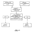
- Fig. 1A shows the components of a system 10 for analyzing body tissue biopotential morphologies for diagnostic or therapeutic-purposes.
- the illustrated embodiment shows the system 10 being used to examine the depolarization of heart tissue that is subject to an arrhythmia.
- the system 10 serves to locate an arrhythmogenic focus for removal by ablation.
- the invention is well suited for use in conducting electrical therapy of the heart.
- the invention is applicable for use in other regions of the body where tissue biopotential morphologies can be ascertained by analyzing electrical events in the tissue.
- tissue biopotential morphologies can be ascertained by analyzing electrical events in the tissue.
- the various aspects of the invention have application in procedures for analyzing brain or neurologic tissue.
- Fig. 1A shows the system 10 analyzing endocardial electrical events, using catheter-based, vascular access techniques. Still, many embodiments of the invention can be used in association with techniques that do not require any intrusion into the body, like surface electrocardiograms or electroencephalograms. Many of the embodiments of the invention also can be used with invasive surgical techniques, like in open chest or open heart surgery, or during brain surgery.
- FIG. 1A shows the system 10 analyzing electrical events within a selected region 12 inside a human heart.
- Figs. 1A and 1B generally show the system 10 deployed in the left ventricle of the heart. Of course, the system 10 can be deployed in other regions of the heart, too. It should also be noted that the heart shown in the Fig. 1 is not anatomically accurate.
- Figs. 1A and 1B show the heart in diagrammatic form to demonstrate the features of the invention.
- the system 10 includes a mapping probe 14 and an ablation probe 16.
- a mapping probe 14 and an ablation probe 16 are separately introduced into the selected heart region 12 through a vein or artery (typically the femoral vein or artery) through suitable percutaneous access.
- the mapping probe 14 and ablation probe 16 can be assembled in an integrated structure for simultaneous introduction and deployment in the heart region 12.
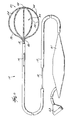
- the mapping probe 14 has a flexible catheter body 18.
- the distal end of the catheter body 18 carries a three dimensional multiple-electrode structure 20.
- the structure 20 takes the form of a basket defining an open interior space 22 (see Fig. 2). It should be appreciated that other three dimensional structures could be used.
- the illustrated basket structure 20 comprises a base member 26 and an end cap 28.
- Generally flexible splines 30 extend in a circumferentially spaced relationship between the base member 26 and the end cap 28.
- the splines 30 are preferably made of a resilient, biologically inert material, like Nitinol metal or silicone rubber.
- the splines 30 are connected between the base member 26 and the end cap 28 in a resilient, pretensed, radially expanded condition, to bend and conform to the endocardial tissue surface they contact.
- eight splines 30 form the basket structure 20. Additional or fewer splines 30 could be used.
- the splines 30 carry an array of electrodes 24.
- each spline 30 carries eight electrodes 24.
- additional or fewer electrodes 24 can be used.
- a slidable sheath 19 is movable along the axis of the catheter body 18 (shown by arrows in Fig. 2). Moving the sheath 19 forward causes it to move over the basket structure 20, collapsing it into a compact, low profile condition for introducing into the heart region 12. Moving the sheath 19 rearward frees the basket structure 20, allowing it to spring open and assume the pretensed, radially expanded position shown in Fig. 2. The electrodes are urged into contact against the surrounding heart tissue.
- the electrodes 24 sense electrical events in myocardial tissue for the creation of electrograms.
- the electrodes 24 are electrically coupled to a process controller 32 (see Fig. 1A).
- a signal wire (not shown) is electrically coupled to each electrode 24.
- the wires extend through the body 18 of the probe 14 into a handle 21, in which they are coupled to an external multiple pin connector 23.
- the connector 23 electrically couples the electrodes to the process controller 32.
- multiple electrode structures can be located epicardially using a set of catheters individually introduced through the coronary vasculature (e.g., retrograde through the aorta or coronary sinus), as disclosed in PCT/US94/01055 entitled “Multiple Intravascular Sensing Devices for Electrical Activity.”
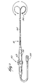
- the ablation probe 16 (see Fig. 3) includes a flexible catheter body 34 that carries one or more ablation electrodes 36.
- Fig. 3 shows a single ablation electrode 36 carried at the distal tip of the catheter body 34.
- other configurations employing multiple ablation electrodes are possible, as described in pending U.S. Patent No. 5,582,609, filed August 8, 1994, entitled “Systems and Methods for Ablating Heart Tissue Using Multiple Electrode Elements.”
- a handle 38 is attached to the proximal end of the catheter body 34.
- the handle 38 and catheter body 34 carry a steering mechanism 40 for selectively bending or flexing the catheter body 34 along its length, as the arrows in Fig. 3 show.
- the steering mechanism 40 can vary.
- the steering mechanism can be as shown in U.S. Patent 5,254,088.
- a wire (not shown) electrically connected to the ablation electrode 36 extends through the catheter body 34 into the handle 38, where it is electrically coupled to an external connector 45.
- the connector 45 connects the electrode 36 to a generator 46 of ablation energy.
- the type of energy used for ablation can vary.
- the generator 46 supplies electromagnetic radio frequency energy, which the electrode 36 emits into tissue.
- a radio frequency generator Model EPT-1000, available from EP Technologies, Inc., Sunnyvale, California, can be used for this purpose.
- the physician places the ablation electrode 36 in contact with heart tissue at the site identified for ablation.
- the ablation electrode emits ablating energy to heat and thermally destroy the contacted tissue.
- the process controller 32 employs electrogram matching to automatically locate for the physician the site or sites potentially appropriate for ablation.
- the process controller 32 is operable to sense electrical events in heart tissue and to process and analyze these events to achieve the objectives of the invention.
- the process controller 32 is also selectively operable to induce electrical events by transmitting pacing signals into heart tissue.
- the process controller 32 is electrically coupled by a bus 47 to a pacing module 48, which paces the heart sequentially through individual or pairs of electrodes to induce depolarization. Details of the process controller 32 and pacing module 48 are described in copending U.S. Patent No. 5,494,042, filed January 28, 1994, and entitled "Systems and Methods for Deriving Electrical Characteristics of Cardiac Tissue for Output in Iso-Characteristic Displays.”
- the process controller 32 is also electrically coupled by a bus 49 to a signal processing module 50.
- the processing module 50 processes cardiac signals into electrograms.
- a Model TMS 320C31 processor available from Spectrum Signal Processing, Inc. can be used for this purpose.
- the process controller 32 is further electrically coupled by a bus 51 to a host processor 52, which processes the input from the electrogram processing module 50 in accordance with the invention to locate arrhythmogenic foci.
- the host processor 32 can comprise a 486-type microprocessor.
- the process controller 32 operates in two functional modes, called the sampling mode and the matching mode.
- the physician deploys the basket structure 20 in the desired heart region 12.
- the physician may have to collapse the basket structure 20, rotate it, and then free the basket structure 20.
- the degree of contact can be sensed by the process controller 32 in various ways.
- the process controller 32 can condition the pacing module 48 to emit pacing signals through a selected electrode 24 or pair of electrodes 24.
- the process controller 32 conditions the electrodes 24 and processing module 50 to detect electrograms sensed by a desired number of the electrodes 24.
- the processing module can also ascertain the desired degree of contact by measuring tissue impedance, as described in copending patent No. 5,598,848, filed March 31, 1994, and entitled "Systems and Methods for Positioning Multiple Electrode Structures in Electrical Contact with the Myocardium.”
- the process controller 32 conditions the electrodes 24 and signal processing module 50 to record electrograms during a selected cardiac event having a known diagnosis. In the sampling mode, the process controller 32 typically must condition the pacing module 48 to pace the heart until the desired cardiac event is induced. Of course, if the patient spontaneously experiences the cardiac event while the structure 20 is positioned, then paced-induction is not required.
- the processor controller 32 saves these electrograms in the host processor 52.
- the process controller 32 creates templates of selected electrogram morphologies by any conventional method, e.g., by having the physician manually select representative electrogram morphologies.
- the process controller 32 typically must condition the pacing module 48 to pace terminate the cardiac event, or the physician may apply a shock to restore normal sinus rhythm.
- the matching mode is conducted without altering the position of the multiple electrode structure 20 in the heart region 12, so that the electrodes 24 occupy the same position during the matching mode as they did during the sampling mode.
- the process controller 32 conditions the pacing module 48 to pace the heart in a prescribed manner without inducing the cardiac event of interest, while conditioning the signal processing module 50 to record the resulting electrograms.
- the process controller 32 operates the host processor 52 to compare the resulting paced electrogram morphologies to the electrogram morphology templates collected during the sampling mode. Based upon this comparison, the host processor 52 generates an output that identifies the location of the electrode or electrodes 24 on the structure 20 that are close to a potential ablation site.
- the process controller 32 operates in the sampling mode while the heart is experiencing a selected cardiac event of known diagnosis and the basket structure 20 is retained in a fixed location in the region 12.
- the selected event comprises an arrhythmia that the physician seeks to treat, for example, ventricular tachycardia (VT), or atrial tachycardia (AT), or atrial fibrillation (AF).
- VT ventricular tachycardia
- AT atrial tachycardia
- AF atrial fibrillation
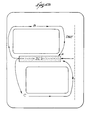
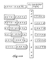
- the signal processing module 50 processes the electrogram morphologies obtained from each electrode during the known cardiac event (designated for the purpose of illustration as E1 to E3 in Fig. 4A).
- the electrograms may be recorded unipolar (between an electrode 24 and a reference electrode, not shown) or bipolar (between electrodes 24 on the structure 20).
- the host processor 52 creates a digital, event-specific template for the morphology sensed at each electrode (designated for the purpose of illustration as T1 to T3 in Fig. 4A).
- the event-specific templates T1 to T3 for each electrode E1 to E3 can be based upon electrogram morphology from one heart beat or a specified number of heart beats.
- the event-specific template T1 to T3 for each electrode E1 to E3 can be created by, for example, having the physician manually select representative electrogram morphologies.
- the template preferably comprises one heart beat and is updated beat by beat. Also preferably, though not essential, the starting point of the template should coincide with the beginning of the depolarization and extend one beat from that point. However, if the arrhythmia event under study is polymorphic, it may be necessary to extend the template over several beats. For example, in bigeminy cases, the template should preferably extend over two beats.
- the host processor 52 retains the set of event-specific templates T1 to T3 in memory.
- the processor 52 can, for an individual patient, retain sets of event-specific templates for different cardiac events. For example, a patient may undergo different VT episodes, each with a different morphology.
- the processor 52 can store templates for each VT episode for analysis according to the invention.
- the templates can be downloaded to external disk memory for off-line matching at a subsequent time, as will be described later. Templates can also be generated based upon mathematical modeling or empirical data and stored for later matching for diagnostic purposes.
- the process controller 32 operates the pacing module 48 to apply pacing signals sequentially to each of the individual electrodes.
- the pacing electrode is designated Ep in Fig. 4A.
- the pacing signal induces depolarization, emanating at the location of the pacing electrode Ep.
- the process controller 32 operates the signal processing module 50 to process the resulting paced electrogram morphologies sensed at each electrode (again designated E1 to E3 for the purpose of illustration in Fig. 4A) during pacing by the selected individual electrode Ep.
- the processed paced electrograms are designated P1 to P3 in Fig. 4A.
- the paced morphology P1 to P3 at each electrode can be from one heart beat or a specified number of heart beats, provided that the length of the morphologies P1 to P3 is not shorter than the length of the event-specific templates T1 to T3 for the same electrodes E1 to E3 obtained during the sampling mode.
- Different conventional pacing techniques can be used to obtain the paced morphologies P1 to P3.
- conventional pace mapping can be used, during which the pace rate is near the arrhythmia rate, but arrhythmia is not induced.
- entrainment or reset pacing is the preferred technique.
- the pacing rate is slightly higher than and the period slightly lower than that observed during the arrhythmia event, thereby increasing the rate of the induced arrhythmia event. Further details of entrainment pacing are found in Almendral et al., "Entrainment of Ventricular Tachycardia: Explanation for Surface Electrocardiographic Phenomena by Analysis of Electrograms Recorded Within the Tachycardia Circuit," Circulation, vol. 77, No. 3, March 1988, pages 569 to 580.
- the pacing stimulus may be monophasic, biphasic, or triphasic.
- the host processor 52 compares the paced morphology P1 to P3 obtained at each electrode E1 to E3 to the stored event-specific template T1 to T3 for the same electrode E1 to E3.
- the comparisons (which are designated C1 to C3 in Fig. 4A) can be performed by using matched filtering or correlation functions, as will be described later.
- the paced morphologies P1 to P3 can be retained in memory or downloaded to external disk memory for matching at a later time.
- the host processor 52 preferably includes an input module 72 for uploading pregenerated templates and/or paced morphologies recorded at an earlier time.
- the input module 72 allows templates and paced morphologies to be matched off-line by the host processor 52, without requiring the real time presence of the patient.
- recorded paced morphologies can be matched in real time using templates generated earlier.
- the pregenerated templates can represent "typical" biopotential events based upon either real, empirical data, or mathematical models for diagnostic purposes, or reflect earlier biopotential events recorded for the same patient or for a patient having the same or similar prognosis.
- the host processor 52 For each pacing electrode Ep(j), the host processor 52 generates a matching coefficient M COEF(i) for each electrode E(i) from the comparison C(i) of the pacing morphology P(i) to the template morphology T(i) for the same electrode E(i).
- both j and i 1 to n, where n is the total number of electrodes on the three dimensional structure (which, for the purpose of illustration in Fig. 4A, is 3).
- the value of the matching coefficient M COEF(i) is indicative for that electrode E(i) how alike the pacing morphology P(i) is to the event-specific template T(i) for that electrode E(i).
- the value of M COEF(i) for each electrode E(i) varies as the location of the pacing electrode Ep(j) changes.
- the value of the matching coefficient M COEF(i) for a given electrode E(i) increases in relation to the closeness of the pacing electrode Ep(j) to the arrhythmogenic foci.
- the host processor 52 while pacing at an individual one of the electrodes Ep(j), the host processor 52 generates from the matching coefficients M COEF(i) for each electrode E(i) an overall matching factor M PACE(j) for the pacing electrode Ep(j).
- the value of the overall matching factor M PACE(j) for the pacing electrode Ep(j) is indicative of how alike the overall propagation pattern observed during pacing at the electrode Ep(j) is to the overall propagation pattern recorded on the associated event-specific templates.
- the process controller 32 operates the pacing module 48 to apply a pacing signal sequentially to each electrode Ep(j) and processes and compares the resulting electrogram morphologies at each electrode E(i) (including Ep(j)) to the event-specific templates, obtaining the matching coefficients M COEF(i) for each electrode E(i) and an overall matching factor M PACE(j) for the pacing electrode Ep(j), and so on, until every electrode E(i) serves as a pacing electrode Ep(j).
- M PACE(j) for each pacing electrode can be derived from associated matching coefficients M COEF(i) in various ways.
- the value of the overall matching factor M PACE(j) increases in relation to the proximity of the particular pacing electrode Ep(j) to a potential ablation site.
- the site appropriate for ablation typically constitutes a slow conduction zone, designated SCZ in Fig. 4B.
- Depolarization wave fronts (designated DWF in Fig. 4B) entering the slow conduction zone SCZ (at site A in Fig. 4B) break into errant, circular propagation patterns (designated B and C in Fig. 4B), called "circus motion.”
- the circus motions disrupt the normal depolarization patterns, thereby disrupting the normal contraction of heart tissue to cause the cardiac event.
- the event-specific templates T(i) record these disrupted depolarization patterns.
- the pacing signal gets caught in the same circus motion (i.e., paths B and C in Fig. 4B) that triggers the targeted cardiac event.
- a large proportion of the associated pacing morphologies P(i) at the sensing electrodes E(i) will therefore match the associated event-specific templates P(i) recorded during the targeted cardiac event. This leads to a greater number of larger matching coefficients M COEF(i) and thus to a larger overall matching factor M PACE(j) .
- Ablating tissue in or close to the slow conduction zone prevents subsequent depolarization.
- the destroyed tissue is thereby "closed” as a possible path of propagation.
- Depolarization events bypass the ablated region and no longer become caught in circus motion. In this way, ablation can restore normal heart function.
- the matching of pacing morphologies P(i) to template morphologies T(i) to create the matching coefficient M COEF(i) and the overall matching factor M PACE(i) can be accomplished in various ways.
- the host processor 52 can employ pattern matching; symmetry matching; matched filtering; cross correlation; or norm of the difference techniques. The following provides an overview of each of these techniques.
- Fig. 5 diagrammatically shows a pattern matching technique that embodies features of the invention.
- the pattern matching technique matched filters the template T(i) for each electrode E(i) using the same template flipped left to right with respect to time, Tflip(i), as coefficients of the matched filter.
- Fig. 6B shows a representative template T(i) for a given electrode E(i).
- Fig. 6C shows Tflip(i), which is the template T(i) (shown in Fig. 6B) flipped right to left.
- Fig. 6E shows a matched filtered output MT(i), which had T(i) (Fig. 6B) as input and Tflip(i) (Fig. 6C) for the same electrode E(i) as coefficients of the matched filter.
- the matched filtered output MT(i) is, for the electrode E(i), a sequence of alternating maximums and minimums, with their values marking a first pattern employed by this technique.
- the pattern matching technique also matched filters the paced electrogram P(i) for each electrode E(i) using an identical matched filter as the one described above.
- Fig. 6A shows a representative paced electrogram P(i) for the given electrode E(i).
- Fig. 6D shows the matched filtered output MP(i), using Tflip(i) shown in Fig. 6C as the matched filtered coefficients.
- the matched filtered output MP(i) is, for each electrode E(i), a sequence of alternating maximums and minimums, which are used to construct a second pattern.
- the pattern matching technique detects the maximums and minimums for the matched filtered template outputs MT(i) and those of MP(i).
- the pattern matching technique computes the norm of the difference between the MP-pattern and the corresponding MT-pattern shifted by an amount, P, that varies from -K to K, where K L/2.
- the maximum number of comparisons for n electrodes will be n comparisons for each pacing electrode. Alternatively, one can shift the MP-patterns as just described, keeping the corresponding MT-patterns fixed. The largest excursions are placed in the centers of the template and paced vectors.
- M PACE(j) ⁇ M COEF ( i ) n
- Fig. 7A shows a symmetry matching technique that embodies features of the invention.
- the symmetry matching technique matched filters the paced electrogram P(i) for each electrode E(i) using Tflip(i) as coefficients of the matched filter.
- Similar electrograms will create a matched filtered output having a positive largest excursion. As the degree of similarity between the two electrograms increases, the matched filtered output will become increasingly more symmetric about this positive absolute maximum.
- the scoring factors based upon SYM are converted to an overall matching factor M PACE(j) for each pacing electrode Ep(j), as previously described.
- the pacing electrode Ep(j) creating the highest overall matching factor is designated to be close to a potential ablation site.
- Fig. 6E shows the matched filtered output MT(i) of the template electrogram of Fig. 6B and its left-to-right flipped counterpart of Fig. 6C.
- the electrogram of Fig. 6B is, in effect, matched filtered against itself, and the symmetry matching technique detects this.
- Fig. 6E shows a largest excursion that is positive and an output that is perfectly symmetric about the positive absolute maximum.
- a perfect scoring factor M COEF(i) of 1.0 would be assigned.
- Fig. 6D is the matched filtered output MP(i) of the electrogram of Fig. 6A and the flipped template in Fig. 6C. These are different, yet similar electrograms.
- the symmetry matching technique detects this close similarity.
- Fig. 6D shows a positive largest excursion, and the output is relatively symmetric about this positive absolute maximum.
- a good scoring factor M COEF(i) of, for example, 0.9 would be assigned.
- Fig. 8C is the matched filtered output of the electrogram of Fig. 6A using the flipped template shown in Fig. 8B as coefficient of the matched filter. It can be seen that the electrogram shown in Fig. 8A has a morphology quite different than that shown in Fig. 6A. The symmetry matching technique detects this difference. Fig. 8C shows a negative largest excursion and an output that is not symmetric about this absolute maximum. A poor scoring factor M COEF(i) of zero would be assigned.
- Fig. 9 shows a technique matching against Dirac pulse that embodies features of the invention.
- This matching technique employs a whitening algorithm to first filter the template electrograms and the paced electrograms.
- the whitening filter transforms so-called colored noise, which can be 60-Hz (or 50-Hz) interference, or motion or muscular artifacts of the patient, to white noise.
- the technique matched filters the whitened paced electrogram for each electrode using the left-right flipped, whitened template for that electrode as coefficients of the matched filter. Ideally, exactly matched, whitened electrograms will produce an output that equals a Dirac pulse. Therefore, each filter output is compared to a Dirac pulse. An algorithm scores the similarity for each electrode.
- the pacing electrode whose whitened, matched filtered output most closely resembles a Dirac pulse is designated to be close to a potential ablation site.
- Fig. 10 shows a cross correlation technique that embodies features of the invention.
- This technique uses an appropriate algorithm to calculate for each electrode the cross correlation function between the template electrogram and the paced electrogram. For identical electrograms, the largest excursion of the cross correlation function will equal 1.0.
- M COEF(i) is equal to the largest excursion of the sequence ⁇ rxy(k) ⁇ computed for the individual electrode E(i) (i.e., the largest excursion can be either negative or positive, depending upon the degree of intercorrelation).
- the pacing electrode Ep(j) having an overall matching factor M PACE(j) closest to 1.0 is designated to be close to a potential ablation site. Additional information may be contained in the shift parameter k for each electrode.
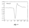
- Fig. 11A shows the cross correlation function for the electrograms of Fig. 6A and Fig. 6B. These electrograms are quite similar, and the cross correlation technique detects this.
- the largest excursion of the cross correlation function in Fig. 11A is near 1.0 (i.e., it is 0.9694).
- Fig. 11B shows the cross correlation function for the unlike electrograms shown in Figs. 6A and 8A.
- the cross correlation technique detects this lack of similarity.
- the largest excursion in Fig. 11B is negative (i.e., it is -0.7191).
- Fig. 12 shows a norm of the difference technique that embodies features of the invention.
- This technique normalizes, for each electrode, the template electrogram with respect to the absolute value of its largest excursion from baseline. This technique also normalizes, for each electrode, the paced electrogram with respect to the largest excursion from baseline. The technique then calculates, for each electrode, the norm of the difference between the template electrogram and the paced electrogram. The norm will decrease in proportion to the similarity of the electrograms.
- Fig. 13A is the difference between the similar electrograms shown in Figs. 6A and 6B, after each was normalized with respect to its largest excursion. This technique detects the similarity with a relatively small norm of the difference (i.e., it is 0.9620).
- Fig. 13B is the difference between the dissimilar electrograms shown in Figs. 6A and 8A, after each was normalized with respect to its largest excursion. This technique detects the lack of similarity with a relatively high norm of the difference (i.e., it is 2.4972).
- the technique preferably uses a weighted averaging algorithm to average, for each pacing electrode, the norm of the differences for all recording electrodes.
- the pacing electrode having the smallest average norm of the differences is designated the appropriate place to ablate.
- the electrograms may or may not be filtered before analysis.
- a 1 to 300 Hz bandpass filter may be used for filtering. If a filter is used to reduce the noise for an electrogram that is used as a template, the same filter must also be used for the paced electrograms, since filtering may alter the electrogram morphology.
- the electrograms might need to be aligned prior to processing. Any columnar alignment technique can be used. For example, the electrograms could be aligned about the point of largest positive slope.
- an analog matched filter can be implemented with analog integrators and adders.
- optical realizations of such filters can be implemented, for example, by using optical slots to represent the template. After optical conversion, the input signal is passed through the optical slot. The average light intensity behind the optical slot plane is maximal when the shape of the optically converted input signal matches the shape of the slot.
- An optical sensor can measure the average light intensity and output a signal that represents the matched coefficient M COEF(i) .
- the host processor 52 sets a match target N Match , which numerically establishes a matching factor M PACE(j) at which a high probability exists that the pacing electrode is close to a potential ablation site.
- N MATCH 0.8.
- M PACE(j) > N MATCH the host processor 52 deems the location of the pacing electrode Ep(j) to be close to a potential site for ablation.
- the host processor 52 transmits a SITE signal to an associated output display device 54 (see Fig. 1A). Through visual prompts, the display device 54 notifies the physician of the location of the pacing electrode Ep(j) and suggests that the location as a potential ablation site.
- the host processor 52 sorts to locate the M PACE(j) having the highest value. In this instance, the host processor 52 deems the pacing electrode Ep(j) with the highest M PACE(j) to be the one having the highest likelihood for being close to a potential ablation site and transmits the SITE signal accordingly.
- the process controller 32 provides iterative pacing and matching using different pacing and matching techniques. Using different pacing-and-compare techniques allows the comparison of the location output from one technique with the location output from one or more different techniques. Using iterative pacing and matching, the process controller 32 and the host processor 52 confirm and cross-check the location output to verify its accuracy before ablation. The host processor 52 can also rely upon alternative diagnostic techniques to analyze the biopotential morphology.
- the system 10 also includes a roving pacing probe 68 usable in tandem with the basket structure 20 to generate and verify the location output.
- the process controller 32 includes a module 60 that allows the physician to select among different types of pacing techniques.
- the different pacing techniques allow the physician to conduct both global and localized site identification, with and without inducing the abnormal cardiac event.
- At least one technique is appropriate for pacing a large tissue region to identify a subregion close to a potential ablation site, without the need to induce an abnormal cardiac event.
- the process controller 32 first conditions the pacing module 48 in the mode to conduct pace mapping. Pace mapping uses all electrodes 24 on the structure 20 in sequence as the pacing electrode, and does not induce the cardiac event. Based upon pace mapping, the process controller 32 obtains a location output that points to a general subregion that is close to a potential ablation site.
- the process controller 32 conditions the pacing module 48 in the matching mode to carry out entrainment or reset pacing, using the electrodes in the general subregion as the pacing electrodes. Entrainment or reset pacing in this subregion overdrives the arrhythmia, and provides enhanced differentiation of slow conduction zones. The process controller 32 thereby obtains a location output that is more localized with respect to the potential ablation site.
- the process controller 32 also includes a module 62 that allows the physician to select more than one matching technique during iterative pacing.
- the process controller 32 may, during pace mapping or entrainment/reset pacing, compare the templates to the paced electrograms by first pattern matching, then by symmetry matching, and then by norm of the difference. In this way, the process controller 32 determines the uniformity of the location output among the different matching techniques. The correspondence of the location outputs confirms their reliability.
- the process controller 32 is also electrically coupled by a bus 64 to a diagnostic module 66.
- the diagnostic module 66 conducts one or more alternative analyses of heart activity to cross check or verify the output location that the process controller 32 generates based upon electrogram matching.
- the module 66 determines the fractionation of the paced electrograms.
- the degree of fractionation can be used as a cross-check that the physician can employ to cross-check and verify the output location or locations that the process controller 32 yields when operated in the matching mode.
- the location output may comprise a single electrode 24 or several electrodes 24 in a localized region of the structure 20.
- the system 10 further includes a roving pacing probe 68 that can be deployed in the heart region 12 while the multiple electrode structure 20 occupies the region 12.
- the roving probe 68 is electrically coupled to the pacing module 48 to emit pacing signals.
- the physician positions the roving electrode probe 68 within the localized region near the output location electrode or electrodes 24.
- the process controller 32 preferably includes a homing module 70 to aid the physician in guiding the roving electrode probe 68 in the localized region within the structure 20.
- Systems and methods for operating the homing module 70 are disclosed in copending patent No. 5,885,278, filed October 11, 1994, and entitled “Systems and Methods for Guiding Movable Electrode Elements Within Multiple Electrode Structures".
- the process controller 32 conditions the pacing module 48 to emit pacing signals through the roving pacing probe 68 to pace the heart in the localized region, while the electrodes 24 record the resulting electrograms. By pacing this localized region with the roving pacing probe 68, while comparing the paced electrograms with the templates, the process controller 32 provides the capability of pacing and comparing at any location within the structure 20. In this way, the process controller 32 generates as output a location indicator that locates a site as close to a potential ablation site as possible.
- iterative pacing and matching techniques as above described, can be practiced using the roving pacing probe 68.
- the basket structure 20 cannot contact the entire wall of a given heart chamber.
- the preferred implementation of the system 10 (as Fig. 1B shows) therefore deploys the roving pacing probe 68 outside the structure to pace the heart in those wall regions not in contact with the electrodes 24.
- the roving pacing probe 68 can also be deployed while the basket structure 20 occupies the region 12 to pace the heart in a different region or chamber.
- the electrodes 24 on the structure 20 record the resulting paced electrograms for comparison by the process controller 32 to the templates.
- the process controller 32 is thus able to generate an output identifying a location close to a potential ablation site, even when the site lies outside the structure 20 or outside the chamber that the structure 20 occupies.
- the physician deploys the ablation electrode 36 to the location of the pacing electrode Ep(j) to conduct the ablation (as Fig. 1A shows).
- the homing module 70 (as already described and as shown in Fig. 1B) can also be used to aid the physician in deploying the ablation electrode 36 to the designated site, as disclosed in copending patent No. 5,885,278, filed October 11, 1994, and entitled "Systems and Methods for Guiding Movable Electrode Elements Within Multiple Electrode Structures".
- the system 10 is not limited to the diagnosis and treatment of arrhythmia events.
- the system 10 can be used in the sampling mode, for example, to create templates while the heart is in sinus rhythm.
- the heart In the matching mode, the heart can be paced at sinus rhythm rates and the paced electrograms compared to the templates to detect abnormal activation patterns associated with other forms of heart disease or to identify the presence of accessory pathways.
- the template electrograms at all electrodes 24 are recorded during the same time interval.
- the pacing electrograms for each pacing electrode Ep(j) are recorded at all electrodes 24 during the same time interval. This technique requires the process controller 32 to have parallel processing channels equal in number to the number of electrodes 24 conditioned to record the electrograms.
- the process controller 32 must be capable of handling thirty-two (32) parallel channels of information.
- the process controller 32 can be operated in a time-sequential recording mode. In this mode, the process controller 32 records electrograms, either to create a template or to create paced electrograms for matching, at different time intervals. In this mode, the process controller 32 consolidates the time-sequential electrograms for composite analysis, as if the electrograms were recorded during the same time intervals.
- the time-sequential mode can be used when the waveshapes of the electrograms to be analyzed are generally the same during each heart beat. For example, monomorphic VT is characterized by such time-invariant electrogram waveshapes.
- the time-sequential mode allows the physician to condition the process controller 32 to record time invariant electrograms in numbers greater than the number of processing channels that the process controller 32 has.
- the process controller 32 can only accommodate twenty (20) channels of data at a given time, the time-sequential mode nevertheless allows information from thirty-two (32) electrograms to be recorded and processed.
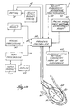
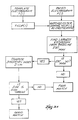
- Fig. 21 shows the time-sequential mode of operation in diagrammatic flow chart form.
- the time-sequential mode simultaneously records electrograms at first electrode sites ES(1).
- the first electrode sites ES(1) number twenty (20) and are designated E(1) to E(20).
- the electrograms for the first site electrodes E(1) to E(20) are retained for the first time interval TI(1).
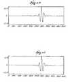
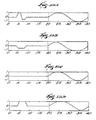
- Fig. 22A shows representative electrograms recorded at E(1) during TI(1).
- Fig. 22B shows a representative electrogram recorded at E(2) during TI(1).
- the time-sequential mode simultaneously records electrograms at second electrode sites, at least one of which is an electrode site used during the first time interval TI(1).
- Fig. 21 identifies E(1) as the common electrode site.
- E(21) to E(32) comprise the remaining electrodes in ES(2).
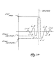
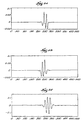
- Fig. 22C shows representative electrograms recorded at the common electrode site E(1) during TI(2).
- Fig. 22D shows representative electrograms recorded at the additional electrode site E(21) during TI(2).
- the time-sequential mode determines the time difference TD between the electrograms for E(1) at TI(1) and TI(2).
- Fig. 22C shows TD.
- Fig. 23C shows the representative electrograms recorded at E(1) during TI(2) after time-alignment with the electrograms recorded at E(1) during TI(1), which are shown in Fig. 23A.
- the time-sequential mode also left-shifts the electrograms E(21) through E(32) by the same amount TD.
- Fig. 23D shows the representative electrograms recorded at E(21) during TI(2) after time-alignment.
- the time-sequential mode creates the electrogram composite EC, which consists of the time-registered electrograms E(1) to E(32) taken at TI(1) and TI(2).
- the time-alignment process of creating the electrogram composite EC can be done manually by the physician, by interacting with the display device 54.
- the host processor 52 automatically analyzes the signals, computes TD, and accomplishes the time-alignment to create the composite electrogram EC.
- TD need not be computed.
- the physician or the operator can make use of any time-assignment method to align the signals based on the information contained in the common channels E(1).
- An example of useful information is the location of the maximal slopes of E(1).
- this algorithm can be automatically implemented and executed.
- the time-aligned electrogram composite EC can be analyzed in the same manner as electrograms taken simultaneously during the same time interval.
- the electrogram composite EC can be used to create the electrogram template, or to create paced electrograms for comparison with an electrogram template, or as electrograms for any other diagnostic purpose.
- signals derived from biological events can be processed, such as electrocardiograms, tissue biopotential signals, pressure waves, electrogastrograms, electromyograms, electroencephalograms, impedance measurements, and temperature measurements.
- the endocardially positioned basket structure 20 both paces and senses the resulting electrograms.
- the process controller 32 can condition the pacing module 48 in the sampling mode to pace the heart to induce a desired cardiac event, using individual or pairs of electrodes 24 on the basket structure 20 deployed in the heart region 12 (as already described), while creating templates of the resulting electrocardiograms recorded by the processing module 50 from body surface electrodes electrically coupled to the process controller 32.
- the process controller 32 paces the heart with the individual or pairs of endocardial electrodes 24 positioned on the structure 20 in the heart region 12.
- the resulting paced electrocardiograms are recorded by the same body surface electrodes (located in the same position as during the sampling mode) and compared to the electrocardiogram templates in the manner above described.
- the process controller 32 generates the location output based upon comparing the electrocardiogram sample templates with endocardially paced electrocardiograms.
- Endocardially paced electrocardiograms can also be used to identify regions of slow conduction.
- the process controller 32 conditions the pacing module 48 to pace the heart with the individual or pairs of electrodes 24 positioned on the structure 20 endocardially in the heart region 12, the resulting endocardially paced electrocardiograms are recorded by body surface electrodes coupled to the process controller 32. From the endocardially paced electrocardiograms, the process controller 32 measures the time difference between the pacing signal and the onset of the Q-wave to detect slow conduction regions (characterized by abnormally large time delays).
- the process controller 32 generates maps displaying iso-time delay regions based upon these endocardially paced electrocardiograms, to further aid in the location of the slow conduction region.
- Time delays obtained from endocardially paced electrocardiograms can also characterize heart tissue morphology.
- the body surface electrodes record electrocardiograms while the pacing module 48 paces the heart with the individual or pairs of electrodes 24 positioned on the structure 20 in the heart region 12.
- the pacing module 48 first paces the heart at or near normal sinus rhythm rates.
- the process controller 32 registers the time delays recorded from the resulting electrocardiograms.
- the pacing module 48 next paces the heart at an increased rate, e.g., at or near an arrhythmia rate.
- the process controller 32 registers the resulting time delays from the resulting electrocardiograms.
- the process controller 32 compares the paced sinus rate time delays with the paced arrhythmia rate time delay.
- the location of the pacing electrodes where the time delays shortened as the pacing rate increased are near regions of healthy tissue.
- the location of pacing electrodes where the time delays lengthened as the pacing rate increased are near regions of ischemic tissue.
- the process controller 32 preferably generates iso-display maps showing the distribution of the time delay differences, thereby aiding the physician in differentiating between regions of healthy and ischemic tissue.
- Pacing artifacts in the pacing electrograms may be eliminated by conventional techniques to better discern the initial point of depolarization.
- the process controller 32 includes a filter 56 (see Fig. 4) that removes the pacing artifact for this purpose without otherwise altering the morphology of the electrogram.
- the operation of the filter 56 may vary.
- the filter 56 implements a nonlinear sorting algorithm of the type shown in Fig. 14A.
- Fig. 14B shows a representative implementation and filter output for the algorithm in diagrammatic form.
- the algorithm establishes a sample window.
- the sample window has a predetermined length (WL), expressed in terms of the number of discrete sample points the window contains.
- the predetermined length (WL) of the sample window takes into account the length (AL) of the pacing artifact, which is expressed in terms of the number of sample points that encompass the pacing artifact.
- the window length WL is an odd number.
- WL is significantly smaller than twice AL, the sorting algorithm will not serve to eliminate the pacing artifact to the extent necessary to accurately discern the initial point of depolarization. There is, however, a limitation placed upon how large WL is relative to the size of AL. When WL is significantly larger than twice AL, the morphology of the electrogram will be distorted by being spread out with respect to time.
- the algorithm sorts the sample values X(n) in the window from smallest value to largest value.
- the algorithm outputs the sample value X(p[f]) contained in the selected sort position, which constitutes the filter output for the boxcar sample.
- the algorithm outputs X(p[f]) and advances the window forward in time one sample point.
- the algorithm repeats the sorting process, generating a filter output for each boxcar sample and advancing the window, until the entire electrogram has been processed.
- the algorithm then plots the filter outputs with respect to time, which constitutes the filtered electrogram.
- the sequence of sample values X(1 to 5) constitutes the boxcar sample.
- the algorithm sorts the sequence X(1 to 5) in increasing numerical value, or X(2) ⁇ X(1) ⁇ X(5) ⁇ X(4) ⁇ X(3).
- the algorithm establishes the sort positions p(n) based upon this permutation, or X(p(n)) X(p(1)) X(p(2)) X(p(3)) X(p(4)) X(p(5)) Value 2 4 6 8 10
- the algorithm selects a sort position p(f) according to prescribed criteria.
- the criteria for selecting the sort position takes into account the length of the artifact AL, as will be discussed later.
- the criteria specifies the sort position relative to the other sort positions.
- (f) is expressed as a position (z) of WL positions, i.e., p(z/WL), where WL is the size of the sort window.
- the position z is selected taking into account AL, and, more particularly, z should increase as AL decreases.
- p(3/5) means that X(p(3)) replaces x(3) in the output sequence.
- the value X(p(3)) is 6, which becomes the filter output for this boxcar sample, based upon the selected sort position criteria.
- the value X(p(4)) is 8, which becomes the nonlinear, non-median filter output for this boxcar sample, based upon the selected sort position criteria. This corresponds to x(4) of the output sequence.
- the algorithm advances the window one sample at a time, sorting the sample enclosed within the window, and generating a filter output based upon the sort criteria, and so on until the entire electrogram has been filtered.
- the algorithm keeps the timing of filter output in sequence with the timing of the electrogram by retaining the value of edge samples, so that the number of filter outputs equal the number of electrogram samples.
- the number of edge values retained depends upon the size of the sample window WL.
- the algorithm retains a prescribed number, y 1 , of beginning sample values a number, y 2 , of ending sample values, arranging the filter output between the prescribed number of beginning and ending sample values to keep the filter output arranged with respect to time in sequence with the derived biological signal.
- Fig. 14B shows the filtering of ten sample points (4 2 7 5 1 10 3 8 9 6) in accordance with the above described technique.
- the window length WL in Fig. 14B is 5, and the sort criteria is median filtering, i.e. p(3/5).
- Fig. 14B also shows the filter outputs (4 5 5 5 8 8) between the edge samples, with the sorted samples appearing to the right of the filter outputs.
- Fig. 14C shows the filtering of the same ten sample points (4 2 7 5 1 10 3 8 9 6), with the same window length WL of 5, but with a non-median sort criteria p(4/5).
- Fig. 14C shows the filter output for the p(4/5)-criterion: (5 7 7 8 9 9) between the edge samples.
- the selection of the sort position p(f) takes into account the morphology of the pacing artifact in terms of the length of the artifact AL, expressed in terms of the number of sample points that encompass it.
- the percentage value of f should increase as the artifact length AL decreases, or, given a constant WL, z should increase as AL decreases.
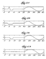
- Fig. 15A shows a simulated pacing artifact where AL is 5 and the width of the highest peak is 3.
- Fig. 15B shows the filtered output for p(2/5);
- Fig. 15C shows the filtered output for the median, or p(3/5); and
- Fig. 15D shows the filtered output for p(4/5).
- the criteria p(2/5) fully eliminated the pacing artifact (Fig. 15B), whereas the criteria p(3/5) and p(4/5) did not (Figs. 15C and 15D, respectively).
- the optimal elimination of certain pacing artifacts requires nonlinear, non-median filtering, where the position z comprises a positive integer; 1 ⁇ z ⁇ WL; and: z ⁇ [ WL + 1 2 ]
- Fig. 16A shows a simulated pacing artifact where AL is 5 and the width of the highest peak is 2.
- Fig. 16B shows the filtered output for p(2/5);
- Fig. 16C shows the filtered output for p(3/5), i.e. the median; and
- Fig. 16D shows the filtered output for p(4/5).
- the criteria p(3/5) fully eliminated the pacing artifact (Fig. 16C), whereas the criteria p(2/5) and p(4/5) did not (Figs. 16B and 16D, respectively).
- Fig. 17A shows a simulated pacing artifact where AL is 5 and the width of the highest peak is 1.
- Fig. 17B shows the filtered output for p(2/5);
- Fig. 17C shows the filtered output for p(3/5), i.e. the median; and
- Fig. 17D shows the filtered output for p(4/5).
- the criteria p(4/5) fully eliminated the pacing artifact (Fig. 17D), whereas the criteria p(2/5) and p(3/5) did not (Figs. 17B and 17C, respectively).
- Fig. 18A shows a paced electrogram consisting of 500 samples taken in increments of 0.5 seconds.
- Fig. 18C shows a reduction in the size but not an elimination of the pacing artifact PA by median filtering.
- Fig. 18B shows an elimination of the pacing artifact by median filtering.
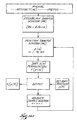
- the filter 56 can implement the adaptive filtering algorithm shown in Fig. 19 to remove the pacing artifact.
- the filter 56 generates an internal variable TPACE(t) expressing a template of the pacing artifact itself.
- the function TPACE(t) preferably begins with a preestablished template typical for a pacing artifact.
- the algorithm can create an initial template by manually selecting a window about the artifact and creating a template by, for example, conventional signal averaging techniques. This template could be adaptively updated using appropriate signal averaging techniques.
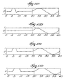
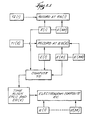
- Figs. 24 to 28 exemplify a preferred way of generating a template of the pacing artifact.
- Fig. 24 shows a portion of a recording of a paced electrogram extending over about two beats and a half.
- Fig. 24 shows three pacing pulses (PA-1; PA-2; PA-3), which are the artifacts that are to be ultimately removed.
- PA-1 pacing pulses
- PA-3 pacing pulses
- the physician preferably selects windows about each pacing pulse PA-1 to 3 to create an averaged template.
- the physician can select one of the pacing pulse, for example PA-1, to generate the template.
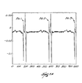
- Figs. 25A to C represent the signals PS-1; PS-2; and PS-3 contained by the three windows manually selected about the pacing pulses, respectively PA-1; PA-2; and PA-3.
- the physician manually aligns the three signals PS-1; PS-2; and PS-3 and truncates them at the same length, as Figs. 26A to C show.
- the three signals PS-1; PS-2; and PS-3 have been aligned about their largest positive peak, although other alignment techniques could be used.
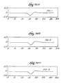
- Fig. 27 shows the template TPACE(t) of the pacing artifact generated by averaging the three signals PS-1; PS-2; and PS-3 after alignment and truncation (i.e., the signals shown in Figs. 26A to C are averaged).
- the template TPACE(t) (Fig. 28B) is aligned with the first pacing pulse in the electrogram (Fig. 28A) prior to executing the adaptive algorithm for artifact removal.
- TPACE(t) It is not necessary to generate a new pacing artifact template TPACE(t) for the electrogram sensed by each electrode.
- the same initial template TPACE(t) from only one of the electrodes can be used for every electrogram.
- pacing signals from different electrodes can be aligned for averaging to create the template TPACE(t), which is then used for all electrograms.
- the template TPACE(t) can also be generated by approximating the pacing pulse using suitable mathematical techniques, for example, spline interpolation.
- a universal template TPACE(t) can also be generated from recordings taken from different patients at different times with different equipment, although such different records may require proper adjustment before generating the universal template TPACE(t).
- the template TPACE(t) of the filter 56 reduces IN(t), so the output signal EG(t) is expressed as IN(t) - TPACE(t).
- the filter 56 changes TPACE(t) over time based upon the energy of the output EG(t) so as to minimize the energy of (PACE(t) - TPACE(t)) over time, and therefore, the energy of EG(t).
- the filter 56 seeks to minimize the function EG(t) + PACE(t) - TPACE(t) over time. Ideally, the energy of EG(t) is minimized over time when TPACE(t) equals PACE(t), therefore being equal to the energy of EG(t).
- the filter algorithm changes TPACE(t) over time applying known iterative techniques.
- LMS Least-Mean-Squares
- the template for TPACE(t) is used as a reference input for the LMS algorithm.
- the weight vector is initialized at [K 0 0 ... 0].
- K is chosen equal to the ratio between the peak of PACE(t) and the peak of the template TPACE(t).
- PACE(t) TPACE(t)
- k is equal to one. Further details of LMS are found in "Adaptive Filter Theory" by S. Haykin (Prentice Hall, 1991)
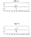
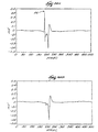
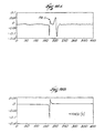
- Fig. 20A shows a representative paced electrogram.
- the designation PA in Fig. 20A marks the location of the pacing artifact.
- Fig. 20B shows the paced electrogram after filtering using the LMS technique above described.
- Fig. 20B shows the effectiveness of the adaptive filter to remove the pacing artifact, without otherwise altering the morphology of the paced electrogram.
- Either of the above described techniques for removing the pacing artifact have application outside the conditioning of the electrogram for morphology matching described herein. Either technique has application whenever it is desired to remove an artifact signal from a useful signal or to otherwise eliminate virtually any signal of a known shape.
- nonlinear filtering or adaptive filtering can be used whenever it is desired to remove cardiac related or other periodic artifacts, for example, in respiratory signals, or EEG's, or from neurological signals.
- Nonlinear filtering or adaptive filtering can also be used to eliminate periodic artifacts that are not cardiac related, for example, 50 to 60 Hz noise from sensed signals due to poor power source isolation.
- nonlinear filtering or adaptive filtering can also be used to remove the pacing artifact before measuring the level of fractionation in an electrogram. Since a pacing artifact looks much like an electrogram, it is desirable to remove it before analyzing for actual fractionation.
- nonlinear filtering or adaptive filtering can be used to remove a pacing artifact when it is desired to conduct a frequency domain analysis of the cardiac signal, to determine the regularity of the heart beat.
- any portion of the electrogram can be isolated for elimination using the filtering techniques described above, not merely the pacing artifact.
- the nonlinear and adaptive filtering techniques can be used in applications where low pass filtering cannot be used.
- body surface mapping can use low pass filtering of electrograms
- endocardial mapping cannot, due to the use of higher frequencies than in electrocardiograms.
- a common electrocardiogram frequency spectrum is .05 to 100 Hz
- a common bipolar electrogram spectrum is 1 to 300 Hz.
- Nonlinear filtering or adaptive filtered can be used for processing or analyzing virtually any signal derived from a biological event.
- nonlinear filter or adaptive filtering can be used to process or analyze electroencephalograms, respiratory signals, electrogastrograms, and electromyograms.
Landscapes
- Health & Medical Sciences (AREA)
- Life Sciences & Earth Sciences (AREA)
- Veterinary Medicine (AREA)
- Engineering & Computer Science (AREA)
- Biomedical Technology (AREA)
- Heart & Thoracic Surgery (AREA)
- Animal Behavior & Ethology (AREA)
- General Health & Medical Sciences (AREA)
- Public Health (AREA)
- Cardiology (AREA)
- Biophysics (AREA)
- Surgery (AREA)
- Pathology (AREA)
- Physics & Mathematics (AREA)
- Medical Informatics (AREA)
- Molecular Biology (AREA)
- Radiology & Medical Imaging (AREA)
- Nuclear Medicine, Radiotherapy & Molecular Imaging (AREA)
- Physiology (AREA)
- Vascular Medicine (AREA)
- Measurement And Recording Of Electrical Phenomena And Electrical Characteristics Of The Living Body (AREA)
- Measuring And Recording Apparatus For Diagnosis (AREA)
- Measuring Pulse, Heart Rate, Blood Pressure Or Blood Flow (AREA)
- Measurement Of The Respiration, Hearing Ability, Form, And Blood Characteristics Of Living Organisms (AREA)
Claims (10)
- Ein System (10) zum Erzeugen eines von einem biologischen Ereignis abgeleiteten zusammengesetzten Signals (EC), aufweisend:vielfache Sensoren (24) zum Wahrnehmen von Signalen, die von dem biologischen Ereignis abgeleitet sind, wobei die vielfachen Sensoren (24) eine erste Sensor-Gruppe (ES1) und eine zweite Sensor-Gruppe (ES2) aufweisen mit mindestens einem gemeinsamen Sensor (E1), der Teil der ersten Gruppe (ES1) ist, und mit anderen Sensoren (E21-E32), die nicht Teil der ersten Gruppe (ES1) sind, undein Verarbeitungs-Element (32), das mit den vielfachen Sensoren (24) gekoppelt ist, wobei das System dadurch gekennzeichnet ist, dassdie Sensoren (E21-E32), die nicht Teil der ersten Sensor-Gruppe sind, konfiguriert sind zum Wahrnehmen von Signalen an Stellen (ES2), die von den Stellen von Sensoren unterschiedlich sind, die in der ersten Gruppe (ES1) sind,das Verarbeitungs-Element (32) funktionsfähig ist zum Erzeugen des zusammengesetzten Signals (EC),das Verarbeitungs-Element (32) konfiguriert ist zum Konditionieren der ersten Sensor-Gruppe (ES1) zum Wahrnehmen eines ersten Satzes von Signalen abgeleitet von dem biologischen Ereignis während eines ersten Zeitintervalls (T1),das Verarbeitungs-Element (32) ferner konfiguriert ist zum Konditionieren der zweiten Sensor-Gruppe (ES2) zum Wahrnehmen eines zweiten Satzes von Signalen abgeleitet von dem biologischen Ereignis während eines zweiten Zeitintervalls (T2) sequentiell nach dem ersten Zeitintervall (T1), unddas Verarbeitungs-Element (32) ferner konfiguriert ist zum Zeit-Ausrichten der ersten und zweiten Sätze von Signalen mittels Verschiebens von einem der Sätze von Signalen bis das mittels des mindestens einen gemeinsamen Sensors (E1) während des ersten Zeitintervalls (T1) wahrgenommene Signal ausgerichtet ist zu dem mittels des mindestens einen gemeinsamen Sensors (E1) während des zweiten Zeitintervalls (T2) wahrgenommenen Signals, wodurch ein zusammengesetztes Signal (EC) erzeugt wird.
- Ein System (10) gemäß Anspruch 1, wobei das Verarbeitungs-Element (32) ferner konfiguriert ist zum Analysieren des zusammengesetzten Signals (EC).
- Ein System (10) gemäß Anspruch 1 oder 2, wobei die ersten und zweiten Sätze von Signalen Atmungs-Signale, Elektrogramme, Elektrokardiogramme, Gewebe-Biopotentiale, Druckwellen, Elektrogastrogramme, Elektromyogramme, Elektroencephalogramme, Impedanzmessungen oder Temperaturmessungen aufweisen.
- Ein System (10) gemäß Anspruch 1, wobei die erste (ES1) und zweite (ES2) Sensor-Gruppe erste bzw. zweite Elektroden-Gruppen aufweist, und wobei der erste und zweite Satz von Signalen erste bzw. zweite Muster von Biopotentialen aufweist, die in dem Gewebe-Bereich auftreten.
- Ein System (10) gemäß Anspruch 1,
wobei das System (10) ferner erste und zweite Sätze von Verarbeitungskanälen aufweist, die mit dem Verarbeitungs-Element (32) gekoppelt sind, und die erste Gruppe von Sensoren (ES1) andere Sensoren (E2-E20) aufweist, die nicht Teil der zweiten Gruppe (ES2) sind,
wobei das Verarbeitungs-Element (32) ferner konfiguriert ist zum jeweiligen Koppeln des mindestens einen gemeinsamen Sensors (E1) und der anderen Sensoren (E2-E20) der ersten Gruppe (ES1) mit den ersten und zweiten Sätzen von Verarbeitungs-Kanälen während des ersten Zeitintervalls (T1) zum Aufnehmen eines ersten Satzes von biologischen Ereignissen, und zum jeweiligen Koppeln des mindestens einen gemeinsamen Sensors (E1) und der anderen Sensoren (E21-E32) der zweiten Gruppe (ES2) mit den ersten und zweiten Sätzen von Verarbeitungs-Kanälen während des zweiten Zeitintervalls (T2) zum Aufnehmen eines zweiten Satzes von biologischen Ereignissen, und
wobei das Verarbeitungs-Element (32) ferner konfiguriert ist zum Zeit-Ausrichten der ersten und zweiten Sätze von biologischen Signalen unter Verwendung der biologischen Signale, die mittels des mindestens einen gemeinsamen Sensors (E1) wahrgenommen sind, zum Erzeugen eines zusammengesetzten Satzes von biologischen Signalen, wahrgenommen mittels der vielfachen Sensoren (24). - Ein System gemäß Anspruch 5, wobei die ersten und zweiten Sätze von Signalen Atmungs-Signale, Elektrogramme, Elektrokardiogramme, Gewebe-Biopotentiale, Druckwellen, Elektrogastrogramme, Elektromyogramme, Elektroencephalogramme, Impedanzmessungen oder Temperaturmessungen aufweisen.
- Ein System (10) gemäß einem der vorigen Ansprüche, wobei das Verarbeitungs-Element (32) ferner konfiguriert ist zum Zeit-Ausrichten der ersten und zweiten Sätze von Signalen mittels Verschiebens der ersten und zweiten Sätze von Signalen, ohne einen Zeitunterschied zwischen ihnen zu berechnen.
- Ein System (10) gemäß Anspruch 7, wobei das Verarbeitungs-Element (32) ferner konfiguriert ist zum Verschieben der ersten und zweiten Sätze von Signalen basierend auf den Lagen von maximalen Steigungen von Signalen, die von dem mindestens einen gemeinsamen Sensor kommen.
- Ein System (10) gemäß Anspruch 1 oder 4, wobei das Verarbeitungs-Element (32) ferner konfiguriert ist zum Zeit-Ausrichten der ersten und zweiten Sätze von Signalen mittels Berechnens einer Zeitdifferenz zwischen den ersten und zweiten Sätzen von Signalen zu dem Zweck, sie zeitlich zu registrieren.
- Ein System (10) gemäß Anspruch 9, wobei das Verarbeitungs-Element (32) die Zeitdifferenz berechnet basierend auf den Zeit-Differenzen (TD) von Peaks der Signale, die von der mindestens einen gemeinsamen Elektrode (E1) kommen.
Applications Claiming Priority (3)
| Application Number | Priority Date | Filing Date | Title |
|---|---|---|---|
| US39054095A | 1995-02-17 | 1995-02-17 | |
| US390540 | 1995-02-17 | ||
| PCT/US1996/002090 WO1996025095A1 (en) | 1995-02-17 | 1996-02-14 | Systems and methods for making time-sequential measurements of biological events |
Publications (3)
| Publication Number | Publication Date |
|---|---|
| EP0809463A1 EP0809463A1 (de) | 1997-12-03 |
| EP0809463A4 EP0809463A4 (de) | 1999-01-07 |
| EP0809463B1 true EP0809463B1 (de) | 2002-07-10 |
Family
ID=23542882
Family Applications (1)
| Application Number | Title | Priority Date | Filing Date |
|---|---|---|---|
| EP96906473A Expired - Lifetime EP0809463B1 (de) | 1995-02-17 | 1996-02-14 | Anordnung für sequentielles messen biologischer ereignisse |
Country Status (8)
| Country | Link |
|---|---|
| US (1) | US5795303A (de) |
| EP (1) | EP0809463B1 (de) |
| JP (1) | JP3681126B2 (de) |
| AT (1) | ATE220307T1 (de) |
| CA (1) | CA2213133C (de) |
| DE (1) | DE69622256T2 (de) |
| ES (1) | ES2179183T3 (de) |
| WO (1) | WO1996025095A1 (de) |
Families Citing this family (134)
| Publication number | Priority date | Publication date | Assignee | Title |
|---|---|---|---|---|
| US6488673B1 (en) | 1997-04-07 | 2002-12-03 | Broncus Technologies, Inc. | Method of increasing gas exchange of a lung |
| US6273907B1 (en) | 1997-04-07 | 2001-08-14 | Broncus Technologies, Inc. | Bronchial stenter |
| US6411852B1 (en) | 1997-04-07 | 2002-06-25 | Broncus Technologies, Inc. | Modification of airways by application of energy |
| US6283988B1 (en) | 1997-04-07 | 2001-09-04 | Broncus Technologies, Inc. | Bronchial stenter having expandable electrodes |
| US6634363B1 (en) | 1997-04-07 | 2003-10-21 | Broncus Technologies, Inc. | Methods of treating lungs having reversible obstructive pulmonary disease |
| US5972026A (en) | 1997-04-07 | 1999-10-26 | Broncus Technologies, Inc. | Bronchial stenter having diametrically adjustable electrodes |
| US6200333B1 (en) | 1997-04-07 | 2001-03-13 | Broncus Technologies, Inc. | Bronchial stenter |
| US7027869B2 (en) | 1998-01-07 | 2006-04-11 | Asthmatx, Inc. | Method for treating an asthma attack |
| US7992572B2 (en) | 1998-06-10 | 2011-08-09 | Asthmatx, Inc. | Methods of evaluating individuals having reversible obstructive pulmonary disease |
| US5978707A (en) | 1997-04-30 | 1999-11-02 | Cardiac Pacemakers, Inc. | Apparatus and method for treating ventricular tachyarrhythmias |
| US7921855B2 (en) | 1998-01-07 | 2011-04-12 | Asthmatx, Inc. | Method for treating an asthma attack |
| US7198635B2 (en) | 2000-10-17 | 2007-04-03 | Asthmatx, Inc. | Modification of airways by application of energy |
| US8181656B2 (en) | 1998-06-10 | 2012-05-22 | Asthmatx, Inc. | Methods for treating airways |
| US6308095B1 (en) * | 1999-02-12 | 2001-10-23 | Cardiac Pacemakers, Inc. | System and method for arrhythmia discrimination |
| US6266554B1 (en) | 1999-02-12 | 2001-07-24 | Cardiac Pacemakers, Inc. | System and method for classifying cardiac complexes |
| US6312388B1 (en) * | 1999-03-12 | 2001-11-06 | Cardiac Pacemakers, Inc. | Method and system for verifying the integrity of normal sinus rhythm templates |
| US6223078B1 (en) | 1999-03-12 | 2001-04-24 | Cardiac Pacemakers, Inc. | Discrimination of supraventricular tachycardia and ventricular tachycardia events |
| US7203535B1 (en) | 1999-04-01 | 2007-04-10 | Cardiac Pacemakers, Inc. | System and method for classifying tachycardia arrhythmias having 1:1 atrial-to-ventricular rhythms |
| US6449503B1 (en) | 1999-07-14 | 2002-09-10 | Cardiac Pacemakers, Inc. | Classification of supraventricular and ventricular cardiac rhythms using cross channel timing algorithm |
| US8251070B2 (en) | 2000-03-27 | 2012-08-28 | Asthmatx, Inc. | Methods for treating airways |
| US7104987B2 (en) | 2000-10-17 | 2006-09-12 | Asthmatx, Inc. | Control system and process for application of energy to airway walls and other mediums |
| US6684100B1 (en) | 2000-10-31 | 2004-01-27 | Cardiac Pacemakers, Inc. | Curvature based method for selecting features from an electrophysiologic signals for purpose of complex identification and classification |
| US6526313B2 (en) * | 2001-06-05 | 2003-02-25 | Cardiac Pacemakers, Inc. | System and method for classifying cardiac depolarization complexes with multi-dimensional correlation |
| US7181268B2 (en) * | 2001-12-03 | 2007-02-20 | Medtronic, Inc. | Ischemia detection |
| US6950702B2 (en) * | 2002-07-15 | 2005-09-27 | Cardiac Pacemakers, Inc. | Use of curvature based features for beat detection |
| DE60330268D1 (de) * | 2002-10-15 | 2010-01-07 | Medtronic Inc | Phasenverschiebung von neurologischensignalen in einem medizinischen vorrichtungssystem |
| US8738136B2 (en) * | 2002-10-15 | 2014-05-27 | Medtronic, Inc. | Clustering of recorded patient neurological activity to determine length of a neurological event |
| US8579786B2 (en) * | 2002-10-15 | 2013-11-12 | Medtronic, Inc. | Screening techniques for management of a nervous system disorder |
| EP1558128B1 (de) * | 2002-10-15 | 2014-04-30 | Medtronic, Inc. | Überwachung und kontrolle der signalqualität für ein medizinisches vorrichtungssystem |
| AU2003301368A1 (en) | 2002-10-15 | 2004-05-04 | Medtronic Inc. | Scoring of sensed neurological signals for use with a medical device system |
| AU2003301370A1 (en) * | 2002-10-15 | 2004-05-04 | Medtronic Inc. | Multi-modal operation of a medical device system |
| US8543214B2 (en) | 2002-10-15 | 2013-09-24 | Medtronic, Inc. | Configuring and testing treatment therapy parameters for a medical device system |
| US7415307B2 (en) * | 2002-10-31 | 2008-08-19 | Medtronic, Inc. | Ischemia detection based on cardiac conduction time |
| US7031764B2 (en) * | 2002-11-08 | 2006-04-18 | Cardiac Pacemakers, Inc. | Cardiac rhythm management systems and methods using multiple morphology templates for discriminating between rhythms |
| WO2004055165A2 (en) * | 2002-12-13 | 2004-07-01 | St. Jude Children's Research Hospital | Glutathione-s-transferase test for susceptibility to parkinson's |
| US20040226556A1 (en) | 2003-05-13 | 2004-11-18 | Deem Mark E. | Apparatus for treating asthma using neurotoxin |
| US7500955B2 (en) | 2003-06-27 | 2009-03-10 | Cardiac Pacemaker, Inc. | Signal compression based on curvature parameters |
| US7792571B2 (en) | 2003-06-27 | 2010-09-07 | Cardiac Pacemakers, Inc. | Tachyarrhythmia detection and discrimination based on curvature parameters |
| US7277754B2 (en) * | 2003-12-24 | 2007-10-02 | Cardiac Pacemakers, Inc. | Method and system for removing pacing artifacts from subcutaneous electrocardiograms |
| US7515956B2 (en) | 2004-05-12 | 2009-04-07 | Cardiac Pacemakers, Inc. | Template based AV/VA interval comparison for the discrimination of cardiac arrhythmias |
| US7277747B2 (en) | 2004-11-23 | 2007-10-02 | Cardiac Pacemakers, Inc. | Arrhythmia memory for tachyarrhythmia discrimination |
| US7212849B2 (en) | 2004-10-28 | 2007-05-01 | Cardiac Pacemakers, Inc. | Methods and apparatuses for arrhythmia detection and classification using wireless ECG |
| WO2006052940A2 (en) | 2004-11-05 | 2006-05-18 | Asthmatx, Inc. | Medical device with procedure improvement features |
| US7949407B2 (en) | 2004-11-05 | 2011-05-24 | Asthmatx, Inc. | Energy delivery devices and methods |
| US20070093802A1 (en) | 2005-10-21 | 2007-04-26 | Danek Christopher J | Energy delivery devices and methods |
| US7430446B2 (en) | 2005-01-20 | 2008-09-30 | Cardiac Pacemakers, Inc. | Methods and apparatuses for cardiac arrhythmia classification using morphology stability |
| US8185199B2 (en) * | 2005-02-10 | 2012-05-22 | Zoll Medical Corporation | Monitoring physiological signals during external electrical stimulation |
| US9314210B2 (en) | 2005-06-13 | 2016-04-19 | Cardiac Pacemakers, Inc. | Method and apparatus for rate-dependent morphology-based cardiac arrhythmia classification |
| US7783339B2 (en) * | 2006-05-15 | 2010-08-24 | The General Electric Company | Method and system for real-time digital filtering for electrophysiological and hemodynamic amplifers |
| US7931647B2 (en) | 2006-10-20 | 2011-04-26 | Asthmatx, Inc. | Method of delivering energy to a lung airway using markers |
| US7765002B2 (en) * | 2006-12-08 | 2010-07-27 | Cardiac Pacemakers, Inc. | Rate aberrant beat selection and template formation |
| US8235983B2 (en) | 2007-07-12 | 2012-08-07 | Asthmatx, Inc. | Systems and methods for delivering energy to passageways in a patient |
| US7869863B2 (en) * | 2008-01-10 | 2011-01-11 | The Johns Hopkins University | Apparatus and method for non-invasive, passive fetal heart monitoring |
| US8483831B1 (en) | 2008-02-15 | 2013-07-09 | Holaira, Inc. | System and method for bronchial dilation |
| KR101719824B1 (ko) | 2008-05-09 | 2017-04-04 | 호라이라 인코포레이티드 | 기관지나무 치료용 시스템, 어셈블리 및 방법 |
| US8676303B2 (en) | 2008-05-13 | 2014-03-18 | The Regents Of The University Of California | Methods and systems for treating heart instability |
| CN104873190A (zh) | 2008-10-09 | 2015-09-02 | 加利福尼亚大学董事会 | 用于自动定位生物节律紊乱的源的机器和过程 |
| US9392948B2 (en) | 2011-12-09 | 2016-07-19 | The Regents Of The University Of California | System and method of identifying sources for biological rhythms |
| US9332915B2 (en) | 2013-03-15 | 2016-05-10 | The Regents Of The University Of California | System and method to identify sources associated with biological rhythm disorders |
| US10398326B2 (en) | 2013-03-15 | 2019-09-03 | The Regents Of The University Of California | System and method of identifying sources associated with biological rhythm disorders |
| US10434319B2 (en) | 2009-10-09 | 2019-10-08 | The Regents Of The University Of California | System and method of identifying sources associated with biological rhythm disorders |
| CN107049479B (zh) | 2009-10-27 | 2020-10-16 | 努瓦拉公司 | 具有可冷却的能量发射组件的递送装置 |
| US8911439B2 (en) | 2009-11-11 | 2014-12-16 | Holaira, Inc. | Non-invasive and minimally invasive denervation methods and systems for performing the same |
| CN106618731B (zh) | 2009-11-11 | 2020-08-07 | 努瓦拉公司 | 用于处理组织和控制狭窄的系统、装置和方法 |
| AU2011237661B2 (en) | 2010-04-08 | 2015-05-21 | The Regents Of The University Of California | Methods, system and apparatus for the detection, diagnosis and treatment of biological rhythm disorders |
| CN101933803B (zh) * | 2010-08-19 | 2012-06-27 | 复旦大学 | 心脏标测信号分析处理装置及其方法 |
| JP5980791B2 (ja) | 2010-11-08 | 2016-09-07 | バソノバ・インコーポレイテッドVasonova, Inc. | 血管内誘導システム |
| JP5956463B2 (ja) | 2010-12-30 | 2016-07-27 | セント・ジュード・メディカル・エイトリアル・フィブリレーション・ディヴィジョン・インコーポレーテッド | 身体組織から電子生理学的データを分析しマッピングするシステム、電子生理学的データを分析するシステムの作動方法及び心臓組織から測定されるデータを分析するカテーテルシステム |
| WO2012151301A1 (en) | 2011-05-02 | 2012-11-08 | Topera, Inc. | System and method for targeting heart rhythm disorders using shaped ablation |
| US9107600B2 (en) | 2011-05-02 | 2015-08-18 | The Regents Of The University Of California | System and method for reconstructing cardiac activation information |
| US9050006B2 (en) | 2011-05-02 | 2015-06-09 | The Regents Of The University Of California | System and method for reconstructing cardiac activation information |
| US8165666B1 (en) | 2011-05-02 | 2012-04-24 | Topera, Inc. | System and method for reconstructing cardiac activation information |
| US9770293B2 (en) | 2012-06-04 | 2017-09-26 | Boston Scientific Scimed, Inc. | Systems and methods for treating tissue of a passageway within a body |
| CN104394759B (zh) | 2012-06-20 | 2017-04-05 | 波士顿科学医学有限公司 | 多电极egm上使用多维信号空间矢量分析的远场对局部激活区别 |
| US9592086B2 (en) | 2012-07-24 | 2017-03-14 | Boston Scientific Scimed, Inc. | Electrodes for tissue treatment |
| US9272132B2 (en) | 2012-11-02 | 2016-03-01 | Boston Scientific Scimed, Inc. | Medical device for treating airways and related methods of use |
| WO2014071372A1 (en) | 2012-11-05 | 2014-05-08 | Boston Scientific Scimed, Inc. | Devices for delivering energy to body lumens |
| US9681817B2 (en) | 2012-12-20 | 2017-06-20 | Boston Scientific Scimed, Inc. | Suppression of global activation signals during anatomical mapping |
| US9398933B2 (en) | 2012-12-27 | 2016-07-26 | Holaira, Inc. | Methods for improving drug efficacy including a combination of drug administration and nerve modulation |
| CN104936509A (zh) * | 2012-12-27 | 2015-09-23 | 波士顿科学医学有限公司 | 伪影消除以在电生理学映射期间抑制远场激活 |
| US8715199B1 (en) | 2013-03-15 | 2014-05-06 | Topera, Inc. | System and method to define a rotational source associated with a biological rhythm disorder |
| US9814618B2 (en) | 2013-06-06 | 2017-11-14 | Boston Scientific Scimed, Inc. | Devices for delivering energy and related methods of use |
| CA2913220A1 (en) | 2013-08-09 | 2015-02-12 | Boston Scientific Scimed, Inc. | Expandable catheter and related methods of manufacture and use |
| WO2015066164A1 (en) | 2013-10-31 | 2015-05-07 | Boston Scientific Scimed, Inc. | Medical device for high resolution mapping using localized matching |
| CN105636514B (zh) | 2013-11-01 | 2020-06-05 | 波士顿科学医学有限公司 | 使用延迟内插的心脏标测 |
| US10449361B2 (en) | 2014-01-10 | 2019-10-22 | Cardiac Pacemakers, Inc. | Systems and methods for treating cardiac arrhythmias |
| WO2015106015A1 (en) | 2014-01-10 | 2015-07-16 | Cardiac Pacemakers, Inc. | Systems and methods for detecting cardiac arrhythmias |
| JP2017506572A (ja) | 2014-03-07 | 2017-03-09 | ボストン サイエンティフィック サイムド,インコーポレイテッドBoston Scientific Scimed,Inc. | 心臓組織をマッピングするための医療用デバイス |
| WO2015138167A1 (en) | 2014-03-11 | 2015-09-17 | Boston Scientific Scimed, Inc. | Medical devices for mapping cardiac tissue |
| EP3151729A1 (de) | 2014-06-03 | 2017-04-12 | Boston Scientific Scimed, Inc. | Medizinische vorrichtungen zum herzgewebemapping |
| US10463866B2 (en) | 2014-07-11 | 2019-11-05 | Cardiac Pacemakers, Inc. | Systems and methods for treating cardiac arrhythmias |
| WO2016081611A1 (en) | 2014-11-19 | 2016-05-26 | Advanced Cardiac Therapeutics, Inc. | High-resolution mapping of tissue with pacing |
| AU2015350007A1 (en) | 2014-11-19 | 2017-06-29 | Epix Therapeutics, Inc. | Systems and methods for high-resolution mapping of tissue |
| EP3220843B1 (de) | 2014-11-19 | 2020-01-01 | EPiX Therapeutics, Inc. | Ablationsvorrichtungen und verfahren zur verwendung einer hochauflösenden elektrodenanordnung |
| JP6510660B2 (ja) | 2015-02-06 | 2019-05-08 | カーディアック ペースメイカーズ, インコーポレイテッド | 心不整脈を治療するためのシステムおよび方法 |
| US9636164B2 (en) | 2015-03-25 | 2017-05-02 | Advanced Cardiac Therapeutics, Inc. | Contact sensing systems and methods |
| KR101727388B1 (ko) * | 2015-07-23 | 2017-04-14 | 재단법인대구경북과학기술원 | 생체신호 검출 장치 및 방법 |
| EP3346915A4 (de) | 2015-09-07 | 2018-10-10 | Ablacon Inc. | Systeme, vorrichtungen, komponenten und verfahren zur erkennung der lage von quellen von herzrhythmusstörungen im herzen eines patienten |
| US10030961B2 (en) | 2015-11-27 | 2018-07-24 | General Electric Company | Gap measuring device |
| CN109069006B (zh) | 2016-03-15 | 2022-08-23 | Epix疗法公司 | 用于灌洗消融的改进的装置、系统和方法 |
| US10905329B2 (en) | 2016-06-09 | 2021-02-02 | Biosense Webster (Israel) Ltd. | Multi-function conducting elements for a catheter |
| US10758737B2 (en) | 2016-09-21 | 2020-09-01 | Cardiac Pacemakers, Inc. | Using sensor data from an intracardially implanted medical device to influence operation of an extracardially implantable cardioverter |
| EP3614946B1 (de) | 2017-04-27 | 2024-03-20 | EPiX Therapeutics, Inc. | Bestimmung der art des kontaktes zwischen katheterspitze und gewebe |
| US12029545B2 (en) | 2017-05-30 | 2024-07-09 | Biosense Webster (Israel) Ltd. | Catheter splines as location sensors |
| US20190314083A1 (en) | 2018-04-11 | 2019-10-17 | Biosense Webster (Israel) Ltd. | Flexible Multi-Arm Catheter with Diametrically Opposed Sensing Electrodes |
| US11045628B2 (en) | 2018-12-11 | 2021-06-29 | Biosense Webster (Israel) Ltd. | Balloon catheter with high articulation |
| US11207016B2 (en) | 2018-12-28 | 2021-12-28 | Biosense Webster (Israel) Ltd. | Mapping ECG signals using a multipole electrode assembly |
| US11850051B2 (en) | 2019-04-30 | 2023-12-26 | Biosense Webster (Israel) Ltd. | Mapping grid with high density electrode array |
| US11712172B2 (en) | 2019-07-18 | 2023-08-01 | Biosense Webster (Israel) Ltd. | Visual guidance for positioning a distal end of a medical probe |
| US11759150B2 (en) | 2019-08-27 | 2023-09-19 | Biosense Webster (Israel) Ltd. | Accurate basket catheter tracking |
| US11950930B2 (en) | 2019-12-12 | 2024-04-09 | Biosense Webster (Israel) Ltd. | Multi-dimensional acquisition of bipolar signals from a catheter |
| US11517218B2 (en) | 2019-12-20 | 2022-12-06 | Biosense Webster (Israel) Ltd. | Selective graphical presentation of electrophysiological parameters |
| US12232874B2 (en) | 2020-05-29 | 2025-02-25 | Biosense Webster (Israel) Ltd. | Electrode apparatus for diagnosis of arrhythmias |
| US11987017B2 (en) | 2020-06-08 | 2024-05-21 | Biosense Webster (Israel) Ltd. | Features to assist in assembly and testing of devices |
| US12048479B2 (en) | 2020-09-10 | 2024-07-30 | Biosense Webster (Israel) Ltd. | Surface mounted electrode catheter |
| US11950840B2 (en) | 2020-09-22 | 2024-04-09 | Biosense Webster (Israel) Ltd. | Basket catheter having insulated ablation electrodes |
| US11950841B2 (en) | 2020-09-22 | 2024-04-09 | Biosense Webster (Israel) Ltd. | Basket catheter having insulated ablation electrodes and diagnostic electrodes |
| US12082875B2 (en) | 2020-09-24 | 2024-09-10 | Biosense Webster (Israel) Ltd | Balloon catheter having a coil for sensing tissue temperature and position of the balloon |
| US11974803B2 (en) | 2020-10-12 | 2024-05-07 | Biosense Webster (Israel) Ltd. | Basket catheter with balloon |
| US12201786B2 (en) | 2020-12-17 | 2025-01-21 | Biosense Webster (Israel) Ltd. | Measurement of distal end dimension of catheters using magnetic fields |
| US11918383B2 (en) | 2020-12-21 | 2024-03-05 | Biosense Webster (Israel) Ltd. | Visualizing performance of catheter electrodes |
| US12064170B2 (en) | 2021-05-13 | 2024-08-20 | Biosense Webster (Israel) Ltd. | Distal assembly for catheter with lumens running along spines |
| US12364426B2 (en) | 2021-08-12 | 2025-07-22 | Biosense Webster (Israel) Ltd. | Electro-anatomical mapping and annotation presented in electrophysiological procedures |
| US12004804B2 (en) | 2021-09-09 | 2024-06-11 | Biosense Webster (Israel) Ltd. | Basket catheter with mushroom shape distal tip |
| US12478424B2 (en) | 2021-09-10 | 2025-11-25 | Biosense Webster (Israel) Ltd. | Staggered pairs of biased ablation electrodes on basket catheter |
| US12011280B2 (en) | 2021-10-04 | 2024-06-18 | Biosense Webster (Israel) Ltd. | Electrophysiological mapping in the presence of injury current |
| US12533489B2 (en) | 2021-10-08 | 2026-01-27 | Biosense Webster (Israel) Ltd. | Measuring tissue proximity for multi-electrode catheter |
| US12419683B2 (en) | 2021-12-22 | 2025-09-23 | Biosense Webster (Israel) Ltd. | Irreversible electroporation with shorted electrodes |
| US12484961B2 (en) | 2022-01-20 | 2025-12-02 | Biosense Webster (Israel) Ltd. | Mechanical retainer systems for electrodes of a basket catheter, and methods of the same |
| US12446946B2 (en) | 2022-01-20 | 2025-10-21 | Biosense Webster (Israel) Ltd. | Systems and methods for a single spiral electrode assembly forming a spherical basket for improved tissue contact and current delivery |
| US12440263B2 (en) | 2022-01-20 | 2025-10-14 | Biosense Webster (Israel) Ltd. | Systems and methods for tripodic spines forming a spherical basket for improved tissue contact and current delivery |
| US12471989B2 (en) | 2022-04-28 | 2025-11-18 | Biosense Webster (Israel) Ltd. | Strengthened expandable baskets for medical probes and medical probes containing strengthen expandable baskets |
| US12533185B2 (en) | 2022-12-28 | 2026-01-27 | Biosense Webster (Israel) Ltd. | Basket end effector with distal position sensor |
| US12521035B2 (en) | 2022-12-29 | 2026-01-13 | Biosense Webster (Israel) Ltd. | Cylindrical cage systems and methods for distributed tissue contact for mapping and ablation |
Family Cites Families (42)
| Publication number | Priority date | Publication date | Assignee | Title |
|---|---|---|---|---|
| US4105023A (en) * | 1977-01-19 | 1978-08-08 | American Optical Corporation | Pacemaker artifact suppression in coronary monitoring |
| US4149527A (en) * | 1977-03-28 | 1979-04-17 | American Optical Corporation | Pacemaker artifact suppression in coronary monitoring |
| US4244376A (en) * | 1980-02-08 | 1981-01-13 | Fisher Charles B | Measurement of evoked nervous system potentials |
| US4630204A (en) * | 1984-02-21 | 1986-12-16 | Mortara Instrument Inc. | High resolution ECG waveform processor |
| US4868773A (en) * | 1985-03-15 | 1989-09-19 | Purdue Research Foundation | Digital filtering by threshold decomposition |
| US4674509A (en) * | 1985-05-28 | 1987-06-23 | Cordis Corporation | System and method for detecting evoked cardiac contractions |
| JPH0613027B2 (ja) * | 1985-06-26 | 1994-02-23 | 富士通株式会社 | 超音波媒体特性値測定装置 |
| US5029118A (en) * | 1985-12-04 | 1991-07-02 | Nissan Motor Co. Ltd. | Periodic noise canceling system and method |
| US4793361A (en) * | 1987-03-13 | 1988-12-27 | Cardiac Pacemakers, Inc. | Dual channel P-wave detection in surface electrocardiographs |
| US5010888A (en) * | 1988-03-25 | 1991-04-30 | Arzco Medical Electronics, Inc. | Method and apparatus for detection of posterior ischemia |
| US5254088A (en) | 1990-02-02 | 1993-10-19 | Ep Technologies, Inc. | Catheter steering mechanism |
| CA2042271A1 (en) * | 1990-08-06 | 1992-02-07 | Kevin Scott Kreger | Bio-potential signal processor for magnetic resonance imaging |
| JP2524278Y2 (ja) * | 1990-09-10 | 1997-01-29 | コーリン電子株式会社 | 脈波検出装置 |
| US5348020A (en) * | 1990-12-14 | 1994-09-20 | Hutson William H | Method and system for near real-time analysis and display of electrocardiographic signals |
| US5168459A (en) * | 1991-01-03 | 1992-12-01 | Hewlett-Packard Company | Adaptive filter using continuous cross-correlation |
| US5415166A (en) * | 1991-02-15 | 1995-05-16 | Cardiac Pathways Corporation | Endocardial mapping apparatus and cylindrical semiconductor device mounting structure for use therewith and method |
| US5188116A (en) * | 1991-02-28 | 1993-02-23 | Vital Heart Systems, Inc. | Electrocardiographic method and device |
| JP2938231B2 (ja) * | 1991-07-15 | 1999-08-23 | 日本コーリン株式会社 | オシロメトリック型自動血圧測定装置 |
| US5509411A (en) * | 1993-01-29 | 1996-04-23 | Cardima, Inc. | Intravascular sensing device |
| US5222501A (en) * | 1992-01-31 | 1993-06-29 | Duke University | Methods for the diagnosis and ablation treatment of ventricular tachycardia |
| US5273049A (en) * | 1992-04-09 | 1993-12-28 | Telectronics Pacing Systems, Inc. | Detection of cardiac arrhythmias using template matching by signature analysis |
| US5311874A (en) * | 1992-05-18 | 1994-05-17 | Cardiac Pacemakers, Inc. | Method for tachycardia discrimination |
| US5324284A (en) * | 1992-06-05 | 1994-06-28 | Cardiac Pathways, Inc. | Endocardial mapping and ablation system utilizing a separately controlled ablation catheter and method |
| US5411025A (en) * | 1992-06-30 | 1995-05-02 | Cordis Webster, Inc. | Cardiovascular catheter with laterally stable basket-shaped electrode array |
| US5311873A (en) * | 1992-08-28 | 1994-05-17 | Ecole Polytechnique | Comparative analysis of body surface potential distribution during cardiac pacing |
| US5385146A (en) * | 1993-01-08 | 1995-01-31 | Goldreyer; Bruce N. | Orthogonal sensing for use in clinical electrophysiology |
| US5636634A (en) * | 1993-03-16 | 1997-06-10 | Ep Technologies, Inc. | Systems using guide sheaths for introducing, deploying, and stabilizing cardiac mapping and ablation probes |
| US5476495A (en) * | 1993-03-16 | 1995-12-19 | Ep Technologies, Inc. | Cardiac mapping and ablation systems |
| WO1994021168A1 (en) * | 1993-03-16 | 1994-09-29 | Ep Technologies, Inc. | Cardiac mapping and ablation systems |
| US5391199A (en) * | 1993-07-20 | 1995-02-21 | Biosense, Inc. | Apparatus and method for treating cardiac arrhythmias |
| US5409000A (en) * | 1993-09-14 | 1995-04-25 | Cardiac Pathways Corporation | Endocardial mapping and ablation system utilizing separately controlled steerable ablation catheter with ultrasonic imaging capabilities and method |
| US5582609A (en) | 1993-10-14 | 1996-12-10 | Ep Technologies, Inc. | Systems and methods for forming large lesions in body tissue using curvilinear electrode elements |
| US5409007A (en) * | 1993-11-26 | 1995-04-25 | General Electric Company | Filter to reduce speckle artifact in ultrasound imaging |
| US5454370A (en) * | 1993-12-03 | 1995-10-03 | Avitall; Boaz | Mapping and ablation electrode configuration |
| US5405375A (en) * | 1994-01-21 | 1995-04-11 | Incontrol, Inc. | Combined mapping, pacing, and defibrillating catheter |
| US5485849A (en) * | 1994-01-31 | 1996-01-23 | Ep Technologies, Inc. | System and methods for matching electrical characteristics and propagation velocities in cardiac tissue |
| US5487391A (en) * | 1994-01-28 | 1996-01-30 | Ep Technologies, Inc. | Systems and methods for deriving and displaying the propagation velocities of electrical events in the heart |
| US5494042A (en) | 1994-01-28 | 1996-02-27 | Ep Technologies, Inc. | Systems and methods for deriving electrical characteristics of cardiac tissue for output in iso-characteristic displays |
| US5447519A (en) * | 1994-03-19 | 1995-09-05 | Medtronic, Inc. | Method and apparatus for discrimination of monomorphic and polymorphic arrhythmias and for treatment thereof |
| US5598848A (en) | 1994-03-31 | 1997-02-04 | Ep Technologies, Inc. | Systems and methods for positioning multiple electrode structures in electrical contact with the myocardium |
| US5413105A (en) * | 1994-05-09 | 1995-05-09 | Diasonics Ultrasound, Inc. | Median temporal filtering of ultrasonic data |
| US5885278A (en) | 1994-10-07 | 1999-03-23 | E.P. Technologies, Inc. | Structures for deploying movable electrode elements |
-
1996
- 1996-02-14 ES ES96906473T patent/ES2179183T3/es not_active Expired - Lifetime
- 1996-02-14 DE DE69622256T patent/DE69622256T2/de not_active Expired - Fee Related
- 1996-02-14 CA CA002213133A patent/CA2213133C/en not_active Expired - Fee Related
- 1996-02-14 WO PCT/US1996/002090 patent/WO1996025095A1/en not_active Ceased
- 1996-02-14 JP JP52515096A patent/JP3681126B2/ja not_active Expired - Fee Related
- 1996-02-14 AT AT96906473T patent/ATE220307T1/de not_active IP Right Cessation
- 1996-02-14 EP EP96906473A patent/EP0809463B1/de not_active Expired - Lifetime
-
1997
- 1997-09-02 US US08/921,878 patent/US5795303A/en not_active Expired - Lifetime
Also Published As
| Publication number | Publication date |
|---|---|
| CA2213133C (en) | 2003-06-17 |
| DE69622256T2 (de) | 2003-02-06 |
| JPH11511666A (ja) | 1999-10-12 |
| DE69622256D1 (de) | 2002-08-14 |
| ES2179183T3 (es) | 2003-01-16 |
| CA2213133A1 (en) | 1996-08-22 |
| US5795303A (en) | 1998-08-18 |
| EP0809463A4 (de) | 1999-01-07 |
| ATE220307T1 (de) | 2002-07-15 |
| WO1996025095A1 (en) | 1996-08-22 |
| JP3681126B2 (ja) | 2005-08-10 |
| EP0809463A1 (de) | 1997-12-03 |
Similar Documents
| Publication | Publication Date | Title |
|---|---|---|
| EP0809463B1 (de) | Anordnung für sequentielles messen biologischer ereignisse | |
| EP0809464B1 (de) | Anordnung zur gewebeuntersuchung am herzen | |
| US5609157A (en) | Systems and methods for analyzing biopotential morphologies in body tissue using iterative techniques | |
| US5630425A (en) | Systems and methods for adaptive filtering artifacts from composite signals | |
| US5722416A (en) | Systems and methods for analyzing biopotential morphologies in heart tissue to locate potential ablation sites | |
| US5711305A (en) | Systems and methods for acquiring endocardially or epicardially paced electrocardiograms | |
| US6101409A (en) | Systems and methods for analyzing biopotential morphologies in body tissue | |
| US5601088A (en) | Systems and methods for filtering artifacts from composite signals | |
| US5605157A (en) | Systems and methods for filtering signals derived from biological events | |
| WO1996025095A9 (en) | Systems and methods for making time-sequential measurements of biological events | |
| US5792064A (en) | Systems and methods for analyzing cardiac biopotential morphologies by cross-correlation | |
| US5759158A (en) | Systems and methods for conducting electrophysiological testing using high-voltage energy pulses to stun heart tissue | |
| US5954661A (en) | Tissue characterization and treatment using pacing | |
| WO1996025096A1 (en) | Acquisition of endocardially or epicardially paced electrocardiograms | |
| US9579064B2 (en) | Medical devices for mapping cardiac tissue | |
| WO1996025096A9 (en) | Acquisition of endocardially or epicardially paced electrocardiograms | |
| US12543994B2 (en) | Intracardiac unipolar far field cancelation using multiple electrode cathethers | |
| WO1996025094A1 (en) | Systems and methods for analyzing biopotential morphologies in body tissue | |
| JP2025502643A (ja) | 多電極カテーテルを使用する心臓内単極遠方界消去 | |
| WO1996025093A1 (en) | Systems and methods for filtering signals derived from biological events | |
| EP4019079A1 (de) | Verbesserte herzabbildung durch nahfeldidentifikation aus physiologischen signalen |
Legal Events
| Date | Code | Title | Description |
|---|---|---|---|
| PUAI | Public reference made under article 153(3) epc to a published international application that has entered the european phase |
Free format text: ORIGINAL CODE: 0009012 |
|
| 17P | Request for examination filed |
Effective date: 19970818 |
|
| AK | Designated contracting states |
Kind code of ref document: A1 Designated state(s): AT BE CH DE DK ES FR GB GR IE IT LI LU MC NL PT SE |
|
| A4 | Supplementary search report drawn up and despatched |
Effective date: 19981125 |
|
| AK | Designated contracting states |
Kind code of ref document: A4 Designated state(s): AT BE CH DE DK ES FR GB GR IE IT LI LU MC NL PT SE |
|
| 17Q | First examination report despatched |
Effective date: 19990729 |
|
| RAP1 | Party data changed (applicant data changed or rights of an application transferred) |
Owner name: BOSTON SCIENTIFIC LIMITED |
|
| GRAG | Despatch of communication of intention to grant |
Free format text: ORIGINAL CODE: EPIDOS AGRA |
|
| RTI1 | Title (correction) |
Free format text: SYSTEMS FOR MAKING TIME-SEQUENTIAL MEASUREMENTS OF BIOLOGICAL EVENTS |
|
| GRAG | Despatch of communication of intention to grant |
Free format text: ORIGINAL CODE: EPIDOS AGRA |
|
| GRAH | Despatch of communication of intention to grant a patent |
Free format text: ORIGINAL CODE: EPIDOS IGRA |
|
| GRAH | Despatch of communication of intention to grant a patent |
Free format text: ORIGINAL CODE: EPIDOS IGRA |
|
| GRAA | (expected) grant |
Free format text: ORIGINAL CODE: 0009210 |
|
| AK | Designated contracting states |
Kind code of ref document: B1 Designated state(s): AT BE CH DE DK ES FR GB GR IE IT LI LU MC NL PT SE |
|
| PG25 | Lapsed in a contracting state [announced via postgrant information from national office to epo] |
Ref country code: LI Free format text: LAPSE BECAUSE OF FAILURE TO SUBMIT A TRANSLATION OF THE DESCRIPTION OR TO PAY THE FEE WITHIN THE PRESCRIBED TIME-LIMIT Effective date: 20020710 Ref country code: GR Free format text: LAPSE BECAUSE OF FAILURE TO SUBMIT A TRANSLATION OF THE DESCRIPTION OR TO PAY THE FEE WITHIN THE PRESCRIBED TIME-LIMIT Effective date: 20020710 Ref country code: CH Free format text: LAPSE BECAUSE OF FAILURE TO SUBMIT A TRANSLATION OF THE DESCRIPTION OR TO PAY THE FEE WITHIN THE PRESCRIBED TIME-LIMIT Effective date: 20020710 Ref country code: BE Free format text: LAPSE BECAUSE OF FAILURE TO SUBMIT A TRANSLATION OF THE DESCRIPTION OR TO PAY THE FEE WITHIN THE PRESCRIBED TIME-LIMIT Effective date: 20020710 Ref country code: AT Free format text: LAPSE BECAUSE OF FAILURE TO SUBMIT A TRANSLATION OF THE DESCRIPTION OR TO PAY THE FEE WITHIN THE PRESCRIBED TIME-LIMIT Effective date: 20020710 |
|
| REF | Corresponds to: |
Ref document number: 220307 Country of ref document: AT Date of ref document: 20020715 Kind code of ref document: T |
|
| REG | Reference to a national code |
Ref country code: GB Ref legal event code: FG4D |
|
| REG | Reference to a national code |
Ref country code: CH Ref legal event code: EP |
|
| REG | Reference to a national code |
Ref country code: IE Ref legal event code: FG4D |
|
| REF | Corresponds to: |
Ref document number: 69622256 Country of ref document: DE Date of ref document: 20020814 |
|
| PG25 | Lapsed in a contracting state [announced via postgrant information from national office to epo] |
Ref country code: SE Free format text: LAPSE BECAUSE OF FAILURE TO SUBMIT A TRANSLATION OF THE DESCRIPTION OR TO PAY THE FEE WITHIN THE PRESCRIBED TIME-LIMIT Effective date: 20021010 Ref country code: PT Free format text: LAPSE BECAUSE OF FAILURE TO SUBMIT A TRANSLATION OF THE DESCRIPTION OR TO PAY THE FEE WITHIN THE PRESCRIBED TIME-LIMIT Effective date: 20021010 Ref country code: DK Free format text: LAPSE BECAUSE OF FAILURE TO SUBMIT A TRANSLATION OF THE DESCRIPTION OR TO PAY THE FEE WITHIN THE PRESCRIBED TIME-LIMIT Effective date: 20021010 |
|
| ET | Fr: translation filed | ||
| REG | Reference to a national code |
Ref country code: ES Ref legal event code: FG2A Ref document number: 2179183 Country of ref document: ES Kind code of ref document: T3 |
|
| REG | Reference to a national code |
Ref country code: CH Ref legal event code: PL |
|
| PG25 | Lapsed in a contracting state [announced via postgrant information from national office to epo] |
Ref country code: LU Free format text: LAPSE BECAUSE OF NON-PAYMENT OF DUE FEES Effective date: 20030214 |
|
| PG25 | Lapsed in a contracting state [announced via postgrant information from national office to epo] |
Ref country code: MC Free format text: LAPSE BECAUSE OF NON-PAYMENT OF DUE FEES Effective date: 20030228 |
|
| PLBE | No opposition filed within time limit |
Free format text: ORIGINAL CODE: 0009261 |
|
| STAA | Information on the status of an ep patent application or granted ep patent |
Free format text: STATUS: NO OPPOSITION FILED WITHIN TIME LIMIT |
|
| 26N | No opposition filed |
Effective date: 20030411 |
|
| PGFP | Annual fee paid to national office [announced via postgrant information from national office to epo] |
Ref country code: IT Payment date: 20060228 Year of fee payment: 11 |
|
| PGFP | Annual fee paid to national office [announced via postgrant information from national office to epo] |
Ref country code: GB Payment date: 20070105 Year of fee payment: 12 |
|
| PGFP | Annual fee paid to national office [announced via postgrant information from national office to epo] |
Ref country code: NL Payment date: 20070108 Year of fee payment: 12 |
|
| PGFP | Annual fee paid to national office [announced via postgrant information from national office to epo] |
Ref country code: IE Payment date: 20070111 Year of fee payment: 12 |
|
| PGFP | Annual fee paid to national office [announced via postgrant information from national office to epo] |
Ref country code: ES Payment date: 20070212 Year of fee payment: 12 |
|
| PGFP | Annual fee paid to national office [announced via postgrant information from national office to epo] |
Ref country code: DE Payment date: 20070228 Year of fee payment: 12 |
|
| PGFP | Annual fee paid to national office [announced via postgrant information from national office to epo] |
Ref country code: FR Payment date: 20070201 Year of fee payment: 12 |
|
| GBPC | Gb: european patent ceased through non-payment of renewal fee |
Effective date: 20080214 |
|
| NLV4 | Nl: lapsed or anulled due to non-payment of the annual fee |
Effective date: 20080901 |
|
| REG | Reference to a national code |
Ref country code: IE Ref legal event code: MM4A |
|
| PG25 | Lapsed in a contracting state [announced via postgrant information from national office to epo] |
Ref country code: NL Free format text: LAPSE BECAUSE OF NON-PAYMENT OF DUE FEES Effective date: 20080901 |
|
| REG | Reference to a national code |
Ref country code: FR Ref legal event code: ST Effective date: 20081031 |
|
| PG25 | Lapsed in a contracting state [announced via postgrant information from national office to epo] |
Ref country code: IE Free format text: LAPSE BECAUSE OF NON-PAYMENT OF DUE FEES Effective date: 20080214 Ref country code: DE Free format text: LAPSE BECAUSE OF NON-PAYMENT OF DUE FEES Effective date: 20080902 |
|
| PG25 | Lapsed in a contracting state [announced via postgrant information from national office to epo] |
Ref country code: FR Free format text: LAPSE BECAUSE OF NON-PAYMENT OF DUE FEES Effective date: 20080229 |
|
| REG | Reference to a national code |
Ref country code: ES Ref legal event code: FD2A Effective date: 20080215 |
|
| PG25 | Lapsed in a contracting state [announced via postgrant information from national office to epo] |
Ref country code: GB Free format text: LAPSE BECAUSE OF NON-PAYMENT OF DUE FEES Effective date: 20080214 |
|
| PG25 | Lapsed in a contracting state [announced via postgrant information from national office to epo] |
Ref country code: ES Free format text: LAPSE BECAUSE OF NON-PAYMENT OF DUE FEES Effective date: 20080215 |
|
| PG25 | Lapsed in a contracting state [announced via postgrant information from national office to epo] |
Ref country code: IT Free format text: LAPSE BECAUSE OF NON-PAYMENT OF DUE FEES Effective date: 20070214 |