EP0809340A1 - Dispositif de support pour câbles aérien, en particulier câbles de télécommunication - Google Patents
Dispositif de support pour câbles aérien, en particulier câbles de télécommunication Download PDFInfo
- Publication number
- EP0809340A1 EP0809340A1 EP97830224A EP97830224A EP0809340A1 EP 0809340 A1 EP0809340 A1 EP 0809340A1 EP 97830224 A EP97830224 A EP 97830224A EP 97830224 A EP97830224 A EP 97830224A EP 0809340 A1 EP0809340 A1 EP 0809340A1
- Authority
- EP
- European Patent Office
- Prior art keywords
- casings
- closing device
- hollow body
- longitudinal
- designed
- Prior art date
- Legal status (The legal status is an assumption and is not a legal conclusion. Google has not performed a legal analysis and makes no representation as to the accuracy of the status listed.)
- Withdrawn
Links
Images

Classifications
-
- G—PHYSICS
- G02—OPTICS
- G02B—OPTICAL ELEMENTS, SYSTEMS OR APPARATUS
- G02B6/00—Light guides; Structural details of arrangements comprising light guides and other optical elements, e.g. couplings
- G02B6/46—Processes or apparatus adapted for installing or repairing optical fibres or optical cables
- G02B6/48—Overhead installation
- G02B6/483—Installation of aerial type
-
- G—PHYSICS
- G02—OPTICS
- G02B—OPTICAL ELEMENTS, SYSTEMS OR APPARATUS
- G02B6/00—Light guides; Structural details of arrangements comprising light guides and other optical elements, e.g. couplings
- G02B6/44—Mechanical structures for providing tensile strength and external protection for fibres, e.g. optical transmission cables
- G02B6/4439—Auxiliary devices
- G02B6/4471—Terminating devices ; Cable clamps
-
- G—PHYSICS
- G02—OPTICS
- G02B—OPTICAL ELEMENTS, SYSTEMS OR APPARATUS
- G02B6/00—Light guides; Structural details of arrangements comprising light guides and other optical elements, e.g. couplings
- G02B6/46—Processes or apparatus adapted for installing or repairing optical fibres or optical cables
- G02B6/48—Overhead installation
-
- H—ELECTRICITY
- H02—GENERATION; CONVERSION OR DISTRIBUTION OF ELECTRIC POWER
- H02G—INSTALLATION OF ELECTRIC CABLES OR LINES, OR OF COMBINED OPTICAL AND ELECTRIC CABLES OR LINES
- H02G7/00—Overhead installations of electric lines or cables
- H02G7/05—Suspension arrangements or devices for electric cables or lines
- H02G7/053—Suspension clamps and clips for electric overhead lines not suspended to a supporting wire
- H02G7/056—Dead-end clamps
Definitions
- the present invention relates to an assembly for the overhead supporting of cables, in particular for telecommunications.
- the assembly in question is intended to be used for the installation of self-supporting overhead lines, such as for example telecommunications lines consisting of optical-fibre conductors.
- This first pair of casings is lined externally with a second pair of casings which can be fastened to one another and have a form similar to the first pair of casings.
- the two pairs of casings form two concentric frustoconical bodies designed to grip internally the conductor.
- the more the internal conical body penetrates into the external conical body the more the conductor undergoes constriction.
- the system for closing the two external casings is awkward and laborious to operate both in the case where it uses screws arranged on the longitudinal edges of the casings and in the case where it involves the relative insertion, with fitting together, of the longitudinal edges.
- This drawback makes installation of the transmission lines a long and difficult operation.
- the system for coupling the two pairs of casings to one another which can be achieved by fitting them together, makes it extremely difficult to regulate the pressure to be exerted on the conductor in order to secure it to the assembly. In particular it is a problem loosening the grip between the two pairs of casings once they have been inserted one inside the other.
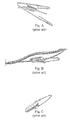
- a second type of assembly described in the French Patent 9,208,802 consists of a support element provided with a frustoconical longitudinal recess able to receive a core with a shape matching that of the recess formed by a pair of casings provided with a longitudinal seat inside which the conductor to be supported is inserted (see Fig. B).
- the main disadvantage of this second type of assembly lies in that the support element designed to clamp the pair of half-casings is formed as a single body and this makes the operation of clamping the pair of casings which retain the conductor less easy and slower, compared to the example illustrated in the previous type of assembly, in which the first inner pair of casings which retains the conductor is closed by a second outer pair of casings.
- a third type of assembly described in the patent Malico (US 4,872,626) has substantially the same limitations as those of the first type of assembly.
- this type of assembly is composed substantially of two longitudinal casings defining a frustoconical internal cavity inside which there is inserted a correspondingly shaped deformable core, said core also being composed of two half-casings which have formed inside them a seating designed to receive a conductor.
- An essential object of the present invention is therefore that of overcoming the drawbacks of systems of the known type, by providing an assembly for the overhead supporting of cables, which allows a plurality of overhead cables to be gripped and supported in a rapid and low-cost manner, without damaging them at all.
- a further object of the present invention is that of providing an assembly which is easy and practical to install, allowing in particular variation of the pressure to be exerted on the cables by means of use of an auxiliary device.
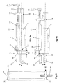
- the assembly in question which comprises substantially: a hollow body formed by a pair of semi-cylindrical half-casings provided with a rounded seat designed to receive an overhead cable and hinged with one another along a common longitudinal edge thereof; a closing device designed to clamp the casings together; a fastening member mounted on the closing device for connecting the assembly to a support pylon or pole.
- the aforementioned casings are each provided, in the region of respective free edges, with a longitudinal lip extending so as to project therefrom and tapering from a first end to a second end of the hollow body.
- These longitudinal lips form a single body with the respective casings and providing a guide onto which a sliding piece formed on the closing device may be inserted.
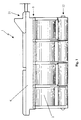
- substantially a hollow body 2 formed by a pair of substantialy semi-cylindrical casings 3, 4 which can be clamped together in the region of a free edge 5 thereof by a closing device 6.
- Each casing 3, 4 has internally a longitudinal seat 7 having affixed on the inside thereof a semi-cylindrical lining 8 on which a seating 9 designed to receive a cable 10 is formed.
- the support assembly 1 in question has been designed in particular to grip and support conductors 10 for telecommunications, which are electrically insulated, in such a way that these can be supported by respective standards 11 (poles or pylons made of wood, fibreglass, cement, etc.) without the aid of carrying cables.
- the two casings 3, 4 extend mainly in a longitudinal direction X and are hinged with one another along a common longitudinal edge 12 thereof.
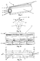
- the casings 3, 4 have a longitudinal lip 15 extending so as to project therefrom and tapering from a first end 16 to a second end 17 of the hollow body 2.
- the longitudinal lips 15 form a single body with the respective casings 3, 4, being able to be obtained advantageously by means of moulding from engineering polymers able to withstand the severest climatic stresses.
- the lips 15 are arranged alongside one another so as to form a guide 18 formed substantially as a dovetail (see Fig. 3a), which gradually tapers from the first end 16 to the second end 17 of the hollow body 2.
- the closing device 6 is provided with a sliding piece 19 having a longitudinal cavity 20 which is correspondingly shaped with respect to the guide 18 along which the sliding piece 19 is free to slide (see Figs. 5a, 5b). Insertion of the sliding piece 19 into the guide 18 causes gradual tightening of the casings 3, 4 against one another and hence a corresponding compressive action of the linings 8 on the conductor 10.
- the forward movement of the closing device 6 inside the guide 18 continues as far as an end locking position 21, where a rigid coupling between the closing device 6, the hollow body 2 and the conductor 10 is achieved.
- the linings 8 mentioned above consist of a deformable material (for example rubber) designed to increase the adherence between the casings 3, 4 and the conductor 10 as well as ensure uniform distribution of the pressure of the casings 3, 4 on the surface of the conductor itself.
- a deformable material for example rubber
- the internal surface of the linings 8 may have moreover an accentuated roughness so as to increase the coefficient of friction and hence improve the adherence thereof to the conductors 10.
- the longitudinal seats 7 have at their ends a perimetral edging 33 arranged in the transverse direction and designed to offset possible displacements between the linings 8 and the casings 3, 4 in particular when the conductor is tensioned.
- the guide 18 may have applied on it special indices 22 designed to indicate the presence exerted by the casings 3, 4 on the conductor 10 when there is a variation in the position assumed by the closing device 6 along the guide 18 (see Fig. 3c). In this way it is always possible to regulate the pressure which is to be exerted on the conductor 10.
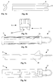
- the closing device 6 has mounted on it moreover a fastening member 23 which performs the function of connecting the support assembly to a fixed point of the line, such as, for example, a support pylon or pole 11.
- the fastening member 23 consists of a thin stainless steel rod which is bent in a ring shape and is incorporated in the closing device 6 during the moulding stage.
- the two materials from which the closing device 6 and the fastening member 23 are made have the same heat expansion coefficient and therefore, even in the event of substantial temperature variations, do not give rise to undesirable cracking or splintering phenomena.
- auxiliary device 24 for performing locking/releasing of the closing device 6 onto/from the hollow body 2 by means of end sliding (indicated by way of illustration as D in Figs. 9a and 9b) of the sliding piece 19 on the guide 18.
- the auxiliary device 24 consists of a mask which can be inserted onto the support assembly 1 in the region of the closing device 6. It has substantially the form of a rectangular frame which is elongated in the longitudinal direction X and has at a first end 25 a first projection 26 designed to rest against the closing device 6 at the first end 16 of the hollow body 2 when releasing of the closing device 6 from the hollow body 2 is performed (see Fig. 9a). The same projection 26 is moreover designed, once the auxiliary device 24 has been overturned on the closing device 6, to rest against the first end 16 of the hollow body 2 when locking of the closing device 6 is performed on the hollow body 2 (see Fig. 9b).
- a second projection 27, arranged on the second end 28 of the mask, has keyed onto it a screw 29 arranged parallel to the longitudinal direction X.
- the latter by means of screwing comes into abutment, at the second end 17 of the hollow body 2, respectively against the closing device 6 during the locking operation (see Fig. 9b) and against the hollow body 2 during the releasing operation (see Fig. 9a).
- the closing device 6 is mounted manually on the hollow body 10 by inserting the sliding piece 19 inside the guide 18 and thus performing a first constriction of the conductor 10.
- one of the two support assemblies 1 provided for each span has associated with it an easy-to-handle tensioning device 30 connected to the pole 11 by means of a chain 31 (see Fig. 7).
Applications Claiming Priority (4)
| Application Number | Priority Date | Filing Date | Title |
|---|---|---|---|
| ITTN960005 | 1996-05-20 | ||
| IT96TN000005A IT1289210B1 (it) | 1996-05-20 | 1996-05-20 | Modulo autostringente per supporto cavi aerei |
| ITVR970031 | 1997-04-11 | ||
| ITVR970031 IT1293949B1 (it) | 1997-04-11 | 1997-04-11 | Gruppo per il supporto aereo di cavi, in particolare per telecomunicazioni |
Publications (1)
| Publication Number | Publication Date |
|---|---|
| EP0809340A1 true EP0809340A1 (fr) | 1997-11-26 |
Family
ID=26332160
Family Applications (1)
| Application Number | Title | Priority Date | Filing Date |
|---|---|---|---|
| EP97830224A Withdrawn EP0809340A1 (fr) | 1996-05-20 | 1997-05-14 | Dispositif de support pour câbles aérien, en particulier câbles de télécommunication |
Country Status (2)
| Country | Link |
|---|---|
| EP (1) | EP0809340A1 (fr) |
| BR (1) | BR9703784A (fr) |
Cited By (9)
| Publication number | Priority date | Publication date | Assignee | Title |
|---|---|---|---|---|
| WO1999032916A1 (fr) * | 1997-12-19 | 1999-07-01 | Alcoa Fujikura Ltd. | Bride pivotante pour cable en fibre optique |
| EP0996209A1 (fr) * | 1998-10-19 | 2000-04-26 | OFFICINA FRATELLI BERTOLOTTI S.p.A. | Pince d'ancrage à boulons pour câble de ligne électrique aérienne |
| FR2789815A1 (fr) * | 1999-02-11 | 2000-08-18 | D App Et De Materiel Electr S | Pince d'ancrage, notamment pour cable isole multiconducteur a fibres optiques |
| WO2000075704A1 (fr) * | 1999-06-09 | 2000-12-14 | Tyco Electronics Raychem Nv | Mecanisme de detente pour fibres optiques |
| EP1914837A3 (fr) * | 2006-10-20 | 2009-11-04 | Tyco Electronics UK Ltd. | Connecteur électrique |
| CN102136708A (zh) * | 2011-01-25 | 2011-07-27 | 永固集团股份有限公司 | 平行集束型绝缘电缆耐张线夹 |
| WO2013150051A1 (fr) * | 2012-04-03 | 2013-10-10 | Tyco Electronics Raychem Bvba | Système et procédé de fixation de câble |
| JP5697292B1 (ja) * | 2014-02-18 | 2015-04-08 | Rtb株式会社 | ロープ装着具 |
| CZ307115B6 (cs) * | 2001-03-14 | 2018-01-24 | Ensto Sekko Oy | Kotvicí svorka pro ukončení nadzemního kabelu |
Citations (9)
| Publication number | Priority date | Publication date | Assignee | Title |
|---|---|---|---|---|
| FR2461383A1 (fr) * | 1979-07-09 | 1981-01-30 | Sicame Sa | Pince d'ancrage a coincement et fourrure elastique pour conducteurs divers |
| DE3123591A1 (de) * | 1981-06-13 | 1982-12-30 | Otto, Heinz, 5884 Halver | "abspannklemme" |
| EP0132208A1 (fr) * | 1983-06-15 | 1985-01-23 | MALICO : Société Anonyme | Pince d'ancrage pour câbles porteurs isolés à plusieurs conducteurs |
| GB2178602A (en) * | 1985-07-26 | 1987-02-11 | Pfisterer Elektrotech Karl | Insulated anchor or suspension clamp |
| DE3821653A1 (de) * | 1987-08-14 | 1989-02-23 | Herland Gmbh | Abspannklemme fuer kabel |
| US4872626A (en) * | 1986-11-06 | 1989-10-10 | Malico S.A. | Insulated anchoring clamp for insulated electric conductor equipped with a carrying cable |
| EP0579543A1 (fr) * | 1992-07-16 | 1994-01-19 | ETABLISSEMENTS DERANCOURT (Société à Responsabilité Limitée) | Pince d'ancrage pour câble électrique |
| US5308026A (en) * | 1992-03-09 | 1994-05-03 | Esmet, Inc. | Midline cable clamp construction |
| JPH0833172A (ja) * | 1994-07-11 | 1996-02-02 | Fujikura Ltd | 耐振型懸垂クランプ |
-
1997
- 1997-05-14 EP EP97830224A patent/EP0809340A1/fr not_active Withdrawn
- 1997-05-20 BR BR9703784A patent/BR9703784A/pt not_active Application Discontinuation
Patent Citations (9)
| Publication number | Priority date | Publication date | Assignee | Title |
|---|---|---|---|---|
| FR2461383A1 (fr) * | 1979-07-09 | 1981-01-30 | Sicame Sa | Pince d'ancrage a coincement et fourrure elastique pour conducteurs divers |
| DE3123591A1 (de) * | 1981-06-13 | 1982-12-30 | Otto, Heinz, 5884 Halver | "abspannklemme" |
| EP0132208A1 (fr) * | 1983-06-15 | 1985-01-23 | MALICO : Société Anonyme | Pince d'ancrage pour câbles porteurs isolés à plusieurs conducteurs |
| GB2178602A (en) * | 1985-07-26 | 1987-02-11 | Pfisterer Elektrotech Karl | Insulated anchor or suspension clamp |
| US4872626A (en) * | 1986-11-06 | 1989-10-10 | Malico S.A. | Insulated anchoring clamp for insulated electric conductor equipped with a carrying cable |
| DE3821653A1 (de) * | 1987-08-14 | 1989-02-23 | Herland Gmbh | Abspannklemme fuer kabel |
| US5308026A (en) * | 1992-03-09 | 1994-05-03 | Esmet, Inc. | Midline cable clamp construction |
| EP0579543A1 (fr) * | 1992-07-16 | 1994-01-19 | ETABLISSEMENTS DERANCOURT (Société à Responsabilité Limitée) | Pince d'ancrage pour câble électrique |
| JPH0833172A (ja) * | 1994-07-11 | 1996-02-02 | Fujikura Ltd | 耐振型懸垂クランプ |
Non-Patent Citations (1)
| Title |
|---|
| PATENT ABSTRACTS OF JAPAN vol. 096, no. 006 28 June 1996 (1996-06-28) * |
Cited By (14)
| Publication number | Priority date | Publication date | Assignee | Title |
|---|---|---|---|---|
| WO1999032916A1 (fr) * | 1997-12-19 | 1999-07-01 | Alcoa Fujikura Ltd. | Bride pivotante pour cable en fibre optique |
| US6135398A (en) * | 1997-12-19 | 2000-10-24 | Alcoa Fujikura Limited | Trunion clamp for optical fiber |
| EP0996209A1 (fr) * | 1998-10-19 | 2000-04-26 | OFFICINA FRATELLI BERTOLOTTI S.p.A. | Pince d'ancrage à boulons pour câble de ligne électrique aérienne |
| FR2789815A1 (fr) * | 1999-02-11 | 2000-08-18 | D App Et De Materiel Electr S | Pince d'ancrage, notamment pour cable isole multiconducteur a fibres optiques |
| KR100725678B1 (ko) * | 1999-06-09 | 2007-06-07 | 타이코 일렉트로닉스 레이켐 엔베 | 광섬유 부재용 멈춤쇠 장치 및 광섬유 오거나이저 트래이 |
| US6695491B1 (en) | 1999-06-09 | 2004-02-24 | Tyco Electronics Raychem N.V. | Detent for optical fibres |
| WO2000075704A1 (fr) * | 1999-06-09 | 2000-12-14 | Tyco Electronics Raychem Nv | Mecanisme de detente pour fibres optiques |
| CZ307115B6 (cs) * | 2001-03-14 | 2018-01-24 | Ensto Sekko Oy | Kotvicí svorka pro ukončení nadzemního kabelu |
| EP1914837A3 (fr) * | 2006-10-20 | 2009-11-04 | Tyco Electronics UK Ltd. | Connecteur électrique |
| CN102136708A (zh) * | 2011-01-25 | 2011-07-27 | 永固集团股份有限公司 | 平行集束型绝缘电缆耐张线夹 |
| CN102136708B (zh) * | 2011-01-25 | 2012-11-21 | 永固集团股份有限公司 | 平行集束型绝缘电缆耐张线夹 |
| WO2013150051A1 (fr) * | 2012-04-03 | 2013-10-10 | Tyco Electronics Raychem Bvba | Système et procédé de fixation de câble |
| JP5697292B1 (ja) * | 2014-02-18 | 2015-04-08 | Rtb株式会社 | ロープ装着具 |
| WO2015125220A1 (fr) * | 2014-02-18 | 2015-08-27 | Rtb株式会社 | Outil de montage de câble |
Also Published As
| Publication number | Publication date |
|---|---|
| BR9703784A (pt) | 1998-08-04 |
Similar Documents
| Publication | Publication Date | Title |
|---|---|---|
| US10095001B2 (en) | Spring assist cable clamps | |
| EP0809340A1 (fr) | Dispositif de support pour câbles aérien, en particulier câbles de télécommunication | |
| CA2454258A1 (fr) | Elements tendeurs composites et procede de fabrication associe | |
| AU667541B2 (en) | Cord grip arrangement | |
| KR101564300B1 (ko) | 송·배전용 철탑 현수 애자 | |
| WO1999032916A1 (fr) | Bride pivotante pour cable en fibre optique | |
| US5222701A (en) | Wall mounted support for holding articles | |
| GB2302457A (en) | Puller for attaching to the end of a cable | |
| US4373112A (en) | Cable holder | |
| US1758218A (en) | Electrical connecter | |
| KR101829671B1 (ko) | 가공배전선로 활선작업용 신축형 전선 커버 | |
| US10705301B2 (en) | Spring assist cable clamp | |
| CA1096025A (fr) | Colonnette de distribution d'electricite | |
| EP0696389B1 (fr) | Support pour un cable basse tension | |
| US20190056561A1 (en) | Sliding jaw drop clamp | |
| KR101829670B1 (ko) | 가공배전선로의 활선 작업용 애자 덮개 | |
| KR102349148B1 (ko) | 와이어 덕트 고정 장치 | |
| HU231108B1 (hu) | Behúzóeszköz | |
| CZ40698A3 (cs) | Závěsná svorka pro zavěšení vodičů vysokonapěťových volných kabelů nejméně 52 kV na nosnou konstrukci | |
| GB2178602A (en) | Insulated anchor or suspension clamp | |
| US6173103B1 (en) | Split open dead end | |
| MY104954A (en) | A sleeve of plastic sheet material for a cable termination, a cable splice or another cable portion freed from the cable sheet of electrical cables. | |
| GB2178909A (en) | Cable barrier gland | |
| ES2190100T3 (es) | Uniones para cables electricos y procedimiento para su fabricacion. | |
| KR101785718B1 (ko) | 배전용 케이블 클램핑장치 |
Legal Events
| Date | Code | Title | Description |
|---|---|---|---|
| PUAI | Public reference made under article 153(3) epc to a published international application that has entered the european phase |
Free format text: ORIGINAL CODE: 0009012 |
|
| AK | Designated contracting states |
Kind code of ref document: A1 Designated state(s): AT CH DE ES FR GB GR LI |
|
| AKX | Designation fees paid |
Free format text: AT CH DE ES FR GB GR LI |
|
| RBV | Designated contracting states (corrected) |
Designated state(s): AT CH DE ES FR GB GR LI |
|
| STAA | Information on the status of an ep patent application or granted ep patent |
Free format text: STATUS: THE APPLICATION IS DEEMED TO BE WITHDRAWN |
|
| 18D | Application deemed to be withdrawn |
Effective date: 19980527 |