EP0809211B1 - Method for radiography - Google Patents
Method for radiography Download PDFInfo
- Publication number
- EP0809211B1 EP0809211B1 EP97201434A EP97201434A EP0809211B1 EP 0809211 B1 EP0809211 B1 EP 0809211B1 EP 97201434 A EP97201434 A EP 97201434A EP 97201434 A EP97201434 A EP 97201434A EP 0809211 B1 EP0809211 B1 EP 0809211B1
- Authority
- EP
- European Patent Office
- Prior art keywords
- images
- ray
- image
- series
- dimensional
- Prior art date
- Legal status (The legal status is an assumption and is not a legal conclusion. Google has not performed a legal analysis and makes no representation as to the accuracy of the status listed.)
- Expired - Lifetime
Links
Images

Classifications
-
- G—PHYSICS
- G06—COMPUTING OR CALCULATING; COUNTING
- G06T—IMAGE DATA PROCESSING OR GENERATION, IN GENERAL
- G06T12/00—Tomographic reconstruction from projections
- G06T12/30—Image post-processing, e.g. metal artefact correction
-
- A—HUMAN NECESSITIES
- A61—MEDICAL OR VETERINARY SCIENCE; HYGIENE
- A61B—DIAGNOSIS; SURGERY; IDENTIFICATION
- A61B90/00—Instruments, implements or accessories specially adapted for surgery or diagnosis and not covered by any of the groups A61B1/00 - A61B50/00, e.g. for luxation treatment or for protecting wound edges
- A61B90/36—Image-producing devices or illumination devices not otherwise provided for
- A61B2090/364—Correlation of different images or relation of image positions in respect to the body
- A61B2090/367—Correlation of different images or relation of image positions in respect to the body creating a 3D dataset from 2D images using position information
-
- A—HUMAN NECESSITIES
- A61—MEDICAL OR VETERINARY SCIENCE; HYGIENE
- A61B—DIAGNOSIS; SURGERY; IDENTIFICATION
- A61B90/00—Instruments, implements or accessories specially adapted for surgery or diagnosis and not covered by any of the groups A61B1/00 - A61B50/00, e.g. for luxation treatment or for protecting wound edges
- A61B90/36—Image-producing devices or illumination devices not otherwise provided for
- A61B90/37—Surgical systems with images on a monitor during operation
- A61B2090/376—Surgical systems with images on a monitor during operation using X-rays, e.g. fluoroscopy
-
- A—HUMAN NECESSITIES
- A61—MEDICAL OR VETERINARY SCIENCE; HYGIENE
- A61B—DIAGNOSIS; SURGERY; IDENTIFICATION
- A61B34/00—Computer-aided surgery; Manipulators or robots specially adapted for use in surgery
- A61B34/20—Surgical navigation systems; Devices for tracking or guiding surgical instruments, e.g. for frameless stereotaxis
-
- Y—GENERAL TAGGING OF NEW TECHNOLOGICAL DEVELOPMENTS; GENERAL TAGGING OF CROSS-SECTIONAL TECHNOLOGIES SPANNING OVER SEVERAL SECTIONS OF THE IPC; TECHNICAL SUBJECTS COVERED BY FORMER USPC CROSS-REFERENCE ART COLLECTIONS [XRACs] AND DIGESTS
- Y10—TECHNICAL SUBJECTS COVERED BY FORMER USPC
- Y10S—TECHNICAL SUBJECTS COVERED BY FORMER USPC CROSS-REFERENCE ART COLLECTIONS [XRACs] AND DIGESTS
- Y10S378/00—X-ray or gamma ray systems or devices
- Y10S378/901—Computer tomography program or processor
Definitions
- the invention relates to an X-ray recording method in which a first imaging facility a series of two-dimensional x-rays is made and stored digitally, from which the examination object is made different perspectives is projected onto an X-ray image recorder.
- the invention relates to an arrangement for performing the Process.
- the disadvantage here is that the x-rays only show the vascular system, while the tissue in the Environment is not shown. In stereotactic examinations, however, it is the relative location of a structure relevant to the investigation, e.g. a tumor to be able to determine in relation to the vascular system.
- a reference frame - possibly in conjunction with Reference markers used - the one or those on the X-rays or the CT image are imaged so that the location of the anatomical to be examined Structures in relation to the reference frame or the reference markers exactly determined and results from the different images correlated with each other can be.
- the examiner gives in the three-dimensional CT image shows a point at which a biopsy should be performed and a Computer calculates the mechanical settings of a stereotactic Framework with which the biopsy point becomes the focus point of the stereotactic Frame can be moved.
- the horizontal and vertical Angle settings under which a biopsy needle is inserted, are shown with With the help of angiographic x-rays, which determined the Vascular points that are close to the path of the biopsy needle are digitized and placed in the Computer entered, which calculates the appropriate angle and displays.
- a disadvantage of this procedure is that the examiner relies on the calculations must leave the computer and no direct, three-dimensional impression of the Location of the biopsy path in relation to the vascular system.
- the object of the present invention is a method of the aforementioned Art so that the user an improved, quasi three-dimensional Impression of the location of the structure relevant to the diagnosis, e.g. a tumor, in relation to the anatomy shown in the x-rays (e.g. the Vascular system).
- the x-rays e.g. the Vascular system.
- a biopsy for example, he can do that himself determine the optimal biopsy path or an automatically specified biopsy path judge.
- a synthetic, two-dimensional projection image that calculated from the three-dimensional Image of a second imaging device represents extracted structure, with the same geometric parameters, with which this structure and e.g. the vascular system in generating the X-rays are projected.
- the structure is in the X-rays not visible due to their low contrast; however, in the calculated synthetic projection image the contrast with which the structure is represented can be specified as desired (a colored representation is also possible).
- the X-ray and the synthetic projection image related to each other correspond are combined to form an overlay, and these As a result, overlay images are displayed one after the other.
- the examiner gets a quasi three-dimensional impression of the Examination area, being the relative position of the extracted structure in with reference to the anatomy shown in the x-rays, e.g. the Vascular system.
- a preferred development of the invention provides that the second imaging Setting up an x-ray computer tomograph is used, being used for creation a three-dimensional image of the examination object a number of Tomograms are created from parallel slices. Basically, it is also possible to use a different modality for creating a three-dimensional image use, e.g. an MR device or an ultrasound device.
- a sequence of Stereo image pairs are played back two image sequences, both from the one sequence of the overlay images are derived, the two image sequences by a few Overlay images are offset from one another. Received with suitable playback the user then - for each individual overlay image - a stereoscopic one Image impression, although there is only one image sequence.
- suitable from the Sequence can be selected (e.g. so that the object from under 6 ° against each other represent staggered perspectives), then a stereoscopic impression arises, although the two image sequences from which the stereo image pairs are derived are not are independent of each other, but from the same sequence of overlay images are derived.
- a preferred development of the invention provides that to represent the Vascular course in a patient before taking the X-rays Contrast agent injection is used to generate a first series of X-rays, which represent the patient's vascular system filled with contrast medium. This is it is possible to visualize the vascular system. With such a vascular representation, achieve a further improvement in that in a short time Distance from the first series of x-rays another series of X-rays are taken that show the patient without contrast media represent that the corresponding x-rays of the two Series are subtracted from each other to generate difference images, and that the difference images and the synthetic images to generate the overlay images Projection images are superimposed on one another.
- the first imaging device is an X-ray image intensifier due to the usual curvature of the input screen of the X-ray image intensifier and distortion of the X-ray images due to the effect of the earth's magnetic field result.
- these are eliminated by a first Correction step for correcting those dependent on the X-ray image sensor Distortions using a first set of stored correction parameters the overlay step.
- the X-rays In an x-ray imaging system in which an x-ray emitter and the X-ray image recorders are attached to a C-arm, the X-rays also affected by the fact that the C-arm is not rigid, but under the influence of gravity and centrifugal forces, possibly through mechanical vibrations deformed. As a result, the shift or twist X-rays compared to the ideal case (same relative position of the X-ray emitter in relation to the X-ray image sensor in all perspectives). This affects the accuracy of the overlay images. Leave this eliminate themselves by a second correction step to correct the by Change in the relative position of the x-ray emitter in relation to the X-ray image dependent image transformation (image shift and Image rotation) using a second set of stored correction parameters the overlay step.
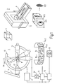
- Fig. 1, 1 is a first imaging device and 2 is a second imaging facility.
- the first imaging facility is used to create two-dimensional X-ray images of an examination object 3 located on a table 4, e.g. of a patient.
- the second imaging device is used to generate a three-dimensional image.
- a data record is used as a "three-dimensional image" referred to, the absorption distribution in the examination object 3 in one reproduces three-dimensional area and that of a number of two-dimensional Computer tomograms CT1, CT2 ... CTm of adjacent parallel ones Layers of the examination object is derived.
- the first imaging device 1 comprises a so-called circular arc C-arm 10 which is held on a tripod 11 only partially shown. It can the C-arm is pivoted on the one hand about a horizontal axis and by means of a Motor drive, not shown, in the direction of the double arrow 20 by e.g. Can be moved 180 ° around its center.
- On the C-arm 10 are a X-ray tube 12 and an X-ray image sensor 13 attached to each other are aligned that of an examination volume around the mentioned An X-ray can be taken around the center.
- One can A large number of x-rays are generated, e.g. 100 who the Examination volume from different - reproducible - angular positions (some are indicated by dashed lines) of the image recording system 12, 13.
- the x-ray image recorder 13 can be an x-ray image intensifier with a television chain connected to it, the output signals of which are digitized by an analog-digital converter 14 and stored in a memory 15, so that the entire series of x-ray recordings is stored at the end of the examination.
- These x-ray images can be processed by an image processing unit 16.
- the generated images (.... D i-1 , D i , D i + 1 , D i + 2 Vietnamese) can be displayed - individually or as an image sequence - on a monitor 18.
- the individual components of the imaging system 1 are controlled with the aid of a control unit 17.
- the empty images M are subtracted from the corresponding contrast images that were recorded from the same angular position (step 102), so that a sequence of difference images D 1 ... D i ... D n results that only for the different angular positions still represent the vascular system because the other anatomical structures are eliminated by the subtraction.
- difference images instead of the difference images, however, only contrast agent images (without subtracting empty images) can be used. In this case, more contrast medium must be injected; however, you can still see bone structures.
- CT1 Before or after the generation of these x-rays is made of the same anatomical region of the patient a series of computer tomograms CT1 ... CTm created the absorption distribution in adjacent parallel planes of the Represents examination region so that a three-dimensional "image" results, i.e. a data set showing the absorption distribution in a three-dimensional area identifies (method step 201). So that the image data from the different modalities are obtained, related to each other a frame of reference may be used in conjunction with Reference markers are used that are related to the examination region - e.g. the Skull of the patient - are fixed and in the X-rays or the Computer tomograms are also shown. You can in the X-rays or in the computer tomograms with the help of automatic Image processing methods are detected and as a coordinate system be used when it comes to image data of one modality Relate image data of the other modality. This is in detail document D2.
- a diagnostically relevant structure is created from the Computer tomograms extracted, e.g. a tumor or a specific region in the Brain (ventricle).
- This can be done interactively by the user, however automatic image processing methods are also possible that support this structure Extract segmentation (202).
- Extract segmentation (202) it's not just the shape and size of the structure known, but also their location in relation to a reference frame or coordinate system connected to the reference markers. In the simplest case it is enough extract even a geometric attribute from the structure, e.g. their Center point (center of gravity) or lines or simple geometrical bodies representing this Limit structure.
- Geometric distortions can result if the x-ray image pickup comprises an x-ray image intensifier which has a curved input screen and whose output screen image can be influenced by the earth's magnetic field.
- the difference images D 1 ... D n are subjected to a geometric transformation in step 103, the parameters of which are determined and stored in a preceding calibration method, in which a regular grating is preferably arranged in the beam path and its image is evaluated in an X-ray image , This is described in detail in document D1. If the x-ray image recorder has no such geometric distortions, this method step can be omitted.
- the C-arm is not absolutely rigid is. Rather, it deforms under the influence of gravity and centrifugal forces, so that the distance of the X-ray source from the image intensifier depends on the Can change the position of the C-arm in space. Furthermore, this deformation can As a result, the isocenter (which is on the X-ray tube with the center of the image sensor connecting central beam), with which is linked to the coordinate system relevant for the x-ray exposure moves and rotates from x-ray to x-ray. The result changes in the x-rays usually do not interfere, as long as you look at the x-rays for yourself. But if you Image data from different X-ray images with one another or with image data wants to relate the CT image to the achievable accuracy impaired.
- the correction carried out in method step 104 of the effects caused thereby Effects is based on the fact that the system 10, 11, 12, 13 (see FIG. 1) when rotating in the direction of the double arrow 20 in a reproducible manner deformed.
- the deformation can be carried out in a previous calibration process Suitable calibration bodies can be determined, and from them - for each one Angular position - derivable correction parameters are used to correct the in these X-rays were used for angular positions.
- This too Calibration and correction procedures are detailed in document D1 described. It can be omitted if the C-arm is so rigid that the Deformations cannot affect the X-rays.
- projection images of the extracted structure are generated, one for each difference image D 1 ... D i ... D n .
- FIG. 3 shows this for a single projection image, the projection center (corresponding to the X-ray emitter 12) being designated 120, the projection rays emanating therefrom being designated 121 and the extracted structure being designated 122.
- the projection image (which corresponds in its position to the X-ray image sensor 13) is denoted by P i .
- Such a projection image can be calculated in such a way that it is determined whether there is at least one volume element (voxel) of the extracted structure on a projection beam 121 leading to a pixel in the projection image P i .
- a suitable image value is assigned to the pixel; if not the image value 0. This is repeated for all pixels, so that a projection image P i results which represents a projection 124 of the structure. This is repeated for all angular positions of the system 12-13 in which x-rays or the differential images derived therefrom were generated.
- Each projection image P i generated in this way is assigned to an X-ray image or a differential image D i , the position of the projection center 120 and the projection image P; in relation to the extracted structure 122 are determined by the position of the x-ray emitter or the x-ray image recorder in relation to the real structure when the corresponding x-ray image is taken.
- the synthetic projection images generated in this way can represent the extracted structure with any desired contrast, but also in color. It is only a question of reproducing the anatomical details from the different images in a geometrically correct manner, but not with regard to the contrast.
- a synthetic projection image is generated in the projection step 105 for each x-ray image, in which the projected structure in the projection image has the same shape and position as the real structure in the - if necessary corrected - difference images D 1 ... D i . ..D n would have if it could be mapped there.
- the difference images D 1 ... D i ... D n which essentially depict the vascular system
- the synthetic projection images P 1 ... P i ... P n which are those from the CT Represent the image extracted structure, superimposed on each other, so that a sequence of superimposition images U 1 ... U i , .. U n (Fig. 4) is created, which reproduces both anatomical structures in a geometrically correct assignment.
- This sequence of images can be reproduced on the monitor in the subsequent method step 107, so that a quasi three-dimensional image impression is created, which considerably facilitates treatment planning, for example the specification of a biopsy path, for the introduction of a biopsy needle into the structure - or the assessment of a previously calculated biopsy path.
- the biopsy path can be set interactively with a three-dimensional cross (cursor).
- Distance measurements are possible with the aid of a static image reproduction (method step 108), two superimposition images (each with a different projection angle) being displayed. Volume measurements can also be carried out. The method is then ended.
- the synthetic projection images 105 were first calculated and saved, and only then were the individual overlay images generated. It is also possible, however, during the playback of an x-ray or to calculate the associated synthetic projection image of a difference image and the difference image and the projection image just calculated on the monitor 18 superimpose, even if the x-rays or those from them derived differential images can be reproduced relatively quickly in succession. It it is then not necessary to close all synthetic projection images beforehand calculate and only afterwards assign them to the difference images or X-rays overlap.
- a stereoscopic view is also possible, in which a pair of stereo images is reproduced at the same time, which can be viewed with the usual means. No separate x-rays have to be generated for this. Rather, it is sufficient to reproduce two superimposition images that represent the examination region from two angular positions that differ by approximately 6 ° - for example the superimposition images U i -1 and U i + 1 or the images U i and U i + 2 (cf. Fig. 4).
- This stereoscopic display not only facilitates the planning of a biopsy path but also the stereotactic measurements in the overlay images.
Landscapes
- Physics & Mathematics (AREA)
- General Physics & Mathematics (AREA)
- Engineering & Computer Science (AREA)
- Theoretical Computer Science (AREA)
- Apparatus For Radiation Diagnosis (AREA)
- Image Processing (AREA)
- Image Analysis (AREA)
- Analysing Materials By The Use Of Radiation (AREA)
Description
Die Erfindung betrifft ein Röntgenaufnahme-Verfahren, bei dem mit einer ersten bildgebenden Einrichtung eine Serie von zweidimensionalen Röntgenaufnahmen angefertigt und digital gespeichert wird, bei denen das Untersuchungsobjekt aus unterschiedlichen Perspektiven auf einen Röntgenbildaufnehmer projiziert wird. Außerdem bezieht sich die Erfindung auf eine Anordnung zur Durchführung des Verfahrens.The invention relates to an X-ray recording method in which a first imaging facility a series of two-dimensional x-rays is made and stored digitally, from which the examination object is made different perspectives is projected onto an X-ray image recorder. In addition, the invention relates to an arrangement for performing the Process.
Ein solches Verfahren und eine solche Anordnung sind bekannt aus einem Aufsatz von Koppe et al in Proceedings CAR - 95 Berlin, 1995 pp. 101-107 - im folgenden mit D1 bezeichnet. Bevorzugt wird dieses Verfahren zur Darstellung des Gefäßsystems verwendet, in das zuvor Kontrastmittel injiziert wurde. Grundsätzlich wären auch dreidimensionale Darstellungen des Gefäßsystems möglich, z.B. mit MR- oder CT-Aufnahmen. Doch ist es damit noch nicht möglich, das Gefäßsystem mit so hoher räumlicher Auflösung zu rekonstruieren, wie es bei verschiedenen medizinischen Untersuchungen erforderlich ist. Bei dem eingangs beschriebenen Verfahren ergibt sich demgegenüber eine hohe räumliche Auflösung, und es entsteht ein quasi dreidimensionaler räumlicher Eindruck, wenn die Röntgenaufnahmen in schneller Folge nacheinander wiedergegeben werden. Nachteilig dabei ist aber, daß die Röntgenaufnahmen nur das Gefäßsystem zeigen, während das Gewebe in der Umgebung nicht dargestellt wird. Bei stereotaktischen Untersuchungen ist es aber erforderlich, die relative Lage einer für die Untersuchung relevanten Struktur, z.B. eine Tumors, in bezug auf das Gefäßsystem bestimmen zu können.Such a method and such an arrangement are known from an article by Koppe et al in Proceedings CAR - 95 Berlin, 1995 pp. 101-107 - hereinafter designated D1. This method is preferred for displaying the Vascular system used, in which contrast medium was previously injected. in principle three-dimensional representations of the vascular system would also be possible, e.g. With MR or CT images. But it is not yet possible for the vascular system to reconstruct with as high spatial resolution as it is with different medical examinations is required. With the above In contrast, the process results in a high spatial resolution, and it arises a quasi three-dimensional spatial impression when the x-rays in can be played back in quick succession. The disadvantage here is that the x-rays only show the vascular system, while the tissue in the Environment is not shown. In stereotactic examinations, however, it is the relative location of a structure relevant to the investigation, e.g. a tumor to be able to determine in relation to the vascular system.
Zu diesem Zweck ist es aus einer weiteren Veröffenlichung (D2) von Kelly et al in "Neurosurgery", Vol. 14, Nr. 2, 1984 bekannt, einerseits mittels einer Röntgen-Angiographie-Einrichtung Stereobildpaare zu erstellen, die das Gefäßsystem von vorne bzw. von der Seite zeigen und andererseits von der gleichen Region des Untersuchungsobjektes mittels eines Computertomographen ein dreidimensionales Bild zu erstellen. Um die Befunde in den zweidimensionalen Röntgenaufnahmen einerseits und dem dreidimensionalen CT-Bild andererseits einander zuordnen zu können, wird dabei ein Referenzrahmen - gegebenenfalls in Verbindung mit Referenzmarkern verwendet - der bzw. die auf den Röntgenaufnahmen bzw. dem CT-Bild abgebildet werden, so daß die Lage der zu untersuchenden anatomischen Strukturen in bezug auf den Referenzrahmen bzw. die Referenzmarker genau bestimmt und Befunde aus den verschiedenen Abbildungen miteinander korreliert werden können.For this purpose, it is from a further publication (D2) by Kelly et al in "Neurosurgery", Vol. 14, No. 2, 1984 known, on the one hand by means of a X-ray angiography facility to create stereo image pairs covering the vascular system point from the front or from the side and on the other hand from the same region of the A three-dimensional object to be examined by means of a computer tomograph Create image. To the findings in the two-dimensional X-rays on the one hand and the three-dimensional CT image on the other hand a reference frame - possibly in conjunction with Reference markers used - the one or those on the X-rays or the CT image are imaged so that the location of the anatomical to be examined Structures in relation to the reference frame or the reference markers exactly determined and results from the different images correlated with each other can be.
Bei dem bekannten Verfahren gibt der Untersucher in dem dreidimensionalen CT-Bild einen Punkt vor, in dem eine Biopsie durchgeführt werden soll, und ein Computer berechnet daraus die mechanischen Einstellungen eines stereotaktischen Rahmens, mit denen der Biopsiepunkt in den Fokuspunkt des stereotaktischen Rahmens gerückt werden kann. Die horizontalen und vertikalen Winkeleinstellungen, unter denen eine Biopsienadel eingeführt wird, werden mit Hilfe der angiographischen Röntgenaufnahmen bestimmt, bei denen die Gefäßpunkte, die dicht am Pfad der Biopsienadel liegen, digitalisiert und in den Computer eingegeben werden, der daraus die geeigneten Winkel berechnet und anzeigt.In the known method, the examiner gives in the three-dimensional CT image shows a point at which a biopsy should be performed and a Computer calculates the mechanical settings of a stereotactic Framework with which the biopsy point becomes the focus point of the stereotactic Frame can be moved. The horizontal and vertical Angle settings, under which a biopsy needle is inserted, are shown with With the help of angiographic x-rays, which determined the Vascular points that are close to the path of the biopsy needle are digitized and placed in the Computer entered, which calculates the appropriate angle and displays.
Nachteilig bei dieser Prozedur ist, daß der Untersucher sich auf die Berechnungen des Computers verlassen muß und keinen direkten, dreidimensionalen Eindruck der Lage des Biopsiepfades in bezug auf das Gefäßsystem vermittelt bekommt.A disadvantage of this procedure is that the examiner relies on the calculations must leave the computer and no direct, three-dimensional impression of the Location of the biopsy path in relation to the vascular system.
Aufgabe der vorliegenden Erfindung ist es, ein Verfahren der eingangs genannten Art so auszugestalten, daß der Benutzer einen verbesserten, quasi dreidimensionalen Eindruck von der Lage der für die Diagnose relevanten Struktur, z.B. eines Tumors, in bezug auf die in den Röntgenaufnahmen dargestellte Anatomie (z.B. das Gefäßsystem) erhält. Für eine Biopsie beispielsweise kann er dann selbst den optimalen Biopsiepfad ermitteln oder einen automatisch vorgegebenen Biopsiepfad beurteilen.The object of the present invention is a method of the aforementioned Art so that the user an improved, quasi three-dimensional Impression of the location of the structure relevant to the diagnosis, e.g. a tumor, in relation to the anatomy shown in the x-rays (e.g. the Vascular system). For a biopsy, for example, he can do that himself determine the optimal biopsy path or an automatically specified biopsy path judge.
Diese Aufgabe wird erfindungsgemäß gelöst durch die folgenden Verfahrensschritte
Bei der Erfindung wird also für jede Röntgenaufnahme ein synthetisches, zweidimensionales Projektionsbild berechnet, das die aus dem dreidimensionalen Bild einer zweiten bildgebenden Einrichtung (die ein Computertomograph sein kann) extrahierte Struktur darstellt, und zwar mit den gleichen geometrischen Parametern, mit denen diese Struktur und z.B. das Gefäßsystem bei der Erzeugung der Röntgenaufnahmen projiziert wird. In den Röntgenaufnahmen ist die Struktur wegen ihres geringen Kontrastes nicht sichtbar; jedoch kann in dem berechneten synthetischen Projektionsbild der Kontrast, mit dem die Struktur dargestellt wird, beliebig vorgegeben werden (es ist auch eine farbige Darstellung möglich). Die Röntgenaufnahme und das synthetische Projektionsbild, die zueinander korrespondieren, werden zu einem Überlagerungsbild kombiniert, und diese Überlagerungsbilder werden als Folge nacheinander wiedergeben. Der Untersucher bekommt dadurch einen quasi dreidimensionalen Eindruck des Untersuchungsbereichs, wobei er die relative Lage der extrahierten Struktur in bezug auf die in den Röntgenaufnahmen dargestellte Anatomie, z.B. das Gefäßsystem, erkennen kann.In the invention, a synthetic, two-dimensional projection image that calculated from the three-dimensional Image of a second imaging device (which can be a computer tomograph) represents extracted structure, with the same geometric parameters, with which this structure and e.g. the vascular system in generating the X-rays are projected. The structure is in the X-rays not visible due to their low contrast; however, in the calculated synthetic projection image the contrast with which the structure is represented can be specified as desired (a colored representation is also possible). The X-ray and the synthetic projection image related to each other correspond, are combined to form an overlay, and these As a result, overlay images are displayed one after the other. The examiner gets a quasi three-dimensional impression of the Examination area, being the relative position of the extracted structure in with reference to the anatomy shown in the x-rays, e.g. the Vascular system.
Eine bevorzugte Weiterbildung der Erfindung sieht vor, daß als zweite bildgebende Einrichtung ein Röntgen-Computertomograph verwendet wird, wobei zur Erstellung eines dreidimensionalen Bildes von dem Untersuchungsobjekt eine Anzahl von Tomogrammen von parallelen Schichten erstellt wird. Grundsätzlich ist es aber auch möglich, für die Erstellung eines dreidimensionalen Bildes eine andere Modalität zu benutzen, z.B. ein MR-Gerät oder ein Ultraschallgerät.A preferred development of the invention provides that the second imaging Setting up an x-ray computer tomograph is used, being used for creation a three-dimensional image of the examination object a number of Tomograms are created from parallel slices. Basically, it is also possible to use a different modality for creating a three-dimensional image use, e.g. an MR device or an ultrasound device.
In weiterer Ausgestaltung der Erfindung ist vorgesehen, daß zur Erzeugung einer Folge von Stereo-Bildpaaren zwei Bild-Folgen wiedergegeben werden, die beide aus der einen Folge der Überlagerungsbilder abgeleitet werden, wobei die beiden Bildfolgen um einige Überlagerungsbilder gegeneinander versetzt sind. Bei geeigneter Wiedergabe erhält der Benutzer dann - für jedes einzelne Überlagerungsbild - einen stereoskopischen Bildeindruck, obwohl nur eine einzige Bildfolge existiert. Wenn die beiden Überlagerungsbilder, die zusammen ein Stereobildpaar darstellen, geeignet aus der Folge ausgewählt werden (z.B. so, daß sie das Objekt aus unter 6° gegeneinander versetzten Perspektiven darstellen), dann entsteht ein stereoskopischer Eindruck, obwohl die beiden Bildfolgen, aus denen die Stereobildpaare abgeleitet werden, nicht voneinander unabhängig sind, sondern aus der gleichen Folge von Überlagerungsbildern abgeleitet sind. Grundsätzlich ist es aber auch möglich, zwei getrennte Bildfolgen zu erzeugen, die den Untersuchung sbereich mit unterschiedlicher Projektionsgeometrie abbilden.In a further embodiment of the invention it is provided that for generating a sequence of Stereo image pairs are played back two image sequences, both from the one sequence of the overlay images are derived, the two image sequences by a few Overlay images are offset from one another. Received with suitable playback the user then - for each individual overlay image - a stereoscopic one Image impression, although there is only one image sequence. If the two Overlay images that together represent a stereo image pair, suitable from the Sequence can be selected (e.g. so that the object from under 6 ° against each other represent staggered perspectives), then a stereoscopic impression arises, although the two image sequences from which the stereo image pairs are derived are not are independent of each other, but from the same sequence of overlay images are derived. Basically, it is also possible to have two separate ones Generate image sequences that cover the examination area with different Show projection geometry.
Eine bevorzugte Weiterbildung der Erfindung sieht vor, daß zur Darstellung des Gefäßverlaufs bei einem Patienten vor der Anfertigung der Röntgenaufnahmen eine Kontrastmittelinjektion erfolgt zur Erzeugung einer ersten Serie von Röntgenaufnahmen, die das mit Kontrastmittel gefüllte Gefäßsystem des Patienten darstellen. Dadurch ist es möglich, das Gefäßsystem darzustellen. Bei einer solchen Gefäßdarstellung läßt sich eine weitere Verbesserung dadurch erreichen, daß in geringem zeitlichen Abstand von der ersten Serie von Röntgenaufnahmen eine weitere Serie von Röntgenaufnahmen angefertigt wird, die den Patienten ohne Kontrastmittel darstellen, daß die zueinander korrespondierenden Röntgenaufnahmen der beiden Serien zur Erzeugung von Differenzbildern voneinander subtrahiert werden, und daß zur Erzeugung der Überlagerungsbilder die Differenzbilder und die synthetischen Projektionsbilder einander überlagert werden.A preferred development of the invention provides that to represent the Vascular course in a patient before taking the X-rays Contrast agent injection is used to generate a first series of X-rays, which represent the patient's vascular system filled with contrast medium. This is it is possible to visualize the vascular system. With such a vascular representation, achieve a further improvement in that in a short time Distance from the first series of x-rays another series of X-rays are taken that show the patient without contrast media represent that the corresponding x-rays of the two Series are subtracted from each other to generate difference images, and that the difference images and the synthetic images to generate the overlay images Projection images are superimposed on one another.
Ein wichtige Voraussetzung für quantitative Messungen an den Überlagerungsbildern ist, daß diese die aus den beiden bildgebenden Einrichtungen erhaltenen anatomischen Strukturen korrekt darstellen. Wenn der Röntgenbildaufnehmer der ersten bildgebenden Einrichtung jedoch ein Röntgenbildverstärker ist, können sich aufgrund der üblichen Krümmung des Eingangsschirms des Röntgenbildverstärkers sowie durch die Wirkung des Erdmagnetfeldes Verzerrungen der Röntgenaufnahmen ergeben. Diese werden in Ausgestaltung der Erfindung beseitigt durch einen ersten Korrekturschritt zur Korrektur der von dem Röntgenbildaufnehmers abhängigen Verzerrungen mit Hilfe eines ersten Satzes gespeicherter Korrekturparameter vor dem Überlagerungsschritt.An important prerequisite for quantitative measurements on the overlay images is that these are obtained from the two imaging devices Display anatomical structures correctly. If the X-ray imager is the However, the first imaging device is an X-ray image intensifier due to the usual curvature of the input screen of the X-ray image intensifier and distortion of the X-ray images due to the effect of the earth's magnetic field result. In an embodiment of the invention, these are eliminated by a first Correction step for correcting those dependent on the X-ray image sensor Distortions using a first set of stored correction parameters the overlay step.
Bei einem Röntgenaufnahmesystem, bei dem ein Röntgenstrahler und der Röntgenbildaufnehmer an einem C-Bogen befestigt sind, werden die Röntgenaufnahmen auch dadurch beeinflußt, daß der C-Bogen nicht starr ist, sondern sich unter dem Einfluß der Schwerkraft und der Fliehkräfte, ggf auch durch mechanische Schwingungen verformt. Dadurch verschieben bzw. verdrehen sich die Röntgenaufnahmen gegnüber dem Idealfall (gleiche relative Lage des Röntgenstrahlers in Bezug auf den Röntgenbildaufnehmer in allen Pespektiven). Dadurch wird die Genauigkeit der Überlagerungsbilder beeinträchtigt. Diese lassen sich beseitigen durch einen zweiten Korrekturschritt zur Korrektur der durch die Änderung der relativen Position des Röntgenstrahlers in Bezug auf den Röntgenbildaufnehmer abhängigen Bildtransformation (Bildverschiebung und Bilddrehung) mit Hilfe eines zweiten Satzes gespeicherter Korrekturparameter vor dem Überlagerungsschritt.In an x-ray imaging system in which an x-ray emitter and the X-ray image recorders are attached to a C-arm, the X-rays also affected by the fact that the C-arm is not rigid, but under the influence of gravity and centrifugal forces, possibly through mechanical vibrations deformed. As a result, the shift or twist X-rays compared to the ideal case (same relative position of the X-ray emitter in relation to the X-ray image sensor in all perspectives). This affects the accuracy of the overlay images. Leave this eliminate themselves by a second correction step to correct the by Change in the relative position of the x-ray emitter in relation to the X-ray image dependent image transformation (image shift and Image rotation) using a second set of stored correction parameters the overlay step.
Eine Anordnung zur Durchführung des erfindungsgemäßen Verfahrens weist eine
erste bildgebende Einrichtung auf, die einen Röntgenstrahler und einen
Röntgenbildaufnehmer umfaßt, die zur Anfertigung einer Serie von
zweidimensionalen Röntgenaufnahmen, bei denen ein Untersuchungsobjekt aus
unterschiedlichen Perspektiven auf den Röntgenbildaufnehmer projiziert wird, in
Bezug auf ein Untersuchungsobjekt verstellbar sind, mit Mitteln zum Speichern der
Röntgenaufnahmen und mit programmierbaren Bildverarbeitungsmitteln, die so
programmiert sind, daß folgende Bildverarbeitungsoperationen durchgeführt werden:
Die Erfindung wird nachstehend anhand der Zeichnungen näher erläutert. Es zeigen:
In Fig. 1 ist mit 1 eine erste bildgebende Einrichtung und mit 2 eine zweite bildgebende Einrichtung bezeichnet. Um die Bilder der ersten und der zweiten bildgebenden Einrichtung - bzw aus diesen Bildern abgeleitete Daten zueinander in Beziehung setzen zu können, wird in bekannter Weise ein Referenzrahmen 5 benutzt, der in den Bildern beider Einrichtungen mit abgebildet wird, ggf in Verbindung mit kugelförmigen Referenzmarkern. Grundsätzlich können diese Bilder aber auch anhand charkteristischer anatomischer Strukturen korreliert werden, wenn diese mit Hilfe geeigneter Bildverarbeitungsverfahren detektiert werden.In Fig. 1, 1 is a first imaging device and 2 is a second imaging facility. To the pictures of the first and the second imaging device - or data derived from these images to one another in To be able to set a relationship becomes a reference frame 5 in a known manner used, which is also shown in the pictures of both institutions, possibly in Connection with spherical reference markers. Basically, these pictures but can also be correlated using characteristic anatomical structures if these are detected with the aid of suitable image processing methods.
Die erste bildgebende Einrichtung dient der Erstellung zweidimensionaler
Röntgenaufnahmen eines auf einem Tisch 4 befindlichen Untersuchungsobjektes 3,
z.B. eines Patienten. Die zweite bildgebende Einrichtung dient zur Erzeugung eines
dreidimensionalen Bildes. Als "dreidimensionales Bild" wird dabei ein Datensatz
bezeichnet, der die Absorptionsverteilung in dem Untersuchungsobjekt 3 in einem
dreidimensionalen Bereich wiedergibt und der aus einer Anzahl zweidimensionaler
Computertomogramme CT1, CT2 ... CTm von nebeneinanderliegenden parallelen
Schichten des Untersuchungsobjektes abgeleitet wird.The first imaging facility is used to create two-dimensional
X-ray images of an
Die erste bildgebende Einrichtung 1 umfaßt einen kreisbogenförmigen, sogenannten
C-Bogen 10 der an einem nur teilweise dargestellten Stativ 11 gehaltert ist. Dabei kann
der C-Bogen einerseits um eine waagerechte Achse geschwenkt und mittels eines
nicht näher dargestellten Motorantriebs in Richtung des Doppelpfeiles 20 um z.B.
180° um seinen Mittelpunkt bewegt werden. An dem C-Bogen 10 sind ein
Röntgenstrahler 12 und ein Röntgenbildaufnehmer 13 befestigt, die so aufeinander
ausgerichtet sind, daß von einem Untersuchungsvolumen um den erwähnten
Mittelpunkt herum eine Röntgenaufnahme angefertigt werden kann. Dabei kann eine
Vielzahl von Röntgenaufnahmen erzeugt werden, z.B. 100, die das
Untersuchungsvolumen aus verschiedenen - reproduzierbaren - Winkelpositionen
(einige sind gestrichelt angedeutet) des Bildaufnahmesystems 12, 13 abbilden.The
Der Röntgenbildaufnehmer 13 kann einen Röntgenbildverstärker mit einer daran
angeschlossenen Fernsehkette sein, deren Ausgangssignale von einem
Analog-Digital-Wandler 14 digitalisiert und in einem Speicher 15 gespeichert
werden, so daß am Ende der Untersuchung die gesamte Röntgenaufnahmeserie
gespeichert ist. Diese Röntgenaufnahmen können von einer Bildverarbeitungseinheit
16 verarbeitet werden. Die erzeugten Bilder (....Di-1, Di, Di+1, Di+2 .....) können -
einzeln oder als Bildfolge - auf einem Monitor 18 dargestellt werden. Die Steuerung
der einzelnen Komponenten des bildgebenden Systems 1 erfolgt mit Hilfe einer
Steuereinheit 17.The
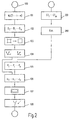
In Fig. 2 ist die Folge der Verfahrensschritte für die beiden bildgebenden Systeme dargestellt. Nach der Initialisierung (100) des ersten bildgebenden Systems wird - nach einer Kontrastmittelinjektion - eine Folge von n Röntgenaufnahmen erstellt (z.B. n=100), die das Untersuchungsobjekt und die darin befindlichen, mit Kontrastmittel gefüllten Blutgefäße darstellen (Schritt 101). Davor - oder danach - wird eine weitere Serie von Röntgenaufnahmen M erstellt, die dasselbe Objekt unter denselben Perspektiven darstellen wie die Röntgenaufnahmen C - die jedoch das Gefäßsystem nicht darstellen (weil entweder das Kontrastmittel noch nicht injiziert ist oder das Kontrastmittel sich schon so weit verteilt hat, daß es im Bild nicht mehr sichtbar wird).2 shows the sequence of process steps for the two imaging systems shown. After the initialization (100) of the first imaging system - after a contrast medium injection - a sequence of n X-ray images taken (e.g. n = 100) that the object to be examined and the objects it contains Represent contrast-filled blood vessels (step 101). Before - or after - Another series of X-ray images M is created, which under the same object represent the same perspectives as the X-ray images C - but that Do not visualize the vascular system (because either the contrast medium has not yet been injected or the contrast medium has already spread so far that it no longer appears in the image becomes visible).
Anschließend werden die Leeraufnahmen M von den korrespondierenden Kontrastbildern, die aus derselben Winkelposition aufgenommen wurden, subtrahiert (Schritt 102), so daß sich eine Folge von Differenzbildern D1...Di...Dn ergibt, die für die verschiedenen Winkelpositionen nur noch das Gefäßsystem darstellen, weil die anderen anatomischen Strukturen durch die Subtraktion eliminiert werden. - Anstelle der Differenzbilder können aber auch lediglich Kontrastmittelaufnahmen (ohne Subtraktion von Leeraufnahmen) verwendet werden. In diesem Fall muß mehr Kontrastmittel injiziert werden; man erkennt dann jedoch auch noch Knochenstrukturen.Subsequently, the empty images M are subtracted from the corresponding contrast images that were recorded from the same angular position (step 102), so that a sequence of difference images D 1 ... D i ... D n results that only for the different angular positions still represent the vascular system because the other anatomical structures are eliminated by the subtraction. - Instead of the difference images, however, only contrast agent images (without subtracting empty images) can be used. In this case, more contrast medium must be injected; however, you can still see bone structures.
Vor oder nach der Erzeugung dieser Röntgenaufnahmen wird von derselben anatomischen Region des Patienten eine Serie von Computertomogrammen CT1...CTm erstellt, die die Absorptionsverteilung in benachbarten parallelen Ebenen der Untersuchungsregion darstellt, so daß sich ein dreidimensionales "Bild" ergibt, d.h. ein Datensatz, der die Absorptionsverteilung in einem dreidimensionalen Bereich kennzeichnet (Verfahrensschritt 201). Damit die Bilddaten, die aus den verschiedenen Modalitäten gewonnen werden, zueinander in Beziehung gesetzt werden können, wird ein Referenzrahmen gegebenenfalls in Verbindung mit Referenzmarkern benutzt, die bezüglich der Untersuchungsregion - z.B. dem Schädel des Patienten - fixiert sind und in den Röntgenaufnahmen bzw. den Computertomogrammen mit abgebildet werden. Sie können in den Röntgenaufnahmen bzw. in den Computertomogrammen mit Hilfe automatischer Bildverarbeitungsverfahren detektiert werden und als Koordinatensystem herangezogen werden, wenn es darum geht, Bilddaten der einen Modalität zu Bilddaten der anderen Modalität in Beziehung zu setzen. Dies ist im einzelnen in dem Dokument D2 beschrieben.Before or after the generation of these x-rays is made of the same anatomical region of the patient a series of computer tomograms CT1 ... CTm created the absorption distribution in adjacent parallel planes of the Represents examination region so that a three-dimensional "image" results, i.e. a data set showing the absorption distribution in a three-dimensional area identifies (method step 201). So that the image data from the different modalities are obtained, related to each other a frame of reference may be used in conjunction with Reference markers are used that are related to the examination region - e.g. the Skull of the patient - are fixed and in the X-rays or the Computer tomograms are also shown. You can in the X-rays or in the computer tomograms with the help of automatic Image processing methods are detected and as a coordinate system be used when it comes to image data of one modality Relate image data of the other modality. This is in detail document D2.
Im nächsten Verfahrensschritt 202 wird eine diagnostisch relevante Struktur aus den
Computertomogrammen extrahiert, z.B. ein Tumor oder eine bestimmte Region im
Gehirn (Ventrikel). Dies kann interaktiv durch den Benutzer erfolgen, jedoch sind
auch automatische Bildverarbeitungsverfahren möglich, die diese Struktur durch
Segmentierung extrahieren (202). Danach ist nicht nur Form und Größe der Struktur
bekannt, sondern auch ihre Lage in Bezug auf ein mit dem Referenzrahmen bzw.
den Referenzmarkern verbundenes Koordinatensystem. Im einfachsten Fall genügt
es, von der Struktur auch nur ein geometrisches Attribut zu extrahieren, z.B. ihren
Mittelpunkt (Schwerpunkt) oder Linien oder einfache geometrische Körper, die diese
Struktur begrenzen.In the
Bevor diese Struktur mit den Röntgenaufnahmen in Verbindung gebracht wird, ist es
in manchen Fällen noch erforderlich, die Röntgenaufnahmen zu korrigieren bzw. zu
kalibrieren, um den realen Verhältnissen bei der Röntgenaufnahme Rechnung zu
tragen. So können sich geometrische Verzerrungen ergeben, wenn der
Röntgenbildaufnehmer einen Röntgenbildverstärker umfaßt, der einen gekrümmten
Eingangsschirm aufweist und dessen Ausgangsschirmbild von dem Erdmagnetfeld
beeinflußt werden kann. Zur Beseitigung dieser Verzerrungen werden im Schritt 103
die Differenzbilder D1...Dn einer geometrischen Transformation unterzogen, deren
Parameter in einem vorangehenden Kalibrierverfahren ermittelt und gespeichert
sind, bei dem vorzugsweise ein regelmäßiges Gitter im Strahlengang angeordnet und
seine Abbildung in einer Röntgenaufnahme ausgewertet wird. Im einzelnen ist dies
in dem Dokument D1 beschrieben.
Wenn der Röntgenbildaufnehmer keine solchen geometrischen Verzerrungen
aufweist, kann dieser Verfahrensschritt entfallen.Before this structure is associated with the x-rays, in some cases it is still necessary to correct or calibrate the x-rays in order to take into account the real conditions in the x-ray. Geometric distortions can result if the x-ray image pickup comprises an x-ray image intensifier which has a curved input screen and whose output screen image can be influenced by the earth's magnetic field. In order to eliminate these distortions, the difference images D 1 ... D n are subjected to a geometric transformation in
Weitere Faktoren, die die Genauigkeit des erfindungsgemäßen Verfahrens beeinträchtigen können, ergeben sich daraus, daß der C-Bogen nicht absolut starr ist. Er verformt sich vielmehr unter dem Einfluß der Schwerkraft und der Fliehkräfte, so daß sich der Abstand des Röntgenstrahlers von dem Bildverstärker je nach der Lage des C-Bogens im Raum ändern kann. Weiterhin kann diese Verformung zur Folge haben, daß sich das Isozentrum (welches sich auf dem den Röntgenstrahler mit dem Mittelpunkt des Bildaufnehmers verbindenden Zentralstrahl befindet), mit dem das für die Röntgenaufnahme relevante Koordinatensystem verknüpft ist, sich von Röntgenaufnahme zu Röntgenaufnahme verschiebt und dreht. Die dadurch bewirkten Veränderungen der Röntgenaufnahmen stören normalerweise nicht, solange man die Röntgenaufnahmen für sich allein betrachtet. Wenn man aber Bilddaten aus verschiedenen Röntgenaufnahmen miteinander oder mit Bilddaten aus dem CT-Bild in Beziehung setzen will, wird dadurch die erzielbare Genauigkeit beeinträchtigt.Other factors affecting the accuracy of the method according to the invention can result from the fact that the C-arm is not absolutely rigid is. Rather, it deforms under the influence of gravity and centrifugal forces, so that the distance of the X-ray source from the image intensifier depends on the Can change the position of the C-arm in space. Furthermore, this deformation can As a result, the isocenter (which is on the X-ray tube with the center of the image sensor connecting central beam), with which is linked to the coordinate system relevant for the x-ray exposure moves and rotates from x-ray to x-ray. The result changes in the x-rays usually do not interfere, as long as you look at the x-rays for yourself. But if you Image data from different X-ray images with one another or with image data wants to relate the CT image to the achievable accuracy impaired.
Die im Verfahrensschritt 104 durchgeführte Korrektur der dadurch bewirkten
Effekte basiert auf der Tatsache, daß sich das System 10, 11, 12, 13 (vergl. Fig. 1)
bei einer Rotation in Richtung des Doppelpfeiles 20 in reproduzierbarer Weise
verformt. Die Verformung kann in einem vorangehenden Kalibrierverfahren mit
Hilfe geeigneter Kalibrierkörper ermittelt werden, und die daraus - für jede einzelne
Winkelposition - ableitbaren Korrekturparameter werden zur Korrektur der in diesen
Winkelpositionen erzeugten Röntgenaufnahmen herangezogen. Auch dieses
Kalibrier- und Korrekturverfahren ist im einzelnen in dem Dokument D1
beschrieben. Es kann entfallen, wenn der C-Bogen so starr ist, daß sich die
Verformungen nicht auf die Röntgenaufnahmen auswirken können.The correction carried out in
Im nächsten Verfahrensschritt 105 werden Projektionsbilder der extrahierten
Struktur erzeugt, und zwar eines für jedes Differenzbild D1...Di...Dn. Fig. 3 stellt
dies für ein einziges Projektionsbild dar, wobei das der (zu dem Röntgenstrahler 12
korrespondierende) Projektionszentrum mit 120, die davon ausgehenden
Projektionstrahlen mit 121 und die extrahierte Struktur mit 122 bezeichnet sind. Das
(in seiner Lage mit dem Röntgenbildaufnehmer 13 korrespondierende)
Projektionsbild ist mit Pi bezeichnet. Die Berechnung eines solchen Projektionsbildes
kann so erfolgen, daß ermittelt wird, ob sich auf einem zu einem Bildpunkt im
Projektionsbild Pi führenden Projektionstrahl 121 mindestens ein Volumenelement
(voxel) der extrahierten Struktur befindet. Ist dies der Fall, wird dem Bildpunkt ein
geigneter Bildwert zugeordnet; wenn nicht der Bildwert 0. Dies wird für alle
Bildpunkte wiederholt, sodaß sich ein Projektionsbild Pi ergibt, das eine Projektion
124 der Struktur darstellt. Dies wird für alle Winkelpositionen des System 12-13
wiederholt, in denen Röntgenaufnahmen bzw die daraus abgeleiteten Differenzbilder
erzeugt wurden. In the
Jedes auf diese Weise erzeugte Projektionsbild Pi ist einer Röntgenaufnahme bzw.
einem Differenzbild Di zugeordnet, wobei die Lage des Projektionszentrums 120
und des Projektionsbildes P; in bezug auf die extrahierte Struktur 122 von der Lage
des Röntgenstrahlers bzw. des Röntgenbildaufnehmers in bezug auf die reale
Struktur bei der Anfertigung der korrespondierenden Röntgenaufnahme bestimmt
sind.Each projection image P i generated in this way is assigned to an X-ray image or a differential image D i , the position of the
Die auf diese Weise erzeugten synthetischen Projektionsbilder können die extrahierte
Struktur mit einem beliebig vorgebbaren Kontrast darstellen, aber auch farbig. Es
kommt ja lediglich darauf an, die anatomischen Details aus den verschiedenen
Bildern geometrisch zutreffend wiederzugeben, aber nicht hinsichtlich des
Kontrastes. - Auf diese Weise wird im Projektionsschritt 105 für jede
Röntgenaufnahme ein synthetisches Projektionsbild erzeugt, bei dem die projizierte
Struktur im Projektionsbild die gleiche Form und Lage hat, wie sie die reale
Struktur in den - gegebenenfalls korrigierten - Differenzbildern D1...Di...Dn haben
würde, wenn sie dort abgebildet werden könnte.The synthetic projection images generated in this way can represent the extracted structure with any desired contrast, but also in color. It is only a question of reproducing the anatomical details from the different images in a geometrically correct manner, but not with regard to the contrast. In this way, a synthetic projection image is generated in the
Im nächsten Verfahrensschritt 106 werden die Differenzbilder D1...Di...Dn, die im
wesentlichen das Gefäßsystem abbilden, und die synthetischen Projektionsbilder
P1...Pi...Pn, die die aus dem CT-Bild extrahierte Struktur darstellen, einander
überlagert, so daß eine Folge von Überlagerungsbildern U1...Ui,..Un (Fig. 4)
entsteht, die beide anatomische Strukturen in geometrisch korrekter Zuordnung
wiedergibt. Diese Bildfolge kann im darauf folgenden Verfahrensschritt 107 auf dem
Monitor wiedergegeben werden, so daß ein quasi dreidimensionaler Bildeindruck
entsteht, der eine Behandlungsplanung, z.B. die Vorgabe eines Biopsiepfades, zur
Einführung eines Biopsienadel in die Struktur - oder die Beurteilung eines zuvor
berechneten Biopsiepfades wesentlich erleichtert. Mit einem dreidimensionalen
Ziehkreuz (Cursor) kann der Biopsiepfad interaktiv festgelegt werden.
Abstandsmessungen sind mit Hilfe eines statischen Bildwiedergabe
(Verfahrensschritt 108) möglich, wobei jeweils zwei Überlagerungsbilder (mit
unterschiedlichem Projektionswinkel dargestellt werden. Es können auch
Volumenmessungen durchgeführt werden. Danach ist das Verfahren beendet.In the
Vorstehend wurden zunächst die synthetischen Projektionsbilder 105 berechnet und
gespeichert, und erst danach wurden die einzelnen Überlagerungsbilder erzeugt. Es
ist jedoch auch möglich, während der Wiedergabe einer Röntgenaufnahme bzw.
eines Differenzbildes das zugehörige synthetische Projektionsbild zu berechnen und
das Differenzbild und das gerade berechnete Projektionsbild auf dem Monitor 18 zu
überlagern, und zwar auch dann, wenn die Röntgenaufnahmen bzw. die daraus
abgeleiteten Differenzbilder relativ schnell nacheinander wiedergegeben werden. Es
ist dann also nicht erforderlich, vorab sämtliche synthetischen Projektionsbilder zu
berechnen und sie erst danach den Differenzbildern bzw. Röntgenaufnahmen zu
überlagern.Above, the
Es ist auch eine stereoskopische Betrachtung möglich, bei der jeweils gleichzeitig ein Stereobildpaar wiedergegeben wird, das mit den üblichen Mitteln betrachtet werden kann. Dazu müssen keine gesonderten Röntgenaufnahmen erzeugt werden. Es genügt vielmehr, jeweils zwei Überlagerungsbilder wiederzugeben, die die Untersuchungsregion aus zwei Winkelpositionen wiedergeben, die sich um etwa 6° unterscheiden - z.B. die Überlagerungsbilder Ui-1 und Ui+1 oder die Bilder Ui und Ui+2 (vergl. Fig. 4). Diese stereoskopische Darstellung erleichtert nicht nur die Planung eines Biopsiepfades sondern auch die stereotaktische Messungen in den Überlagerungsbildern.A stereoscopic view is also possible, in which a pair of stereo images is reproduced at the same time, which can be viewed with the usual means. No separate x-rays have to be generated for this. Rather, it is sufficient to reproduce two superimposition images that represent the examination region from two angular positions that differ by approximately 6 ° - for example the superimposition images U i -1 and U i + 1 or the images U i and U i + 2 (cf. Fig. 4). This stereoscopic display not only facilitates the planning of a biopsy path but also the stereotactic measurements in the overlay images.
Claims (9)
- An X-ray imaging method in which a series of two-dimensional X-ray images (D1 ... Di ... Dn) is formed and digitally stored by means of a first imaging device (1) and in which an object to be examined (3, 5) is projected onto an X-ray image pick-up device from different perspectives, which method includes the following steps:a) forming a three-dimensional image (CT1 ... CTm) of the same object to be examined by means of a second imaging device (2),b) extracting a relevant structure (122) of the object to be examined from the three-dimensional image,c) calculating, for each image of the series of two-dimensional X-ray images, a synthetic, two-dimensional projection image (Pi) of the extracted structure, the structure being projected with the same geometrical parameters as used for the real structure during the formation of the individual X-ray images,d) forming superposition images (U1 ... Ui ... Un) by superposing the synthetic projection images (P1 ... Pi ... Pn) and the X-ray images (D1 ... Di ... Dn) formed with the same parameters,e) displaying the series of superposition images (U1 ... Ui ... Un) in such a manner that a user is given a quasi three-dimensional impression of the position of the relevant structure in relation to the object to be examined and depicted by the series of two-dimensional X-ray images.
- A method as claimed in Claim 1, characterized in that an X-ray computed tomography apparatus (2) is used as the second imaging device, which apparatus forms a number of computed tomograms (CT1 ... CTm) of parallel slices so as to form a three-dimensional image of the object (3) to be examined.
- A method as claimed in Claim 1, characterized in that two series of images are displayed in order to form a series of stereo image pairs, both said two series being derived from the one series of superposition images (U1 ... Ui ... Un) and being offset a few superposition images relative to one another.
- A method as claimed in Claim 1, characterized in that the object to be examined is a patient and that the imaging of the vascular system of the patient involves the injection of a contrast medium, prior to the formation of the X-ray images, in order to form a first series of X-ray images which depict the vascular system of the patient filled with contrast medium.
- A method as claimed in Claim 4, characterized in that a further series of X-ray images is formed at a small distance in time from the first series of X-ray images, which further series depicts the patient without contrast medium, the corresponding X-ray images of the two series being subtracted (102) from one another in order to form difference images, the difference images and the synthetic projection images being superposed (106) so as to form the superposition images.
- A method as claimed in Claim 1, characterized in that it includes a first correction step (103) for the correction of the distortions due to the X-ray image pick-up device (13), which correction step applies a first set of stored correction parameters prior to the superposition step (106).
- A method as claimed in Claim 1, characterized in that it includes a second correction step (104) for the correction of the image transformations which are due to the changing of the relative position of the X-ray source (12) with respect to the X-ray image pick-up device (13), which second correction step applies a second set of stored correction parameters prior to the superposition step (106).
- A device for carrying out the method claimed in Claim 1, including a first imaging device (1) with an X-ray source (12) and an X-ray image pick-up device (13) which are adjustable in relation to an object (3,5) to be examined in order to form a series of two-dimensional X-ray images (D1 ... Di ... Dn), where the object to be examined is projected onto the image pick-up device from different perspectives, and also including means (15) for storing the X-ray images, and programmable image processing means (16) which are programmed so that the following image processing operations are performed:a) extracting a relevant structure (122) of the object to be examined (3) from a three-dimensional image (CT1 ... CTm) of the same object to be examined which has been formed by a second imaging device (2),b) calculating, for each image of the series of two-dimensional X-ray images, a synthetic two-dimensional projection image (Pi) of the extracted structure, the structure being projected with the same geometrical parameters as used for the real structure during the formation of the individual X-ray images,c) forming superposition images (U1 ... Ui ... Un) by superposing the synthetic projection images (P1 ... Pi ... Pn) and the X-ray images (D1 ... Di ... Dn) formed with the same parameters,d) displaying the series of superposition images, (U1 ... Ui ... Un) in such a manner that a user is given a quasi three-dimensional impression of the position of the relevant structure in relation to the object to be examined and depicted by the series of two-dimensional X-ray images.
- A device as claimed in Claim 8, characterized in that it includes a C-arm (10) whereto the X-ray source (12) and the X-ray image pick-up device (13) are attached, and that the C-arm can be moved to a plurality of exposure positions along a circular path.
Applications Claiming Priority (2)
| Application Number | Priority Date | Filing Date | Title |
|---|---|---|---|
| DE19620371 | 1996-05-21 | ||
| DE19620371A DE19620371A1 (en) | 1996-05-21 | 1996-05-21 | X-ray procedure |
Publications (3)
| Publication Number | Publication Date |
|---|---|
| EP0809211A2 EP0809211A2 (en) | 1997-11-26 |
| EP0809211A3 EP0809211A3 (en) | 2000-02-02 |
| EP0809211B1 true EP0809211B1 (en) | 2002-09-11 |
Family
ID=7794860
Family Applications (1)
| Application Number | Title | Priority Date | Filing Date |
|---|---|---|---|
| EP97201434A Expired - Lifetime EP0809211B1 (en) | 1996-05-21 | 1997-05-13 | Method for radiography |
Country Status (4)
| Country | Link |
|---|---|
| US (1) | US5852646A (en) |
| EP (1) | EP0809211B1 (en) |
| JP (2) | JP4130244B2 (en) |
| DE (2) | DE19620371A1 (en) |
Families Citing this family (103)
| Publication number | Priority date | Publication date | Assignee | Title |
|---|---|---|---|---|
| JPH0687350U (en) * | 1993-05-27 | 1994-12-22 | 日本信号株式会社 | Ticket direction changing transport device |
| AU2134697A (en) * | 1996-02-21 | 1997-09-10 | Lunar Corporation | X-ray imaging system |
| DE19705599A1 (en) * | 1997-02-14 | 1998-08-20 | Philips Patentverwaltung | X-ray imaging process with a series of exposures from different perspectives |
| US6055449A (en) * | 1997-09-22 | 2000-04-25 | Siemens Corporate Research, Inc. | Method for localization of a biopsy needle or similar surgical tool in a radiographic image |
| US5963612A (en) * | 1997-12-31 | 1999-10-05 | Siemens Corporation Research, Inc. | Apparatus for C-arm calibration for 3D reconstruction in an imaging system utilizing planar transformation |
| US7191110B1 (en) * | 1998-02-03 | 2007-03-13 | University Of Illinois, Board Of Trustees | Patient specific circulation model |
| EP1059874A4 (en) * | 1998-02-03 | 2003-05-07 | Univ Illinois | CEREBRAL CIRCULATION MODEL AND CORRESPONDING APPLICATIONS |
| DE19816353A1 (en) * | 1998-04-03 | 1999-10-14 | Henrick Schmitz | System for recording and playback of three dimensional objects |
| EP1101198A1 (en) * | 1999-06-04 | 2001-05-23 | Koninklijke Philips Electronics N.V. | A method and apparatus for three-dimensional image-rendering |
| US6317481B1 (en) * | 1999-10-27 | 2001-11-13 | Canon Kabushiki Kaisha | Stereo x-ray image processing |
| DE19963440C2 (en) | 1999-12-28 | 2003-02-20 | Siemens Ag | Method and system for visualizing an object |
| DE10000185A1 (en) * | 2000-01-05 | 2001-07-12 | Philips Corp Intellectual Pty | Method for displaying the time course of the blood flow in an examination object |
| DE10001709A1 (en) * | 2000-01-18 | 2001-07-19 | Philips Corp Intellectual Pty | Generating method for X=ray photographs in C-curve X=ray device, involves preparing X=ray photographs based on transformation regulation for combined three=dimensional data sets |
| DE10003524B4 (en) | 2000-01-27 | 2006-07-13 | Siemens Ag | Mobile X-ray device and method for the determination of projection geometries |
| US6744848B2 (en) * | 2000-02-11 | 2004-06-01 | Brandeis University | Method and system for low-dose three-dimensional imaging of a scene |
| DE10009166A1 (en) * | 2000-02-26 | 2001-08-30 | Philips Corp Intellectual Pty | Procedure for the localization of objects in interventional radiology |
| US6351660B1 (en) * | 2000-04-18 | 2002-02-26 | Litton Systems, Inc. | Enhanced visualization of in-vivo breast biopsy location for medical documentation |
| US6856827B2 (en) * | 2000-04-28 | 2005-02-15 | Ge Medical Systems Global Technology Company, Llc | Fluoroscopic tracking and visualization system |
| US6856826B2 (en) * | 2000-04-28 | 2005-02-15 | Ge Medical Systems Global Technology Company, Llc | Fluoroscopic tracking and visualization system |
| US6484049B1 (en) | 2000-04-28 | 2002-11-19 | Ge Medical Systems Global Technology Company, Llc | Fluoroscopic tracking and visualization system |
| DE10037491A1 (en) | 2000-08-01 | 2002-02-14 | Stryker Leibinger Gmbh & Co Kg | Process for three-dimensional visualization of structures inside the body |
| US20020136440A1 (en) * | 2000-08-30 | 2002-09-26 | Yim Peter J. | Vessel surface reconstruction with a tubular deformable model |
| DE10048438A1 (en) * | 2000-09-29 | 2002-04-18 | Siemens Ag | Reference image display device for assisting in positioning layers for layer measurements has processor that can rotate reference image, layer displays according to user entered commands |
| EP1267722A1 (en) * | 2000-10-20 | 2003-01-02 | Koninklijke Philips Electronics N.V. | Tomosynthesis in a limited angular range |
| WO2002036011A1 (en) * | 2000-11-02 | 2002-05-10 | Koninklijke Philips Electronics N.V. | Method and apparatus for 3d-rotational x-ray imaging |
| US7024024B1 (en) * | 2000-11-14 | 2006-04-04 | Axle International | System for contrast echo analysis |
| JP4795527B2 (en) * | 2000-11-24 | 2011-10-19 | 株式会社東芝 | X-ray diagnostic imaging system |
| DE10112549A1 (en) * | 2001-03-15 | 2002-09-26 | Ism Austria Inst Fuer Angewand | Tomography image representation method allows variation in image representation for simulation of surgery |
| CN1321616C (en) * | 2001-08-10 | 2007-06-20 | 皇家飞利浦电子股份有限公司 | X-ray examination appts. for reconstruction three-dimensional data set from projection images |
| US6754522B2 (en) | 2001-09-05 | 2004-06-22 | Medimag C.V.I., Inc. | Imaging methods and apparatus particularly useful for two and three-dimensional angiography |
| FR2838043B1 (en) * | 2002-04-05 | 2005-03-11 | Jean Noel Vallee | REAL-TIME NAVIGATION ASSISTANCE SYSTEM FOR RADIOGRAPHY DEVICE |
| US20100215150A1 (en) * | 2002-04-05 | 2010-08-26 | Vallee Jean-Noel | Real-time Assisted Guidance System for a Radiography Device |
| US6658280B1 (en) * | 2002-05-10 | 2003-12-02 | E. Mark Haacke | Susceptibility weighted imaging |
| AU2003240552A1 (en) * | 2002-06-04 | 2003-12-19 | Koninklijke Philips Electronics N.V. | Rotational angiography based hybrid 3-d reconstruction of coronary arterial structure |
| DE10246904B4 (en) | 2002-10-08 | 2010-01-28 | Siemens Ag | Method for producing an X-ray image |
| EP1617763A1 (en) * | 2003-04-22 | 2006-01-25 | Philips Intellectual Property & Standards GmbH | Apparatus for angiographic x-ray photography |
| DE10322738A1 (en) * | 2003-05-20 | 2004-12-16 | Siemens Ag | Markerless automatic 2D C scan and preoperative 3D image fusion procedure for medical instrument use uses image based registration matrix generation |
| NL1023485C2 (en) * | 2003-05-21 | 2004-11-24 | Univ Delft Tech | Device and method for navigation of an instrument. |
| US7432924B2 (en) * | 2003-08-28 | 2008-10-07 | Kabushiki Kaisha Toshiba | 3D digital subtraction angiography image processing apparatus |
| DE10344871B4 (en) * | 2003-09-26 | 2007-04-05 | Siemens Ag | Method for positioning a patient relative to an irradiation unit |
| US7369711B2 (en) * | 2004-02-26 | 2008-05-06 | Ge Medical Systems Global Technology Company, Llc | Asynchronous calibration and correction of a solid-state detector |
| US7035371B2 (en) * | 2004-03-22 | 2006-04-25 | Siemens Aktiengesellschaft | Method and device for medical imaging |
| DE102004017478B4 (en) * | 2004-04-08 | 2012-01-19 | Siemens Ag | Device for obtaining structural data of a moving object |
| US20060023843A1 (en) * | 2004-07-27 | 2006-02-02 | Kusch Jochen K | Cone-beam imaging for brachytherapy |
| WO2006018774A1 (en) * | 2004-08-17 | 2006-02-23 | Koninklijke Philips Electronics N.V. | Method for flexible 3dra-ct fusion |
| WO2006028085A1 (en) * | 2004-09-09 | 2006-03-16 | Hitachi Medical Corporation | X-ray ct device, image processing program, and image processing method |
| WO2006037087A2 (en) * | 2004-09-27 | 2006-04-06 | Digirad Corporation | Pre-acquisition identification of region for image acquisition time optimization for radiation imaging systems |
| US7885440B2 (en) | 2004-11-04 | 2011-02-08 | Dr Systems, Inc. | Systems and methods for interleaving series of medical images |
| US7920152B2 (en) | 2004-11-04 | 2011-04-05 | Dr Systems, Inc. | Systems and methods for viewing medical 3D imaging volumes |
| US7660488B2 (en) * | 2004-11-04 | 2010-02-09 | Dr Systems, Inc. | Systems and methods for viewing medical images |
| US7787672B2 (en) | 2004-11-04 | 2010-08-31 | Dr Systems, Inc. | Systems and methods for matching, naming, and displaying medical images |
| US7970625B2 (en) | 2004-11-04 | 2011-06-28 | Dr Systems, Inc. | Systems and methods for retrieval of medical data |
| DE102004057308A1 (en) * | 2004-11-26 | 2006-07-13 | Siemens Ag | Angiographic X-ray diagnostic device for rotational angiography |
| US7782998B2 (en) * | 2004-12-21 | 2010-08-24 | General Electric Company | Method and apparatus for correcting motion in image reconstruction |
| FR2884703B1 (en) * | 2005-04-25 | 2008-05-16 | Gen Electric | IMAGE PROCESSING METHOD AND APPARATUS THEREFOR |
| US7869663B2 (en) * | 2005-08-01 | 2011-01-11 | Bioptigen, Inc. | Methods, systems and computer program products for analyzing three dimensional data sets obtained from a sample |
| JP2007105352A (en) * | 2005-10-17 | 2007-04-26 | Fujifilm Corp | Differential image display device, differential image display method and program thereof |
| FR2897461A1 (en) * | 2006-02-16 | 2007-08-17 | Gen Electric | X-RAY DEVICE AND IMAGE PROCESSING METHOD |
| DE102006025423A1 (en) * | 2006-05-31 | 2007-12-06 | Siemens Ag | X-ray arrangement operating method, involves storing projection images that correspond with energy spectra, which are different from one another, where one spectra lies above and below energy barrier that amounts to specific volts |
| US7953614B1 (en) | 2006-11-22 | 2011-05-31 | Dr Systems, Inc. | Smart placement rules |
| IL179639A0 (en) * | 2006-11-27 | 2007-05-15 | Amit Technology Science & Medi | A method and system for diagnosing and treating a pest infested body |
| US10795457B2 (en) | 2006-12-28 | 2020-10-06 | D3D Technologies, Inc. | Interactive 3D cursor |
| US11315307B1 (en) | 2006-12-28 | 2022-04-26 | Tipping Point Medical Images, Llc | Method and apparatus for performing rotating viewpoints using a head display unit |
| US11275242B1 (en) | 2006-12-28 | 2022-03-15 | Tipping Point Medical Images, Llc | Method and apparatus for performing stereoscopic rotation of a volume on a head display unit |
| US11228753B1 (en) | 2006-12-28 | 2022-01-18 | Robert Edwin Douglas | Method and apparatus for performing stereoscopic zooming on a head display unit |
| US7817773B2 (en) * | 2007-01-05 | 2010-10-19 | Dexela Limited | Variable speed three-dimensional imaging system |
| FR2924255A1 (en) * | 2007-11-27 | 2009-05-29 | Gen Electric | METHOD FOR PROCESSING RADIOGRAPHIC CARDIAC IMAGES FOR OBTAINING A SUBTRACT AND RECALLED IMAGE |
| JP5104649B2 (en) * | 2008-08-21 | 2012-12-19 | 株式会社島津製作所 | X-ray diagnostic equipment |
| US8380533B2 (en) | 2008-11-19 | 2013-02-19 | DR Systems Inc. | System and method of providing dynamic and customizable medical examination forms |
| JP5361439B2 (en) * | 2009-02-23 | 2013-12-04 | 株式会社東芝 | Medical image processing apparatus and medical image processing method |
| US8724872B1 (en) * | 2009-02-25 | 2014-05-13 | L-3 Communications Security And Detection Systems, Inc. | Single radiation data from multiple radiation sources |
| EP2408375B1 (en) | 2009-03-20 | 2017-12-06 | Orthoscan Incorporated | Moveable imaging apparatus |
| US9206589B2 (en) * | 2009-03-31 | 2015-12-08 | Caterpillar Inc. | System and method for controlling machines remotely |
| CN101721222B (en) * | 2009-09-16 | 2012-11-07 | 戴建荣 | Method for correcting effect of bed board and positioning auxiliary device on image quality |
| US8712120B1 (en) | 2009-09-28 | 2014-04-29 | Dr Systems, Inc. | Rules-based approach to transferring and/or viewing medical images |
| WO2011086475A1 (en) | 2010-01-12 | 2011-07-21 | Koninklijke Philips Electronics N.V. | Navigating an interventional device |
| US8744159B2 (en) * | 2010-03-05 | 2014-06-03 | Bioptigen, Inc. | Methods, systems and computer program products for collapsing volume data to lower dimensional representations thereof using histogram projection |
| US8693634B2 (en) * | 2010-03-19 | 2014-04-08 | Hologic Inc | System and method for generating enhanced density distribution in a three dimensional model of a structure for use in skeletal assessment using a limited number of two-dimensional views |
| WO2012001572A1 (en) * | 2010-06-28 | 2012-01-05 | Koninklijke Philips Electronics N.V. | Medical tomosynthesis system |
| US9125611B2 (en) | 2010-12-13 | 2015-09-08 | Orthoscan, Inc. | Mobile fluoroscopic imaging system |
| JP2012249960A (en) * | 2011-06-06 | 2012-12-20 | Toshiba Corp | Medical image processor |
| US9075899B1 (en) | 2011-08-11 | 2015-07-07 | D.R. Systems, Inc. | Automated display settings for categories of items |
| DE102011086771A1 (en) * | 2011-11-22 | 2013-05-23 | Siemens Aktiengesellschaft | Computer tomography system and method for determining volume information about a body |
| DE102012200715B4 (en) * | 2012-01-19 | 2014-06-05 | Siemens Aktiengesellschaft | Method for recording and displaying at least two 3-D subtraction image data records and C-arm x-ray apparatus therefor |
| US20150042643A1 (en) * | 2012-03-29 | 2015-02-12 | Shimadzu Corporation | Medical x-ray apparatus |
| US9091628B2 (en) | 2012-12-21 | 2015-07-28 | L-3 Communications Security And Detection Systems, Inc. | 3D mapping with two orthogonal imaging views |
| US9495604B1 (en) | 2013-01-09 | 2016-11-15 | D.R. Systems, Inc. | Intelligent management of computerized advanced processing |
| JP5675930B2 (en) * | 2013-10-28 | 2015-02-25 | 株式会社東芝 | X-ray diagnostic equipment |
| US10492736B2 (en) | 2013-10-31 | 2019-12-03 | Koninklijke Philips N.V. | Providing X-ray image data of an object |
| US9377291B2 (en) | 2013-12-05 | 2016-06-28 | Bioptigen, Inc. | Image registration, averaging, and compounding for high speed extended depth optical coherence tomography |
| US9986983B2 (en) | 2014-10-31 | 2018-06-05 | Covidien Lp | Computed tomography enhanced fluoroscopic system, device, and method of utilizing the same |
| US10909168B2 (en) | 2015-04-30 | 2021-02-02 | Merge Healthcare Solutions Inc. | Database systems and interactive user interfaces for dynamic interaction with, and review of, digital medical image data |
| US10702226B2 (en) | 2015-08-06 | 2020-07-07 | Covidien Lp | System and method for local three dimensional volume reconstruction using a standard fluoroscope |
| US10674982B2 (en) | 2015-08-06 | 2020-06-09 | Covidien Lp | System and method for local three dimensional volume reconstruction using a standard fluoroscope |
| US10716525B2 (en) | 2015-08-06 | 2020-07-21 | Covidien Lp | System and method for navigating to target and performing procedure on target utilizing fluoroscopic-based local three dimensional volume reconstruction |
| US11172895B2 (en) | 2015-12-07 | 2021-11-16 | Covidien Lp | Visualization, navigation, and planning with electromagnetic navigation bronchoscopy and cone beam computed tomography integrated |
| DE102015225130A1 (en) * | 2015-12-14 | 2017-06-14 | Sirona Dental Systems Gmbh | Method for calibrating an X-ray image |
| DE102016215831A1 (en) | 2016-08-23 | 2018-03-01 | Siemens Healthcare Gmbh | Automatic generation of synthetic projections |
| US11051886B2 (en) | 2016-09-27 | 2021-07-06 | Covidien Lp | Systems and methods for performing a surgical navigation procedure |
| JP7159160B2 (en) * | 2016-12-15 | 2022-10-24 | コーニンクレッカ フィリップス エヌ ヴェ | Visualization of vascular structures |
| US10699448B2 (en) | 2017-06-29 | 2020-06-30 | Covidien Lp | System and method for identifying, marking and navigating to a target using real time two dimensional fluoroscopic data |
| WO2019075074A1 (en) | 2017-10-10 | 2019-04-18 | Covidien Lp | System and method for identifying and marking a target in a fluoroscopic three-dimensional reconstruction |
| US10905498B2 (en) | 2018-02-08 | 2021-02-02 | Covidien Lp | System and method for catheter detection in fluoroscopic images and updating displayed position of catheter |
Family Cites Families (9)
| Publication number | Priority date | Publication date | Assignee | Title |
|---|---|---|---|---|
| DE3034559A1 (en) * | 1979-09-18 | 1981-03-19 | Tokyo Institute of Technology, Tokyo | METHOD FOR RECONSTRUCTING A X-RAY TOMOGRAPHY |
| US4422146A (en) * | 1979-11-22 | 1983-12-20 | The President Of Tokyo Institute Of Technology | Reconstruction method of a computed tomographic image from a few X-ray projections |
| DE3148507A1 (en) * | 1981-12-08 | 1983-06-16 | Siemens AG, 1000 Berlin und 8000 München | X-RAY DIAGNOSTIC SYSTEM FOR ANGIOGRAPHIC X-RAY EXAMINATIONS |
| US5493595A (en) * | 1982-02-24 | 1996-02-20 | Schoolman Scientific Corp. | Stereoscopically displayed three dimensional medical imaging |
| US4791934A (en) * | 1986-08-07 | 1988-12-20 | Picker International, Inc. | Computer tomography assisted stereotactic surgery system and method |
| US5128864A (en) * | 1989-08-09 | 1992-07-07 | W. L. Systems, Inc. | Method for computing tomographic scans |
| DE4304571A1 (en) * | 1993-02-16 | 1994-08-18 | Mdc Med Diagnostic Computing | Procedures for planning and controlling a surgical procedure |
| US5661772A (en) * | 1996-04-01 | 1997-08-26 | Siemens Aktiengesellschaft | X-ray diagnostics apparatus capable of producing CT images and fluoroscopic images |
| US5673300A (en) * | 1996-06-11 | 1997-09-30 | Wisconsin Alumni Research Foundation | Method of registering a radiation treatment plan to a patient |
-
1996
- 1996-05-21 DE DE19620371A patent/DE19620371A1/en not_active Withdrawn
-
1997
- 1997-05-07 US US08/852,301 patent/US5852646A/en not_active Expired - Lifetime
- 1997-05-13 EP EP97201434A patent/EP0809211B1/en not_active Expired - Lifetime
- 1997-05-13 DE DE59708166T patent/DE59708166D1/en not_active Expired - Lifetime
- 1997-05-19 JP JP12845697A patent/JP4130244B2/en not_active Expired - Fee Related
-
2008
- 2008-02-14 JP JP2008033638A patent/JP4355746B2/en not_active Expired - Fee Related
Also Published As
| Publication number | Publication date |
|---|---|
| EP0809211A3 (en) | 2000-02-02 |
| US5852646A (en) | 1998-12-22 |
| JP4355746B2 (en) | 2009-11-04 |
| DE59708166D1 (en) | 2002-10-17 |
| DE19620371A1 (en) | 1997-12-04 |
| JPH1057365A (en) | 1998-03-03 |
| JP2008119527A (en) | 2008-05-29 |
| EP0809211A2 (en) | 1997-11-26 |
| JP4130244B2 (en) | 2008-08-06 |
Similar Documents
| Publication | Publication Date | Title |
|---|---|---|
| EP0809211B1 (en) | Method for radiography | |
| EP4129189A1 (en) | Method for operating a medical imaging device for the correct presentation of non-anatomical structures during an imaging examination and device therefor | |
| DE10315242B4 (en) | Method and device for realistic three-dimensional imaging | |
| DE10210650A1 (en) | Three-dimensional image display system for examination of patient involves ultrasonic scanning head connected to computer with picture blending circuits to construct three-dimensional image | |
| DE10162272A1 (en) | Procedure to support orientation in the vascular system | |
| DE102010019421A1 (en) | Imaging method for displaying results of intravascular imaging and CFD results and medical system for performing the method | |
| DE10015815A1 (en) | System and method for generating an image data set | |
| DE102004016586A1 (en) | Image reconstruction device for an X-ray device and method for local 3D reconstruction of an object region | |
| DE102004035980A1 (en) | Method of imaging in interventional intervention | |
| DE102016219817B4 (en) | Method for determining an X-ray image data set and X-ray device | |
| DE102011083854B4 (en) | Time-resolved tomosynthesis imaging | |
| DE10356174A1 (en) | Method and device for tomosynthesis image enhancement using cross-filtering | |
| DE102019201227A1 (en) | Imaging device and method for generating a motion-compensated image or video, computer program product and computer-readable storage medium | |
| DE19705599A1 (en) | X-ray imaging process with a series of exposures from different perspectives | |
| EP3378401B1 (en) | Representation of an area of interest | |
| EP3398515B1 (en) | Adaptive method for generating of ct image data with reduced artefacts, as well as image reconstruction unit and corresponding computer program product. | |
| DE102010040812A1 (en) | Method for inserting an eccentrically arranged sub-object | |
| EP1654710A2 (en) | Method for the representation of 3d image data | |
| DE102007045313B4 (en) | Method for the separate three-dimensional representation of arteries and veins in an examination subject | |
| DE102006040934B4 (en) | Method and device for the separate display of arteries and veins | |
| DE102016211766A1 (en) | Generation of a picture sequence | |
| WO2016177905A1 (en) | Method for image improvement of image data from a dental image generation system | |
| DE102010040976A1 (en) | X-ray imaging method | |
| DE10317132A1 (en) | Combined tomography and radiographic projection system, e.g. for use in nuclear diagnostic medicine, has a computer tomography unit whose image area is at least partially encompassed by the image area of a projection system | |
| DE102011080371B4 (en) | Radiotherapy with overlay-free 3D-CT imaging |
Legal Events
| Date | Code | Title | Description |
|---|---|---|---|
| PUAI | Public reference made under article 153(3) epc to a published international application that has entered the european phase |
Free format text: ORIGINAL CODE: 0009012 |
|
| AK | Designated contracting states |
Kind code of ref document: A2 Designated state(s): DE FR GB NL |
|
| PUAL | Search report despatched |
Free format text: ORIGINAL CODE: 0009013 |
|
| RAP3 | Party data changed (applicant data changed or rights of an application transferred) |
Owner name: KONINKLIJKE PHILIPS ELECTRONICS N.V. Owner name: PHILIPS CORPORATE INTELLECTUAL PROPERTY GMBH |
|
| AK | Designated contracting states |
Kind code of ref document: A3 Designated state(s): DE FR GB NL |
|
| 17P | Request for examination filed |
Effective date: 20000802 |
|
| 17Q | First examination report despatched |
Effective date: 20010226 |
|
| GRAG | Despatch of communication of intention to grant |
Free format text: ORIGINAL CODE: EPIDOS AGRA |
|
| GRAG | Despatch of communication of intention to grant |
Free format text: ORIGINAL CODE: EPIDOS AGRA |
|
| GRAH | Despatch of communication of intention to grant a patent |
Free format text: ORIGINAL CODE: EPIDOS IGRA |
|
| GRAH | Despatch of communication of intention to grant a patent |
Free format text: ORIGINAL CODE: EPIDOS IGRA |
|
| GRAA | (expected) grant |
Free format text: ORIGINAL CODE: 0009210 |
|
| RIN1 | Information on inventor provided before grant (corrected) |
Inventor name: AERTS, HANS, DR. Inventor name: OP DE BEEK, JOHN Inventor name: KOPPE, REINER HEINRICH, DR. Inventor name: KLOTZ, ERHARD PAUL ARTUR |
|
| AK | Designated contracting states |
Kind code of ref document: B1 Designated state(s): DE FR GB NL |
|
| PG25 | Lapsed in a contracting state [announced via postgrant information from national office to epo] |
Ref country code: NL Free format text: LAPSE BECAUSE OF FAILURE TO SUBMIT A TRANSLATION OF THE DESCRIPTION OR TO PAY THE FEE WITHIN THE PRESCRIBED TIME-LIMIT Effective date: 20020911 Ref country code: GB Free format text: LAPSE BECAUSE OF FAILURE TO SUBMIT A TRANSLATION OF THE DESCRIPTION OR TO PAY THE FEE WITHIN THE PRESCRIBED TIME-LIMIT Effective date: 20020911 |
|
| REG | Reference to a national code |
Ref country code: GB Ref legal event code: FG4D Free format text: NOT ENGLISH |
|
| RAP2 | Party data changed (patent owner data changed or rights of a patent transferred) |
Owner name: KONINKLIJKE PHILIPS ELECTRONICS N.V. Owner name: PHILIPS CORPORATE INTELLECTUAL PROPERTY GMBH |
|
| REF | Corresponds to: |
Ref document number: 59708166 Country of ref document: DE Date of ref document: 20021017 |
|
| NLT2 | Nl: modifications (of names), taken from the european patent patent bulletin |
Owner name: KONINKLIJKE PHILIPS ELECTRONICS N.V. |
|
| ET | Fr: translation filed | ||
| NLV1 | Nl: lapsed or annulled due to failure to fulfill the requirements of art. 29p and 29m of the patents act | ||
| GBV | Gb: ep patent (uk) treated as always having been void in accordance with gb section 77(7)/1977 [no translation filed] |
Effective date: 20020911 |
|
| REG | Reference to a national code |
Ref country code: FR Ref legal event code: D6 |
|
| RAP2 | Party data changed (patent owner data changed or rights of a patent transferred) |
Owner name: KONINKLIJKE PHILIPS ELECTRONICS N.V. Owner name: PHILIPS INTELLECTUAL PROPERTY & STANDARDS GMBH |
|
| PLBE | No opposition filed within time limit |
Free format text: ORIGINAL CODE: 0009261 |
|
| STAA | Information on the status of an ep patent application or granted ep patent |
Free format text: STATUS: NO OPPOSITION FILED WITHIN TIME LIMIT |
|
| 26N | No opposition filed |
Effective date: 20030612 |
|
| PGFP | Annual fee paid to national office [announced via postgrant information from national office to epo] |
Ref country code: FR Payment date: 20100609 Year of fee payment: 14 |
|
| PGFP | Annual fee paid to national office [announced via postgrant information from national office to epo] |
Ref country code: DE Payment date: 20100730 Year of fee payment: 14 |
|
| REG | Reference to a national code |
Ref country code: DE Ref legal event code: R119 Ref document number: 59708166 Country of ref document: DE |
|
| REG | Reference to a national code |
Ref country code: DE Ref legal event code: R119 Ref document number: 59708166 Country of ref document: DE |
|
| REG | Reference to a national code |
Ref country code: FR Ref legal event code: ST Effective date: 20120131 |
|
| PG25 | Lapsed in a contracting state [announced via postgrant information from national office to epo] |
Ref country code: FR Free format text: LAPSE BECAUSE OF NON-PAYMENT OF DUE FEES Effective date: 20110531 |
|
| PG25 | Lapsed in a contracting state [announced via postgrant information from national office to epo] |
Ref country code: DE Free format text: LAPSE BECAUSE OF NON-PAYMENT OF DUE FEES Effective date: 20111130 |