EP0809095B1 - Verfahren und Vorrichtung zur Messung des Abtriebsmomentes eines Elektromotors - Google Patents
Verfahren und Vorrichtung zur Messung des Abtriebsmomentes eines Elektromotors Download PDFInfo
- Publication number
- EP0809095B1 EP0809095B1 EP97107861A EP97107861A EP0809095B1 EP 0809095 B1 EP0809095 B1 EP 0809095B1 EP 97107861 A EP97107861 A EP 97107861A EP 97107861 A EP97107861 A EP 97107861A EP 0809095 B1 EP0809095 B1 EP 0809095B1
- Authority
- EP
- European Patent Office
- Prior art keywords
- output torque
- measuring
- speed
- output
- motor
- Prior art date
- Legal status (The legal status is an assumption and is not a legal conclusion. Google has not performed a legal analysis and makes no representation as to the accuracy of the status listed.)
- Expired - Lifetime
Links
- 238000000034 method Methods 0.000 title claims description 8
- 238000012545 processing Methods 0.000 claims description 5
- 230000015572 biosynthetic process Effects 0.000 claims description 4
- 230000007613 environmental effect Effects 0.000 description 3
- 238000005259 measurement Methods 0.000 description 3
- 238000001208 nuclear magnetic resonance pulse sequence Methods 0.000 description 3
- 238000005452 bending Methods 0.000 description 2
- 238000001514 detection method Methods 0.000 description 2
- 230000005540 biological transmission Effects 0.000 description 1
- 230000001419 dependent effect Effects 0.000 description 1
- 238000013461 design Methods 0.000 description 1
- 238000010586 diagram Methods 0.000 description 1
- 231100001261 hazardous Toxicity 0.000 description 1
- 238000010438 heat treatment Methods 0.000 description 1
- 238000012544 monitoring process Methods 0.000 description 1
Images
Classifications
-
- H—ELECTRICITY
- H02—GENERATION; CONVERSION OR DISTRIBUTION OF ELECTRIC POWER
- H02P—CONTROL OR REGULATION OF ELECTRIC MOTORS, ELECTRIC GENERATORS OR DYNAMO-ELECTRIC CONVERTERS; CONTROLLING TRANSFORMERS, REACTORS OR CHOKE COILS
- H02P23/00—Arrangements or methods for the control of AC motors characterised by a control method other than vector control
- H02P23/08—Controlling based on slip frequency, e.g. adding slip frequency and speed proportional frequency
-
- G—PHYSICS
- G01—MEASURING; TESTING
- G01L—MEASURING FORCE, STRESS, TORQUE, WORK, MECHANICAL POWER, MECHANICAL EFFICIENCY, OR FLUID PRESSURE
- G01L3/00—Measuring torque, work, mechanical power, or mechanical efficiency, in general
Definitions
- the invention relates to a method and an apparatus for measuring the Output torque according to the preambles of claim 1 and claim 2.
- Force measuring bearings are also used if the load is caused by radial and / or axial forces can be defined. These are also included Strain gauges provide and require similar sensitive building blocks Processing of measured values.
- Electric asynchronous motors are widely used for the output, because these are inexpensive and compact and in most cases directly to the Network can be connected.
- the object of the invention is a method and an apparatus for measuring the To create output torque that is reliable and easy by simple means deliver less environmental influences for the output torque.
- a torque control is known, in which as measurement signals the current, the frequency, the voltage and the speed as well as that from the frequency determined slip are evaluated. For this purpose are analyzed in a memory Torque values saved in advance.
- DE-U 295 03 416 describes a device for determining the stress of Components, systems and machines that are subject to dynamic loads are known. With this known device, load changes are recorded and the one Stress characteristic value added up. When a permissible is reached A warning signal is issued for the limit values for the stress.
- the working method can be fully digitized and thus largely against environmental influences such as Temperature, humidity, vibration, self-heating, fluctuations in the Supply voltage protected. This means that many of the disturbances in rough plant operation initially ineffective. Furthermore, this advantage also offers a high level of security, what this enables many drives to be used in hazardous areas.
- the features of the invention relate to the use of an asynchronous motor as a prime mover for a wide variety of systems, etc.
- the process shows the Processing the measured values, the device with a compact circuit module Inputs for the measured values and outputs for signal and control voltages for Display or further processing.
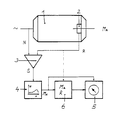
- the single figure shows the block diagram of a device for measuring the output torque in an asynchronous motor 1.
- a roller bearing 2 which in a known manner has an electrical output that delivers a pulse sequence proportional to the rotor speed R.
- Another measured value N is formed by a pulse sequence corresponding to the stator frequency of the asynchronous motor 1 or the mains supply frequency.
- a differential pulse sequence is formed from the two measured values R, H, which is proportional to the slip speed S of the asynchronous motor 1.
- the slip speed S increases with the output torque M A , but is not strictly proportional to it and is dependent on other engine specifications and design features.
- a computing module 4 with a read-only memory in which the characteristic curve "output torque M A / slip speed S" corresponding to the respective motor type is stored.
- the output signal thus forms the correct value for the output torque M A for each slip speed S. It is displayed in a commercially available display 5 or can also be processed in some other way, if necessary using limit values for monitoring.
- Another use results in connection with a counter 6, which adds up the total of an effective output torque M A - approximately by the sum of all revolutions of the rotor - and offsets it with the respective value of the output torque M A.
- the used value of the service life of a statistical service life basis can be deducted in order to indicate the remaining service life, for example of bearings and other engine parts.
Landscapes
- Physics & Mathematics (AREA)
- General Physics & Mathematics (AREA)
- Engineering & Computer Science (AREA)
- Power Engineering (AREA)
- Force Measurement Appropriate To Specific Purposes (AREA)
- Combined Controls Of Internal Combustion Engines (AREA)
- Testing Of Engines (AREA)
Description
- Messen der Umlaufdrehzahl des Ständerfeldes
- Messen der Rotordrehzahl
- Bildung eines Meßwertes für die Schlupfdrehzahl aus der Differenz von Rotordrehzahl und Umlaufdrehzahl
- Bildung eines Meßwertes für das Abtriebsmoment aus der Schlupfdrehzahl und statistischen motoreigenen Kennwerten für das Abtriebsmoment,
- ein Adapter zur Messung der Umlaufdrehzahl des Ständerfeldes
- ein Sensor zur Messung der Rotordrehzahl
- eine Differenzschaltung zur Bildung der Schlupfdrehzahl
- ein Festwertspeicher für die motoreigene Charakteristik von Antriebsmoment in Abhängigkeit zur Schlupfdrehzahl mit einem Eingang tur die Schlupfdrehzahl und einem Ausgang für das Abtriebsmoment und
- eine Anzeigevorrichtung für das Abtriebsmoment mit Ausgängen zur Weiterverarbeitung des Meßsignals.
Claims (3)
- Verfahren zur Messung des Abtriebsmomentes eines Asynchron-Motors durchMessen der Umlaufdrehzahl N des Ständerfeldes ;Messen der Rotordrehzahl R ;Bildung eines Meßwertes für die Schlupfdrehzahl S aus der Differenz von Rotordrehzahl R und Umlaufdrehzahl N gekennzeichnet durchBildung eines Meßwertes für das Abtriebsmomen MA aus der Schlupfdrehzahl S und statistischen, motoreigenen Kennwerten für das Abtriebsmoment MA undBildung eines Meßwertes für die Beanspruchung aus Rotordrehzahl R und Abtriebsmoment MA.
- Vorrichtung zur Messung des Abtriebsmomentes eines Asynchron-Motors nach dem in Anspruch 1 gekennzeichneten Verfahren, umfassendeinen Adapter zur Messung der Umlaufdrehzahl N des Ständerfeldeseinen Sensor (2) zur Messung der Rotordrehzahl Reine Differenzschaltung (3) zur Bildung der Schlupfdrehzahl S, gekennzeichnet durcheinen Festwertspeicher (4) für die motoreigene Charakteristik von Abtriebsmoment MA in Abhängigkeit zur Schlupfdrehzahl S mit einem Eingang für die Schlupfdrehzahl S und einem Ausgang für das Abtriebsmoment MAeine Anzeigevorrichtung (5) für das Abtriebsmoment M mit Ausgängen zur Weiterverarbeitung des Meßsignals undeinen Schaltungsbaustein (6) zur Bildung eines Meßwertes aus Abtriebsmoment MA und Abtriebsdrehzahl R für die Beanspruchung der durch den Asynchron-Motor (1) angetriebenen Einheit.
- Vorrichtung nach Anspruch 2, gekennzeichnet durch die Ausführung eines der Motorlager (2) als Sensorlager zur Messung der Rotordrehzahl R.
Applications Claiming Priority (2)
| Application Number | Priority Date | Filing Date | Title |
|---|---|---|---|
| DE19621046 | 1996-05-24 | ||
| DE19621046A DE19621046A1 (de) | 1996-05-24 | 1996-05-24 | Verfahren und Vorrichtung zur Messung des Abtriebsmomentes |
Publications (3)
| Publication Number | Publication Date |
|---|---|
| EP0809095A2 EP0809095A2 (de) | 1997-11-26 |
| EP0809095A3 EP0809095A3 (de) | 1997-12-17 |
| EP0809095B1 true EP0809095B1 (de) | 1999-11-17 |
Family
ID=7795281
Family Applications (1)
| Application Number | Title | Priority Date | Filing Date |
|---|---|---|---|
| EP97107861A Expired - Lifetime EP0809095B1 (de) | 1996-05-24 | 1997-05-14 | Verfahren und Vorrichtung zur Messung des Abtriebsmomentes eines Elektromotors |
Country Status (4)
| Country | Link |
|---|---|
| US (1) | US6072294A (de) |
| EP (1) | EP0809095B1 (de) |
| JP (1) | JPH1062274A (de) |
| DE (2) | DE19621046A1 (de) |
Families Citing this family (5)
| Publication number | Priority date | Publication date | Assignee | Title |
|---|---|---|---|---|
| US6144834A (en) * | 1999-09-28 | 2000-11-07 | Xerox Corporation | Self biasing, extended nip electrostatic cleaner |
| DE102007038890B4 (de) * | 2007-08-17 | 2016-09-15 | Robert Bosch Gmbh | Verfahren und Vorrichtung zur Bestimmung der Lebensdauer von im Arbeitsbetrieb befindlichen Bauteilen |
| FI121721B (fi) * | 2008-09-04 | 2011-03-15 | Abb Oy | Menetelmä ja järjestely moottorin pyörimisnopeuden määrittämiseen |
| KR102052562B1 (ko) * | 2012-11-08 | 2019-12-05 | 엘지이노텍 주식회사 | 토크 측정장치 |
| CN106441664B (zh) * | 2016-11-21 | 2019-04-19 | 南通大学 | 一种开关磁阻电机转矩测量仪 |
Family Cites Families (17)
| Publication number | Priority date | Publication date | Assignee | Title |
|---|---|---|---|---|
| US32579A (en) * | 1861-06-18 | Ventilating millstowes | ||
| AT289964B (de) * | 1968-04-18 | 1971-05-10 | Siemens Ag | Elektrische Einrichtung zur Istwertbildung in einer vermaschten Regelanordnung für eine insbesondere umrichtergespeiste Drehstromasynchronmaschine |
| DE1900347A1 (de) * | 1969-01-04 | 1970-07-30 | Philips Patentverwaltung | Anordnung zur frequenzanalogen Drehlzahlregelung einer wechselrichtergespeisten Induktionsmaschine |
| US3887855A (en) * | 1973-11-28 | 1975-06-03 | Cleveland Machine Controls | Motor speed modifier control |
| JPS5833781B2 (ja) * | 1976-12-10 | 1983-07-22 | 三菱電機株式会社 | タ−ビン発電機の軸監視装置 |
| JPS5587018A (en) * | 1978-12-25 | 1980-07-01 | Shin Nippon Koki Kk | Arithmetic unit for motor torque of induction motor |
| JPS583591A (ja) * | 1981-06-25 | 1983-01-10 | Toyo Electric Mfg Co Ltd | 誘導電動機制御方法 |
| US4491775A (en) * | 1981-10-26 | 1985-01-01 | Colin Frank Norton | Motor operating parameter sensing apparatus |
| JPS61117579U (de) * | 1985-01-08 | 1986-07-24 | ||
| DE3513510A1 (de) * | 1985-04-16 | 1986-10-23 | Hans Heynau GmbH, 8000 München | Verfahren und anordnung zur steuerung eines asynchronmotors |
| US4659976A (en) * | 1985-04-24 | 1987-04-21 | Dresser Industries, Inc. | Method and apparatus for maximizing utilization of an electric motor under load |
| EP0228535A1 (de) * | 1985-12-04 | 1987-07-15 | Siemens Aktiengesellschaft | Verfahren und Vorrichtung zur Bestimmung des Flusswinkels einer Drehfeldmaschine bzw. zum Lageorientierten Betrieb der Maschine |
| JP2577387B2 (ja) * | 1987-07-08 | 1997-01-29 | 株式会社東芝 | 逐次比較型ad変換器 |
| EP0395783A1 (de) * | 1989-05-05 | 1990-11-07 | Gmn Georg Müller Nürnberg Ag | Sensorlager zur Erfassung von Drehzahl und/oder Verdrehwinkel |
| US5509879A (en) * | 1994-07-22 | 1996-04-23 | Lanzagorta; Ignacio | Portable exerciser with a constant resistance |
| JP2848253B2 (ja) * | 1994-09-12 | 1999-01-20 | 日本電気株式会社 | 駆動部寿命予測装置 |
| DE29503416U1 (de) * | 1995-03-02 | 1995-07-20 | Höhn, Carsten, Dipl.-Ing, 28832 Achim | Gerät zur Ermittlung der dynamischen Beanspruchung an Bauteilen, Anlagen und Maschinen |
-
1996
- 1996-05-24 DE DE19621046A patent/DE19621046A1/de not_active Withdrawn
-
1997
- 1997-05-06 US US08/851,624 patent/US6072294A/en not_active Expired - Fee Related
- 1997-05-14 DE DE59700714T patent/DE59700714D1/de not_active Expired - Fee Related
- 1997-05-14 EP EP97107861A patent/EP0809095B1/de not_active Expired - Lifetime
- 1997-05-21 JP JP9146075A patent/JPH1062274A/ja active Pending
Also Published As
| Publication number | Publication date |
|---|---|
| DE59700714D1 (de) | 1999-12-23 |
| US6072294A (en) | 2000-06-06 |
| EP0809095A3 (de) | 1997-12-17 |
| JPH1062274A (ja) | 1998-03-06 |
| DE19621046A1 (de) | 1997-11-27 |
| EP0809095A2 (de) | 1997-11-26 |
Similar Documents
| Publication | Publication Date | Title |
|---|---|---|
| CN100504337C (zh) | 检测离心泵故障的方法和装置 | |
| DE102014111400B4 (de) | Vorrichtung zur Bestimmung einer Lagerlebensdauer | |
| EP3824302B1 (de) | Verfahren zum bewerten eines schwingungsverhaltens eines elektromotors | |
| DE19728381B4 (de) | Verfahren und Schaltung zur Funktionsüberwachung einer Sensorbrücke | |
| EP2880404B1 (de) | Verfahren zum erkennen eines fehlerfalls einer motoranordnung mit einer elektrischen maschine und motorsteuergerät | |
| DE19961528C1 (de) | Verfahren zur Überwachung des radialen Spalts zwischen dem Rotor und dem Stator eines elektrischen Generators und Vorrichtung zur Durchführung des Verfahrens | |
| DE102011053608B4 (de) | Drehwinkelerfassungsvorrichtung und elektrisches Servolenkungssystem, das dieselbe verwendet | |
| DE102015213084B4 (de) | Verfahren zur Überwachung eines Lagersystems | |
| US6498992B1 (en) | Defect diagnosis method and defect diagnosis apparatus | |
| DE102009025481A1 (de) | Verfahren und Vorrichtung zur quantitativen Ermittlung des Unwuchtzustandes sowie Verfahren zur Ermittlung des Einspannzustandes von Werkstücken | |
| EP0809095B1 (de) | Verfahren und Vorrichtung zur Messung des Abtriebsmomentes eines Elektromotors | |
| EP2244080A1 (de) | Verfahren zur Zustandsüberwachung bei Lagern permanenterregter Synchronmaschinen sowie zugehörige Einrichtung zur Zustandsüberwachung | |
| EP3109999B1 (de) | Verfahren und vorrichtung zur ermittlung einer physikalischen grösse einer mehrphasen-synchronmaschine | |
| DE3881564T2 (de) | Achsentorsionsvibrations-Überwachungsgerät für eine Anordnung mit mehreren Massen an einer rotierenden Achse. | |
| EP3036408B1 (de) | Verfahren zum betreiben einer strömungsmaschine mit überlastschutz und strömungsmaschine mit einer vorrichtung zur durchführung des verfahrens | |
| EP2275888A2 (de) | Rotorlagegeber mit einer Kompensationseinheit zur Fehlerkompensation für einen drehzahlgeregelten Servomotor | |
| DE102004050898B4 (de) | Verfahren und Einrichtung zur Überwachung einer Temperatur eines Lagers einer rotierend umlaufenden Welle | |
| WO2020234256A1 (de) | Verfahren zum ermitteln eines fehlers einer elektrischen maschine und elektrische maschine | |
| EP3861410B1 (de) | Verfahren und system zur überwachung des betriebes mindestens einer antriebskomponente | |
| DE102015120263B4 (de) | Verfahren zur Verschleißbestimmung, Messgerät, Steuervorrichtung dazu sowie Antriebsvorrichtung umfassend die Steuervorrichtung | |
| DE102017006370B4 (de) | Drehmomentmessverfahren für einen Doppelflansch-Drehmomentaufnehmer | |
| DE112004002642B4 (de) | Plausibilitätsprüfung eines elektrischen Drei-Phasen-Systems | |
| DE102005045284A1 (de) | Drehzahlüberwachungsvorrichtung | |
| EP3014756A1 (de) | Verfahren zur erkennung einer winkelfehlstellung eines elektrischen motors | |
| DE102005004835B4 (de) | Verfahren zur Überwachung der Temperatur zumindest eines Lagers einer elektrischen Maschine, hiermit korrespondierende Überwachungseinrichtung sowie elektrische Maschine mit einer derartigen Überwachungseinrichtung |
Legal Events
| Date | Code | Title | Description |
|---|---|---|---|
| PUAI | Public reference made under article 153(3) epc to a published international application that has entered the european phase |
Free format text: ORIGINAL CODE: 0009012 |
|
| PUAL | Search report despatched |
Free format text: ORIGINAL CODE: 0009013 |
|
| AK | Designated contracting states |
Kind code of ref document: A2 Designated state(s): DE FR GB IT SE |
|
| AK | Designated contracting states |
Kind code of ref document: A3 Designated state(s): DE FR GB IT SE |
|
| 17P | Request for examination filed |
Effective date: 19980804 |
|
| 17Q | First examination report despatched |
Effective date: 19981204 |
|
| GRAG | Despatch of communication of intention to grant |
Free format text: ORIGINAL CODE: EPIDOS AGRA |
|
| GRAG | Despatch of communication of intention to grant |
Free format text: ORIGINAL CODE: EPIDOS AGRA |
|
| GRAH | Despatch of communication of intention to grant a patent |
Free format text: ORIGINAL CODE: EPIDOS IGRA |
|
| GRAH | Despatch of communication of intention to grant a patent |
Free format text: ORIGINAL CODE: EPIDOS IGRA |
|
| GRAA | (expected) grant |
Free format text: ORIGINAL CODE: 0009210 |
|
| AK | Designated contracting states |
Kind code of ref document: B1 Designated state(s): DE FR GB IT SE |
|
| GBT | Gb: translation of ep patent filed (gb section 77(6)(a)/1977) |
Effective date: 19991117 |
|
| REF | Corresponds to: |
Ref document number: 59700714 Country of ref document: DE Date of ref document: 19991223 |
|
| ITF | It: translation for a ep patent filed | ||
| ET | Fr: translation filed | ||
| PLBE | No opposition filed within time limit |
Free format text: ORIGINAL CODE: 0009261 |
|
| STAA | Information on the status of an ep patent application or granted ep patent |
Free format text: STATUS: NO OPPOSITION FILED WITHIN TIME LIMIT |
|
| 26N | No opposition filed | ||
| REG | Reference to a national code |
Ref country code: GB Ref legal event code: IF02 |
|
| PGFP | Annual fee paid to national office [announced via postgrant information from national office to epo] |
Ref country code: SE Payment date: 20090528 Year of fee payment: 13 Ref country code: IT Payment date: 20090527 Year of fee payment: 13 Ref country code: FR Payment date: 20090518 Year of fee payment: 13 Ref country code: DE Payment date: 20090528 Year of fee payment: 13 |
|
| PGFP | Annual fee paid to national office [announced via postgrant information from national office to epo] |
Ref country code: GB Payment date: 20090528 Year of fee payment: 13 |
|
| GBPC | Gb: european patent ceased through non-payment of renewal fee |
Effective date: 20100514 |
|
| EUG | Se: european patent has lapsed | ||
| REG | Reference to a national code |
Ref country code: FR Ref legal event code: ST Effective date: 20110131 |
|
| PG25 | Lapsed in a contracting state [announced via postgrant information from national office to epo] |
Ref country code: IT Free format text: LAPSE BECAUSE OF NON-PAYMENT OF DUE FEES Effective date: 20100514 Ref country code: SE Free format text: LAPSE BECAUSE OF NON-PAYMENT OF DUE FEES Effective date: 20100515 |
|
| PG25 | Lapsed in a contracting state [announced via postgrant information from national office to epo] |
Ref country code: DE Free format text: LAPSE BECAUSE OF NON-PAYMENT OF DUE FEES Effective date: 20101201 |
|
| PG25 | Lapsed in a contracting state [announced via postgrant information from national office to epo] |
Ref country code: FR Free format text: LAPSE BECAUSE OF NON-PAYMENT OF DUE FEES Effective date: 20100531 |
|
| PG25 | Lapsed in a contracting state [announced via postgrant information from national office to epo] |
Ref country code: GB Free format text: LAPSE BECAUSE OF NON-PAYMENT OF DUE FEES Effective date: 20100514 |