EP0809043B1 - Kraftfahrzeuggetriebe mit hydraulischem Servo - Google Patents
Kraftfahrzeuggetriebe mit hydraulischem Servo Download PDFInfo
- Publication number
- EP0809043B1 EP0809043B1 EP96120372A EP96120372A EP0809043B1 EP 0809043 B1 EP0809043 B1 EP 0809043B1 EP 96120372 A EP96120372 A EP 96120372A EP 96120372 A EP96120372 A EP 96120372A EP 0809043 B1 EP0809043 B1 EP 0809043B1
- Authority
- EP
- European Patent Office
- Prior art keywords
- clutch
- hydraulic servo
- piston
- push
- reaction member
- Prior art date
- Legal status (The legal status is an assumption and is not a legal conclusion. Google has not performed a legal analysis and makes no representation as to the accuracy of the status listed.)
- Expired - Lifetime
Links
- 230000005540 biological transmission Effects 0.000 title claims description 31
- 238000010276 construction Methods 0.000 description 5
- 238000010586 diagram Methods 0.000 description 2
- 239000000969 carrier Substances 0.000 description 1
- 230000001419 dependent effect Effects 0.000 description 1
- 238000005516 engineering process Methods 0.000 description 1
- 238000004519 manufacturing process Methods 0.000 description 1
- 238000000034 method Methods 0.000 description 1
Images


Classifications
-
- F—MECHANICAL ENGINEERING; LIGHTING; HEATING; WEAPONS; BLASTING
- F16—ENGINEERING ELEMENTS AND UNITS; GENERAL MEASURES FOR PRODUCING AND MAINTAINING EFFECTIVE FUNCTIONING OF MACHINES OR INSTALLATIONS; THERMAL INSULATION IN GENERAL
- F16H—GEARING
- F16H63/00—Control outputs from the control unit to change-speed- or reversing-gearings for conveying rotary motion or to other devices than the final output mechanism
- F16H63/02—Final output mechanisms therefor; Actuating means for the final output mechanisms
- F16H63/30—Constructional features of the final output mechanisms
- F16H63/3023—Constructional features of the final output mechanisms the final output mechanisms comprising elements moved by fluid pressure
- F16H63/3026—Constructional features of the final output mechanisms the final output mechanisms comprising elements moved by fluid pressure comprising friction clutches or brakes
-
- F—MECHANICAL ENGINEERING; LIGHTING; HEATING; WEAPONS; BLASTING
- F16—ENGINEERING ELEMENTS AND UNITS; GENERAL MEASURES FOR PRODUCING AND MAINTAINING EFFECTIVE FUNCTIONING OF MACHINES OR INSTALLATIONS; THERMAL INSULATION IN GENERAL
- F16D—COUPLINGS FOR TRANSMITTING ROTATION; CLUTCHES; BRAKES
- F16D25/00—Fluid-actuated clutches
- F16D25/08—Fluid-actuated clutches with fluid-actuated member not rotating with a clutching member
- F16D25/082—Fluid-actuated clutches with fluid-actuated member not rotating with a clutching member the line of action of the fluid-actuated members co-inciding with the axis of rotation
-
- F—MECHANICAL ENGINEERING; LIGHTING; HEATING; WEAPONS; BLASTING
- F16—ENGINEERING ELEMENTS AND UNITS; GENERAL MEASURES FOR PRODUCING AND MAINTAINING EFFECTIVE FUNCTIONING OF MACHINES OR INSTALLATIONS; THERMAL INSULATION IN GENERAL
- F16H—GEARING
- F16H57/00—General details of gearing
- F16H57/08—General details of gearing of gearings with members having orbital motion
Definitions
- the invention relates to a vehicular power transmission.
- a hydraulic servo for applying a clutch to connect rotary elements to each other is generally mounted in one of the rotary elements.
- the technology of the so-called "stationary cylinder type construction", in which the hydraulic servo is arranged in the case of the power transmission system, is disclosed in the prior art in Japanese Patent Laid-Open No. 119761/1995.
- the stationary cylinder type construction is adopted, the push force of the hydraulic servo cannot be received, unlike the prior art hydraulic servo mounted in the rotary element, by a reaction member on the rotary element having the servo to constitute a closed loop of force in the rotary element thereby to establish an unbalance force.
- this technique therefore, there is adopted the construction in which the push force of the hydraulic servo is transmitted through the reaction member to the case.
- a helical gear having a tooth trace inclined with respect to the axis is used to smoothen the power transmission through the meshing portion of the gear.
- the helical gear establishes a thrust force at the time of transferring the power, but the acting direction of the thrust force changes with the running state of the vehicle.
- the thrust force is inverted between the state in which the vehicle is driven by the power of the engine (to be called the driving time), i.e., when the throttle is ON, and the state in which the engine is driven by the wheels (to be called the coasting time) by the coasting of the vehicle, i.e., when the throttle is OFF.
- a predetermined gap is formed, between the individual members of the power transmission system, to allow for manufacturing error, thermal expansion or other similar factors.
- the reaction member moves by the gap so as to reduce the clearance in the application direction of the clutch thereby to reduce the ineffective stroke of the piston.
- the thrust force acts in the same direction as that of the push force of the hydraulic servo, on the other hand, the clearance of the clutch is not reduced so that the ineffective stroke is elongated.
- the oil pressure is supplied to the hydraulic servo so as to apply the clutch at the driving time and at the coasting time, the ineffective stroke time changes to lower the controllability.
- EP-A-0 733 827 discloses a transmission comprising a hydraulic servo unit, a helical gear, a clutch for connecting predetermined rotary elements to each other; and a hydraulic servo for applying the clutch.
- the hydraulic servo includes a cylinder; a piston fitted in the cylinder; a push member abutting against the piston through a bearing for transmitting the push force of the piston to the clutch; and a return spring for the piston.
- One of the rotary elements includes a reaction member opposed to the push member for transmitting the push force of the piston to a case.
- the cylinder is a stationary cylinder formed in the case.
- the return spring is arranged between the push member and the reaction member and loaded to apply a load higher than the thrust force of the helical gear, as acting upon the reaction member.
- An object of the invention is to prevent the hydraulic servo unit from being lowered in the controllability of the clutch while setting the load of the return spring for holding the clearance in the clutch applying direction at a low value.
- the return spring is arranged between the reaction member and the push member so that it acts to retain the clearance of the push member for the clutch. Moreover, the load by the return spring causes a load higher than the thrust force of the helical gear, as acting on the reaction member, to act on the reaction member and the push member. Irrespective of the change in the thrust force acting on the reaction member, therefore, the push member is pushed back at all times so that the clearance between the clutch and the push member of the hydraulic servo is kept constant at all times. As a result, the controllability of the clutch is not deteriorated.
- the thrust force is lower at the coasting time than at the driving time so that the spring load necessary for the return spring can be lowered by causing the thrust force to act against the push force at the coasting time.
- the spring load of the return spring can be lowered to lower the oil pressure necessary for applying the clutch.
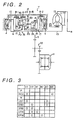
- Fig. 2 shows a power transmission system to which the invention is applied.
- the system is exemplified by a transfer system of transverse construction and is structured to include a torque converter 12 having a lockup clutch 11 connected to the engine of a vehicle; an automatic transmission T having a speed change mechanism M composed of three stages of planetary gear sets M1, M2 and M3 for shifting the output of the torque converter 12 into five forward and one reverse speeds; a counter gear 20 for decelerating the shifted output to transmit the decelerated output to a differential unit 21; and the differential unit 21 for transmitting the transmitted output to the right and left wheels of the vehicle.
- a transfer system of transverse construction is structured to include a torque converter 12 having a lockup clutch 11 connected to the engine of a vehicle; an automatic transmission T having a speed change mechanism M composed of three stages of planetary gear sets M1, M2 and M3 for shifting the output of the torque converter 12 into five forward and one reverse speeds; a counter gear 20 for decelerating the shifted output to transmit the dec
- the pinion gears P1, P2 of larger and smaller diameters of the two gear sets M1, M2, respectively, are connected directly, and the individual ring gears R1, R3 and carriers C3, C1 of the two gear sets M1, M3, respectively, are connected to each other.
- the sun gear S1 and the carrier C1 of the gear set M1 are so connected through clutches (C-1, C-2), respectively, to an input shaft 14 leading to a turbine shaft 13 of the torque converter 12 that they may act as input elements.
- the ring gear R1 and the carrier C3, as connected to each other are connected through an output shaft 15 to an output gear 19 acting as an output element.
- the sun gear S1 of the gear set M1 can be fixed on a transmission case 10 by a brake B-1; the sun gear S2 of the gear set M2 can be fixed on the transmission case 10 by a brake B-2; the sun gear S3 of the gear set M3 can also be fixed on the transmission case 10 by a brake B-3; and the ring gear R3, as connected to the carrier C1, can be fixed on the transmission case 10 by a brake B-R.
- the sun gear S1 is connected to the clutch C-1 through a sun gear shaft 16 fitted on the outer circumference of the input shaft 14; the carrier C1 is connected to the clutch C-2 through a carrier shaft 17 fitted on the outer circumference of the input shaft 14; and the sun gear S3 is connected to a brake B-3 through a sun gear shaft 18 fitted on the outer circumference of the carrier shaft 17.
- the individual brakes B-1, B-2, B-3, other than the brake B-R have a band brake structure, and the brake B-R is a multiple disc brake structure, although the brakes are not limited thereto.
- the output gear 19 is connected to the differential unit 21 through the counter gear 20 acting as a reduction gear.
- the automatic transmission T thus structured establishes the individual gear stages by feeding the oil pressure to hydraulic servos corresponding to the individual clutches and brakes, under the control of a hydraulic control unit (not-shown), to apply (as indicated by symbol O) and release (as indicated by blanks) the individual clutches and brakes, as shown in Fig. 3.
- the first speed (1 ST ) range is established when the clutch C-1 and the brake B-3 are applied.
- the rotation of the input shaft 14 enters the sun gear S1 through the clutch C-1 so that the rotation of the carrier C3 decelerated the most by the fixture of the sun gear S3, as effected by the application of the brake B-3, is output to the output gear 19.
- the second speed (2 ND ) range is established by the applications of the clutch C-2 and the brake B-3.
- the input as having entered the carrier shaft 17 through the clutch C-2, enters, as it is, the ring gear R3 through the carrier C1 so that the differential rotation of the carrier C3, as employing the sun gear S3 fixed by the application of the brake B-3 as a reaction element, is output to the output gear 19.
- the third speed (3 RD ) range is established by the direct connection of the first planetary gear set M1, as effected by the applications of the two clutches C-1, C-2. At this time, the rotation of the input shaft 14 is output, as it is as the rotation of the carrier C3, to the output gear 19.
- the fourth speed (4 TH ) range designated as the start of overdrive, is established by the application of the clutch C-2 and by the application of the brake B-1 for fixing the sun gear S1. At this time, the rotation of the input shaft 14 is transmitted, as the rotation of the ring gear R1 accelerated by the revolution of the pinion gear P1 from the rotation of the carrier C1, from the carrier C3 to the output gear 19.
- the fifth speed (5 TH ) range is established by the applications of the clutch C-2 and the brake B-2.
- the reverse (REV) range is established by the applications of the clutch C-1 and the brake B-R. At this time, the rotation of the ring gear R1, as reversed and decelerated from the input of the sun gear S1 by the fixture of the carrier C1, is output from the output gear 19 through the carrier C3.
- the invention is embodied by exemplifying a helical gear by the planetary gear set M3, i.e., its ring gear R3, a predetermined rotary element by the input shaft 14 and the sun gear shaft 16 connected to the sun gear S1, a clutch by the clutch C-1, and a hydraulic servo by a hydraulic servo 3.
- the hydraulic servo 3 comprises a cylinder 30; a piston 31 fitted in the cylinder 30; a push member 33 abutting against the piston 31 through a bearing 32 for transmitting the push force of the piston 31 to the clutch C-1; and a return spring 58 of the piston 31.
- the input shaft 14 is equipped with a reaction member 56 opposed to the push member 33 for transmitting the push force of the piston 31 to the case 10, and the cylinder 30 is exemplified by a stationary cylinder formed in the case 10.
- the return spring 58 is arranged between the push member 33 and the reaction member 56 and is set with a load for applying a load, higher than the thrust force acting upon the reaction member 56, to the push member 33 and the reaction member 56.
- the helical tooth of the helical gear R3 is twisted in such a direction that the thrust force to act upon the reaction member 56 is, at a coasting time, in an opposite direction to the load of the return spring 58 and, at a driving time, in the same direction as the load of the return spring 58.
- Reference numeral 4 in Fig. 1 designates a hydraulic servo having a structure similar to that of the hydraulic servo 3.
- the hydraulic servo 4 is likewise composed of a cylinder 40, a piston 41, a bearing 42 and a push member 43.
- numerals 59 to 64 designate individual thrust bearings.
- Fig. 4 is a detailed section showing the hydraulic servo unit and its associated portion.
- the clutch C-1 comprises a hub 53 fixed on the reaction member 56 splined in the input shaft 14; a drum 54 fixed on the end flange of the sun gear shaft 16 and is equipped on its outer circumference with the band drum of the brake B-1; and a frictional plate portion 50 having a plurality of separator plates 51 splined at their inner circumferences in the outer circumference of the hub 53, and a plurality of friction members 52 splined at their outer circumference in the inner circumference of the drum 54, arranged axially alternately of the separator plates 51 and having facings on their two surfaces.
- the hydraulic servo 3 comprises, as has been described hereinbefore, the cylinder 30 or the annular recess which is formed in the case 10, i.e., a cover 10a fastened on the case 10 by bolts; an annular disc-shaped piston 31 fitted slidably in the cylinder 30; the thrust bearing 32 arranged to abut against the end face of the piston 31 closer to the inner circumference; the annular disc-shaped push member 33 arranged between the clutch C-1 and the bearing 32 and confronting the bearing 32 at its inner circumferential side and the frictional plate portion 50 of the clutch C-1 at its outer circumferential portion; and the return spring 58 abutting against the end face of the push member 33 closer to the inner circumference at its one end through the spring seat and against the reaction member 56 at its other end and having a predetermined spring load.
- the push member 33 is provided at its one radially outer side with an abutment portion for the frictional members 52.
- the inner circumference of the abutment portion is splined like the separator plate 51 in the hub 53 connected to the input shaft 14, through the reaction member 56, and can not rotate relatively but can slide axially, and the outer circumference of the abutment portion is so axially extended as to cover the radially outer side of the drum 54 of the clutch C-1, to provide a rotor portion having a detecting slit for a clutch rotation sensor.
- the end portion of the input shaft 14 is supported in a support hole, or recess, in the cover 10a by a radial bearing.
- the reaction member 56 and the input shaft 14 are splined axially slidably.
- the flange 14a, as fitted on the step portion of the input shaft 14, abuts against the cover 10a through the thrust bearing 59.
- the remaining associated portions will not be described as they are designated by the reference numerals of the corresponding portions of Figs. 1 and 2.
- the piston 31 is moved in the direction to apply the clutch C-1, when the oil pressure is fed from a supply oil passage 30c in the cover 10a to an oil chamber 3C of the hydraulic servo 3. Then, the bearing 32 and the push member 33 are accordingly moved to push the frictional plate portion 50 between the reaction member 56 for taking the reaction on the case 10 and the push member 33 thereby to apply the clutch C-1. Since the bearing 32 and the push member 33 are interposed between the piston 31 and the clutch C-1, the push force from the piston 31 can then be transmitted to the frictional plate portion 50 while allowing a relative rotation between the clutch C-1 and the piston 31.
- the clutch C-1 is applied while the vehicle is being driven, at the upshift from the second speed (2 ND ) range to the third speed (3 RD ) range, at the downshift from the fourth speed (4 TH ) range to the third speed (3 RD ) range, and at the downshift from the second speed (2 ND ) range to the first speed (1 ST ) range.
- the carrier C1 is connected to the input shaft 14 by the application of the clutch C-2 so that the ring gear R3 participates as an input element in the power transmission.
- the thrust force of the ring gear R3, acting in the opposite direction to that indicated by a blank arrow of Fig. 1, is transmitted through the carrier C1 and the bearing 62 to the sun gear S3 until it balances with the opposite thrust force being generated in the sun gear S3.
- the reaction member 56 is pushed rightward of the drawing by the set load of the return spring 58, and this thrust force is transmitted through the bearing 60, the sun gear shaft 16, the bearing 61, the flange of the carrier C1, the bearing 62, the sun gear S3, the bearing 63, the flange of the carrier C3 and the bearing 64 to the case 10 so that they are placed in predetermined axially close positions.
- the push member 33 is pushed leftward by its reaction to push back the piston 31 to a predetermined position through the bearing 32 thereby to hold the piston 31 in the position.
- the clearance between the hydraulic servo 3 and the clutch C-1 is held at the predetermined value.
- the thrust force of the ring gear R3 acts in the direction indicated by the blank arrow in Fig. 1, and is transmitted from the flange of the carrier C1 through the bearing 61 to the sun gear shaft 16 and further through the bearing 60 to the reaction member 56.
- This force acts to displace the reaction member 56 leftward of the drawing.
- a load exceeding the thrust force acts upon the reaction member 56 so that the reaction member 56 is placed in the predetermined axially close position by the transmission of a force similar to that of the driving time.
- the push member 33 also pushes back the piston 31 to the predetermined position.
- the clearance between the hydraulic servo 3 and the clutch C-1 is held at a value similar to that of the driving time.
- the return spring 58 is arranged between the reaction member 56 and the push member 33 so that it acts to retain the clearance of the push member 33 from the clutch C-1.
- the load of the return spring 58 is higher than the thrust force of the helical gear R3 acting upon the reaction member 56 to act upon the reaction member 56 and the push member 33. Irrespective of the change in the thrust force acting upon the reaction member 56, therefore, the push member 33 is pushed back to a close state, through the individual intermediate members, from the case 10 so that the clearance between the clutch C-1 and the push member 33 of the hydraulic servo 3 is held constant at all times.
- the piston stroke to the engagement as effected by supplying the oil pressure, is stabilized to prevent the reduction in the controllability of the clutch C-1.
- the thrust force is relatively low at the coasting time (usually some tenths of that at the driving time).
- the spring load necessary for the return spring 58 can be set to a lower value than by causing the thrust force at the driving time to oppose the push force.
- the oil pressure necessary for applying the clutch C-1 can be lowered.
Landscapes
- Engineering & Computer Science (AREA)
- General Engineering & Computer Science (AREA)
- Mechanical Engineering (AREA)
- Physics & Mathematics (AREA)
- Fluid Mechanics (AREA)
- Hydraulic Clutches, Magnetic Clutches, Fluid Clutches, And Fluid Joints (AREA)
- Gear-Shifting Mechanisms (AREA)
Claims (2)
- Getriebe mit einer hydraulischen Servoeinheit, mit einer Zahnradanordnung (R3) mit Schrägverzahnung, mit einer Kupplung (C-1) zum Verbinden vorbestimmter Drehelemente miteinander, und einem hydraulischen Servomechanismus (3) zum Einrücken der Kupplung, wobei der hydraulische Servomechanismus umfaßt: einen Zylinder (30); einen in den Zylinder (30) eingesetzten Kolben (31); ein über ein Lager (32) an dem Kolben (31) anliegendes Stoßelement (33) zum Übertragen der Stoßkraft des Kolbens (31) auf die Kupplung (C-1); und eine Rückholfeder (58) für den Kolben (31), wobei eines der Drehelemente ein dem Stoßelement (33) gegenüberliegendes Reaktionselement (56) zum Übertragen der Stoßkraft des Kolbens (31) auf ein Gehäuse (10) enthält, der Zylinder (30) ein in dem Gehäuse (10) gebildeter stationärer Zylinder ist und die Rückholfeder (58) zwischen dem Stoßelement (33) und dem Reaktionselement (56) angeordnet und so belastet ist, daß sie eine Belastung ausübt, die höher als die Schubkraft der Zahnradanordnung (R3) mit Schrägverzahnung ist, bei Einwirkung auf das Reaktionselement (56), und wobei die auf das Reaktionselement (56) einwirkende Schubkraft in einer antriebslosen Phase in der zur Belastung durch die Rückholfeder (58) entgegengesetzten Richtung und in einer Antriebsphase in der gleichen Richtung wie diejenige der Belastung durch die Rückholfeder (58) gerichtet ist.
- Getriebe nach Anspruch 1, bei dem die Schrägverzahnung des Schrägradgetriebes (R3) in einer solchen Richtung gewunden ist, daß die Schubkraft auf das Reaktionselement (56) einwirkt.
Applications Claiming Priority (3)
| Application Number | Priority Date | Filing Date | Title |
|---|---|---|---|
| JP14852396A JP3814870B2 (ja) | 1996-05-21 | 1996-05-21 | 車両用動力伝達装置の油圧サーボ装置 |
| JP14852396 | 1996-05-21 | ||
| JP148523/96 | 1996-05-21 |
Publications (3)
| Publication Number | Publication Date |
|---|---|
| EP0809043A2 EP0809043A2 (de) | 1997-11-26 |
| EP0809043A3 EP0809043A3 (de) | 1998-06-03 |
| EP0809043B1 true EP0809043B1 (de) | 2002-08-14 |
Family
ID=15454689
Family Applications (1)
| Application Number | Title | Priority Date | Filing Date |
|---|---|---|---|
| EP96120372A Expired - Lifetime EP0809043B1 (de) | 1996-05-21 | 1996-12-18 | Kraftfahrzeuggetriebe mit hydraulischem Servo |
Country Status (4)
| Country | Link |
|---|---|
| US (1) | US5908096A (de) |
| EP (1) | EP0809043B1 (de) |
| JP (1) | JP3814870B2 (de) |
| DE (1) | DE69622994T2 (de) |
Families Citing this family (7)
| Publication number | Priority date | Publication date | Assignee | Title |
|---|---|---|---|---|
| JP3885612B2 (ja) * | 2002-03-04 | 2007-02-21 | 株式会社日立製作所 | 自動車用クラッチ |
| US7070532B2 (en) * | 2003-08-26 | 2006-07-04 | General Motors Corporation | Planetary transmission having a rotating-type torque-transmitting mechanism with a stationary piston |
| WO2005106274A1 (ja) * | 2004-04-30 | 2005-11-10 | Hitachi, Ltd. | 機械式自動変速機のクラッチ構造 |
| DE102010010922C5 (de) * | 2009-08-14 | 2024-08-08 | Borgwarner Inc. | Parallele Doppelkupplungseinrichtung und Antriebsstrang mit einer solchen parallelen Doppelkupplungseinrichtung |
| DE102010021036A1 (de) * | 2010-05-19 | 2011-11-24 | Audi Ag | Doppelkupplung für ein Doppelkupplungs-Wechselgetriebe in Kraftfahrzeugen |
| DE102015218591A1 (de) | 2015-09-28 | 2017-03-30 | Zf Friedrichshafen Ag | Getriebe für ein Kraftfahrzeug, sowie Antriebsstrang für ein Kraftfahrzeug |
| US10590997B2 (en) * | 2017-12-12 | 2020-03-17 | Schaeffler Technologies AG & Co. KG | Piston assembly |
Family Cites Families (8)
| Publication number | Priority date | Publication date | Assignee | Title |
|---|---|---|---|---|
| US3038575A (en) * | 1959-02-09 | 1962-06-12 | Quinten A Hansen | Fluid pressure operated clutch with stationary cylinder assembly |
| US3251247A (en) * | 1962-10-15 | 1966-05-17 | Alan S Lamburn | Drive transmission devices and, in particular, planetary drive transmission devices |
| US3684069A (en) * | 1970-10-22 | 1972-08-15 | Lawrence H Pray | Hydraulic disc clutch |
| DE3636175A1 (de) * | 1986-10-24 | 1988-04-28 | Bayerische Motoren Werke Ag | Sperrbares ausgleichsgetriebe |
| US5234090A (en) * | 1992-09-21 | 1993-08-10 | General Motors Corporation | Clearance adjustment for a multi-plate fluid operated friction clutch |
| JPH07119761A (ja) | 1993-10-21 | 1995-05-09 | Fuji Heavy Ind Ltd | 自動変速機付車両のクラッチ構造 |
| JP3414077B2 (ja) * | 1995-03-24 | 2003-06-09 | アイシン・エィ・ダブリュ株式会社 | 車両用自動変速機 |
| JP3648806B2 (ja) * | 1995-03-24 | 2005-05-18 | アイシン・エィ・ダブリュ株式会社 | 車両用自動変速機 |
-
1996
- 1996-05-21 JP JP14852396A patent/JP3814870B2/ja not_active Expired - Fee Related
- 1996-12-18 EP EP96120372A patent/EP0809043B1/de not_active Expired - Lifetime
- 1996-12-18 DE DE69622994T patent/DE69622994T2/de not_active Expired - Lifetime
- 1996-12-20 US US08/771,140 patent/US5908096A/en not_active Expired - Lifetime
Also Published As
| Publication number | Publication date |
|---|---|
| EP0809043A2 (de) | 1997-11-26 |
| JPH09310759A (ja) | 1997-12-02 |
| EP0809043A3 (de) | 1998-06-03 |
| US5908096A (en) | 1999-06-01 |
| JP3814870B2 (ja) | 2006-08-30 |
| DE69622994D1 (de) | 2002-09-19 |
| DE69622994T2 (de) | 2003-03-27 |
Similar Documents
| Publication | Publication Date | Title |
|---|---|---|
| US5735376A (en) | Automatic transmission for vehicles | |
| KR100566491B1 (ko) | 자동변속기 | |
| EP0762014B1 (de) | Automatisches Getriebe | |
| US5931275A (en) | Stationary cylinder type clutch device | |
| US4978328A (en) | Automatic transaxle assembly for an automotive vehicle driveline | |
| US6835158B2 (en) | Automatic transmission | |
| US4455890A (en) | Overdrive device for automatic transmissions | |
| JPS6053223B2 (ja) | 自動車用駆動装置 | |
| EP0616150B1 (de) | Epizykloidengetriebe mit Getriebegehäuseverlängerung | |
| EP0809043B1 (de) | Kraftfahrzeuggetriebe mit hydraulischem Servo | |
| EP0825359B1 (de) | Fahrzeug-Automatikgetriebe | |
| EP0733827B1 (de) | Automatisches Getriebe für Fahrzeuge | |
| US4836052A (en) | Compact change speed transmission | |
| US5186693A (en) | Automatic transmission | |
| JP2005180699A (ja) | 自動車用多段自動変速機 | |
| US5591099A (en) | Shift mechanism for automatic transmission with lubricating means for one-way clutch | |
| US4864892A (en) | Automatic transmission mechanism | |
| US5234390A (en) | Gear transmission with undulating surface clutch and brake element connections | |
| US5178588A (en) | Parking gear mounting structure for automatic transmission | |
| US6068572A (en) | Method for reacting thrust loading in an automatic transmission | |
| US6066066A (en) | Thrust bearing bulkhead in a transmission of a motor vehicle | |
| JPH10281239A (ja) | 自動変速機 | |
| EP0037059A2 (de) | Automatisches Dreiganggetriebe mit Drehmomentenverteilung in den zwei oberen Gängen | |
| US5735369A (en) | Band brake drum supporting device for automatic transmission | |
| KR19980021317A (ko) | 자동차용 변속기 |
Legal Events
| Date | Code | Title | Description |
|---|---|---|---|
| PUAI | Public reference made under article 153(3) epc to a published international application that has entered the european phase |
Free format text: ORIGINAL CODE: 0009012 |
|
| AK | Designated contracting states |
Kind code of ref document: A2 Designated state(s): DE GB |
|
| PUAL | Search report despatched |
Free format text: ORIGINAL CODE: 0009013 |
|
| AK | Designated contracting states |
Kind code of ref document: A3 Designated state(s): DE GB |
|
| 17P | Request for examination filed |
Effective date: 19981104 |
|
| 17Q | First examination report despatched |
Effective date: 20010219 |
|
| GRAG | Despatch of communication of intention to grant |
Free format text: ORIGINAL CODE: EPIDOS AGRA |
|
| RTI1 | Title (correction) |
Free format text: TRANSMISSION WITH HYDRAULIC SERVO UNIT |
|
| GRAG | Despatch of communication of intention to grant |
Free format text: ORIGINAL CODE: EPIDOS AGRA |
|
| GRAH | Despatch of communication of intention to grant a patent |
Free format text: ORIGINAL CODE: EPIDOS IGRA |
|
| GRAH | Despatch of communication of intention to grant a patent |
Free format text: ORIGINAL CODE: EPIDOS IGRA |
|
| GRAA | (expected) grant |
Free format text: ORIGINAL CODE: 0009210 |
|
| AK | Designated contracting states |
Kind code of ref document: B1 Designated state(s): DE GB |
|
| REG | Reference to a national code |
Ref country code: GB Ref legal event code: FG4D |
|
| REF | Corresponds to: |
Ref document number: 69622994 Country of ref document: DE Date of ref document: 20020919 |
|
| PG25 | Lapsed in a contracting state [announced via postgrant information from national office to epo] |
Ref country code: GB Free format text: LAPSE BECAUSE OF NON-PAYMENT OF DUE FEES Effective date: 20021218 |
|
| PLBE | No opposition filed within time limit |
Free format text: ORIGINAL CODE: 0009261 |
|
| STAA | Information on the status of an ep patent application or granted ep patent |
Free format text: STATUS: NO OPPOSITION FILED WITHIN TIME LIMIT |
|
| 26N | No opposition filed |
Effective date: 20030515 |
|
| GBPC | Gb: european patent ceased through non-payment of renewal fee |
Effective date: 20021218 |
|
| PGFP | Annual fee paid to national office [announced via postgrant information from national office to epo] |
Ref country code: DE Payment date: 20121213 Year of fee payment: 17 |
|
| REG | Reference to a national code |
Ref country code: DE Ref legal event code: R119 Ref document number: 69622994 Country of ref document: DE |
|
| REG | Reference to a national code |
Ref country code: DE Ref legal event code: R119 Ref document number: 69622994 Country of ref document: DE Effective date: 20140701 |
|
| PG25 | Lapsed in a contracting state [announced via postgrant information from national office to epo] |
Ref country code: DE Free format text: LAPSE BECAUSE OF NON-PAYMENT OF DUE FEES Effective date: 20140701 |