EP0808941B1 - Procédé de fabrication d'un appareil de tamisage à ouvertures en forme de fentes et appareil de tamisage produit par ce procédé - Google Patents
Procédé de fabrication d'un appareil de tamisage à ouvertures en forme de fentes et appareil de tamisage produit par ce procédé Download PDFInfo
- Publication number
- EP0808941B1 EP0808941B1 EP97104439A EP97104439A EP0808941B1 EP 0808941 B1 EP0808941 B1 EP 0808941B1 EP 97104439 A EP97104439 A EP 97104439A EP 97104439 A EP97104439 A EP 97104439A EP 0808941 B1 EP0808941 B1 EP 0808941B1
- Authority
- EP
- European Patent Office
- Prior art keywords
- rods
- reinforcing elements
- recesses
- sorting
- bonding agent
- Prior art date
- Legal status (The legal status is an assumption and is not a legal conclusion. Google has not performed a legal analysis and makes no representation as to the accuracy of the status listed.)
- Revoked
Links
Images

Classifications
-
- B—PERFORMING OPERATIONS; TRANSPORTING
- B07—SEPARATING SOLIDS FROM SOLIDS; SORTING
- B07B—SEPARATING SOLIDS FROM SOLIDS BY SIEVING, SCREENING, SIFTING OR BY USING GAS CURRENTS; SEPARATING BY OTHER DRY METHODS APPLICABLE TO BULK MATERIAL, e.g. LOOSE ARTICLES FIT TO BE HANDLED LIKE BULK MATERIAL
- B07B1/00—Sieving, screening, sifting, or sorting solid materials using networks, gratings, grids, or the like
- B07B1/46—Constructional details of screens in general; Cleaning or heating of screens
- B07B1/4609—Constructional details of screens in general; Cleaning or heating of screens constructional details of screening surfaces or meshes
- B07B1/4618—Manufacturing of screening surfaces
-
- B—PERFORMING OPERATIONS; TRANSPORTING
- B07—SEPARATING SOLIDS FROM SOLIDS; SORTING
- B07B—SEPARATING SOLIDS FROM SOLIDS BY SIEVING, SCREENING, SIFTING OR BY USING GAS CURRENTS; SEPARATING BY OTHER DRY METHODS APPLICABLE TO BULK MATERIAL, e.g. LOOSE ARTICLES FIT TO BE HANDLED LIKE BULK MATERIAL
- B07B1/00—Sieving, screening, sifting, or sorting solid materials using networks, gratings, grids, or the like
- B07B1/12—Apparatus having only parallel elements
-
- B—PERFORMING OPERATIONS; TRANSPORTING
- B07—SEPARATING SOLIDS FROM SOLIDS; SORTING
- B07B—SEPARATING SOLIDS FROM SOLIDS BY SIEVING, SCREENING, SIFTING OR BY USING GAS CURRENTS; SEPARATING BY OTHER DRY METHODS APPLICABLE TO BULK MATERIAL, e.g. LOOSE ARTICLES FIT TO BE HANDLED LIKE BULK MATERIAL
- B07B1/00—Sieving, screening, sifting, or sorting solid materials using networks, gratings, grids, or the like
- B07B1/18—Drum screens
-
- B—PERFORMING OPERATIONS; TRANSPORTING
- B07—SEPARATING SOLIDS FROM SOLIDS; SORTING
- B07B—SEPARATING SOLIDS FROM SOLIDS BY SIEVING, SCREENING, SIFTING OR BY USING GAS CURRENTS; SEPARATING BY OTHER DRY METHODS APPLICABLE TO BULK MATERIAL, e.g. LOOSE ARTICLES FIT TO BE HANDLED LIKE BULK MATERIAL
- B07B1/00—Sieving, screening, sifting, or sorting solid materials using networks, gratings, grids, or the like
- B07B1/46—Constructional details of screens in general; Cleaning or heating of screens
- B07B1/4609—Constructional details of screens in general; Cleaning or heating of screens constructional details of screening surfaces or meshes
- B07B1/4681—Meshes of intersecting, non-woven, elements
-
- D—TEXTILES; PAPER
- D21—PAPER-MAKING; PRODUCTION OF CELLULOSE
- D21D—TREATMENT OF THE MATERIALS BEFORE PASSING TO THE PAPER-MAKING MACHINE
- D21D5/00—Purification of the pulp suspension by mechanical means; Apparatus therefor
- D21D5/02—Straining or screening the pulp
- D21D5/16—Cylinders and plates for screens
-
- Y—GENERAL TAGGING OF NEW TECHNOLOGICAL DEVELOPMENTS; GENERAL TAGGING OF CROSS-SECTIONAL TECHNOLOGIES SPANNING OVER SEVERAL SECTIONS OF THE IPC; TECHNICAL SUBJECTS COVERED BY FORMER USPC CROSS-REFERENCE ART COLLECTIONS [XRACs] AND DIGESTS
- Y10—TECHNICAL SUBJECTS COVERED BY FORMER USPC
- Y10S—TECHNICAL SUBJECTS COVERED BY FORMER USPC CROSS-REFERENCE ART COLLECTIONS [XRACs] AND DIGESTS
- Y10S29/00—Metal working
- Y10S29/902—Filter making
-
- Y—GENERAL TAGGING OF NEW TECHNOLOGICAL DEVELOPMENTS; GENERAL TAGGING OF CROSS-SECTIONAL TECHNOLOGIES SPANNING OVER SEVERAL SECTIONS OF THE IPC; TECHNICAL SUBJECTS COVERED BY FORMER USPC CROSS-REFERENCE ART COLLECTIONS [XRACs] AND DIGESTS
- Y10—TECHNICAL SUBJECTS COVERED BY FORMER USPC
- Y10T—TECHNICAL SUBJECTS COVERED BY FORMER US CLASSIFICATION
- Y10T29/00—Metal working
- Y10T29/49—Method of mechanical manufacture
- Y10T29/496—Multiperforated metal article making
- Y10T29/49604—Filter
-
- Y—GENERAL TAGGING OF NEW TECHNOLOGICAL DEVELOPMENTS; GENERAL TAGGING OF CROSS-SECTIONAL TECHNOLOGIES SPANNING OVER SEVERAL SECTIONS OF THE IPC; TECHNICAL SUBJECTS COVERED BY FORMER USPC CROSS-REFERENCE ART COLLECTIONS [XRACs] AND DIGESTS
- Y10—TECHNICAL SUBJECTS COVERED BY FORMER USPC
- Y10T—TECHNICAL SUBJECTS COVERED BY FORMER US CLASSIFICATION
- Y10T29/00—Metal working
- Y10T29/49—Method of mechanical manufacture
- Y10T29/49826—Assembling or joining
- Y10T29/49908—Joining by deforming
- Y10T29/49925—Inward deformation of aperture or hollow body wall
Definitions
- the invention relates to a method according to the preamble of claim 1.
- Sieves or sieve baskets with good strength and high surface quality can a method can be produced, which is described in DE 42 14 061 A1. There a high-temperature soldering process is used to attach the rod-like profiles applied. The results are excellent, but the process is complex and expensive.
- Strainers or strainer baskets are known from published patent application DE 33 27 422 A1, at which the sorting slots by essentially parallel, rod-like profiles with transverse holding ribs are welded, are formed. Even if it's through This manufacturing process has succeeded in firmly securing the rods with the retaining ribs connect, that is with the required precision, if at all, only with considerable effort feasible. To fix fibers when operating the To avoid screening device, all surfaces touching the fabric must be extremely smooth his. This is the only way to prevent fibers from building up there and earlier or cause constipation later. There have already been proposals, such Smoothing or covering weld seams afterwards. But these measures were mostly suitable to make production more expensive.
- the invention has for its object to provide an economically advantageous method create, with the sieve devices can be produced, the optimal strength and Have surface properties.
- the advantages of the invention particularly affect rod sieve devices whose Sorting slots have a width in a size range below 2 mm.
- Sorting slots have a width in a size range below 2 mm.
- For the Fibrous sorting or washing are slit widths of 0.1 - 0.2 mm common.
- Such screens have to be provided with a very large number of rods, in order to obtain a sufficient screen area in the narrow slots. Therefore, with her Manufacturing the preparation for assembly is very complex. It is true Series production possible to use special devices, but these are also complex and expensive.
- This handling includes e.g. the Transport and turning these semi-finished products.
- the binder forms an insoluble bond at the contact surfaces, e.g. when soldering, gluing or welding. At the Pure contact welding then produces the binder as a melt from the components self.
- Gluing is also an inexpensive connection, as it is relatively low Temperatures is feasible. E.g. a technical two-component adhesive used, the clamping forces are retained. This can e.g. the possibly lower strength of the adhesive connection can be compensated. If you use drawn profiles for the rods, for example made of steel or a steel alloy, special cross-sectional shapes are also available economically and precisely.
- a special case is the expansion of the depressions through elastic deformation of the Reinforcing elements before the bars are inserted or inserted.
- the tolerances don't have to be as narrow as the method that works without deformation. It can also elastic deformation can be kept low. Relatively low holding forces are sufficient off, since only the position of the bars is to be secured during handling.
- a particularly important application is the use of straight strip-shaped Reinforcing elements with the wells already described. After in one Kind of mat formation the rods have been inserted can by subsequent Bending, e.g. Round rolling the reinforcement elements the final shape of the Screening device are generated. In the same operation, the Bars and thus their fixation required for the further manufacturing process. A further reduction in the cost of the procedure is possible if the wells in the Reinforcing elements are designed so that the bars are vertical - possibly with Pressure forces - can be inserted, i.e. not pushed from the side have to. The fixation of the rods in the reinforcing elements until the end of the Manufacturing process can, but need not, then by deforming the Reinforcing elements are made.
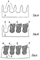
- FIGS. 1 a - 1 c The most important manufacturing steps of the method according to the invention are schematically recorded in FIGS. 1 a - 1 c.
- 1 a shows the part of a reinforcing element 1 with the recesses 4 that have already been introduced.
- a common method for producing such recesses is, for example, laser cutting. To achieve higher precision, electrical erosion can also be useful.
- the reinforcing element contains a large number of such depressions in the manufacture of the usual screening devices.
- Fig. 1 b three rods 2 are already inserted into the recesses, it being apparent that the shape of the recess on the sides of the rod 2 leaves some air in each case. This makes it easy to insert the rod.
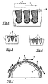
- the section in Fig. 2 shows a perspective view of part of the Reinforcing element 1, in which the rods 2 are inserted and already fastened therein. It can be seen that a slot screen with the columns 3 is formed by this arrangement through which the liquid to be sorted flows in the direction of flow (arrow S) can step through. In operation, parts whose size is the free gap width exceed, withheld and dissipated in a manner known per se.
- a Well 4 for receiving a rod is shown here without the rod. That as Binder 5 indicated by bold lines can be soldered, welded or glued have been introduced. It forms a firm, non-detachable bond between the contact surfaces and increases the strength of the screening device significantly. In cases where no for the optimal cross-section of the bars has been selected, e.g. because the sorting task required special shapes, the strength can still be large enough.
- the sieve device produced according to the invention can be cylindrical as shown in FIG. 3 Strainer basket designed by a plurality of annular reinforcing elements 1 is held together.
- the illustration shows only a part of the existing bars 2, which are inserted radially inside the rings here. Of course they could too have been inserted outside.
- the rods 2 are deeper or be inserted less deeply into the reinforcing element 1. So are, as in Fig. 4th shown, almost completely sunken rods conceivable. This enables a special secure connection of bars 2 and reinforcing elements 1.
- the depressions 4 in the reinforcing elements 1 are openings educated.
- the rods 2 must be inserted laterally, whereby they have a hold even without deformation of the reinforcing element, e.g. if it is a press fit or a shrink fit. This is e.g. with tight Fitting tolerances or with different temperatures of the joining partners at Assemble the profiles of the bars used can be freely adjusted Use criteria (sorting technology) of the screening device can be selected.
- a another shape suitable for lateral insertion is shown in FIG. 6.
- FIG. 7 shows a section through a screening device designed as a half-shell shown.
- an arrangement is selected as an example, in which the rods 2 on radially outer part are used.
- the fixation could be done here by the semi-ring-shaped reinforcing element 1 elastically bent and after Inserting the rods 2 is released again.
Landscapes
- Engineering & Computer Science (AREA)
- Manufacturing & Machinery (AREA)
- Mechanical Engineering (AREA)
- Paper (AREA)
- Combined Means For Separation Of Solids (AREA)
Claims (19)
- Procédé de fabrication d'un dispositif de tamisage présentant des ouvertures en forme de fente, dans lequel :1.1 des éléments de renfort (1) sont pourvus d'évidements (4),1.2 un grand nombre de barres (2) sont insérées, sensiblement parallèlement entre elles, dans les éléments de renfort (1), de sorte qu'entre les barres se forment les fentes de triage (3),1.3 les barres (2) ont un profil par lequel elles sont insérées dans les évidements (4),1.4 les barres (2) sont serrées dans les évidements (4), par déformation des éléments de renfort (1),1.5 les barres (2) sont ensuite reliées aux éléments de renfort (1), par un liant (5), et1.6 les forces de serrage, ainsi provoquées par la déformation des éléments de renfort (1), assurent la position des barres (2) par rapport aux éléments de renfort (1).
- Procédé selon la revendication 1, caractérisé en ce que les barres (2) sont insérées dans les éléments de renfort (1) de manière qu'il se forme des fentes de triage (3), qui présentent une largeur de 3 mm au plus, à l'endroit le plus étroit.
- Procédé selon la revendication 2, caractérisé en ce que les barres (2) sont insérées dans les éléments de renfort (1) de manière qu'il se forme des fentes de triage (3) qui présentent une largeur de 0,4 mm au plus, à l'endroit le plus étroit.
- Procédé selon la revendication 1, 2 ou 3, caractérisé en ce que l'on produit dans les éléments de renfort (1) des évidements (4) qui, partant de la surface pourvue des evidements (4), se rétrécissent au début vers l'intérieur et s'élargissent à nouveau plus loin à l'intérieur.
- Procédé selon la revendication 1, 2, 3 ou 4, caractérisé en ce qu'on utilise des barres (2) dont la section transversale présente une forme constituée d'un triangle aux bords arrondis, qui présente une surépaisseur sur le côté du sommet reçu dans l'élément de renfort (1).
- Procédé selon l'une des revendications précédentes, caractérisé en ce que les barres (2) sont formées et insérées de manière que les fentes de triage, partant de l'endroit le plus étroit, forment une section d'écoulement qui s'élargit dans le sens du flux.
- Procédé selon l'une des revendications précédentes, caractérisé en ce que le liant (5) est un métal d'apport de brasage.
- Procédé selon la revendication 7, caractérisé en ce qu'une température inférieure à 900 °C est réglée pendant le brasage.
- Procédé selon la revendication 7, caractérisé en ce que pendant le brasage, il est réglé une température supérieure à 900 °C et un vide poussé est constitué.
- Procédé selon l'une des revendications 1 à 6, caractérisé en ce que le liant est une matière adhésive.
- Procédé selon la revendication 10 ou l'une des revendications 1 à 6, caractérisé en ce qu'au point de liaison on ne dépasse pas une température de réaction de 200 °C.
- Procédé selon l'une des revendications 1 à 6, caractérisé en ce qu'une liaison soudée sert de liant.
- Procédé selon l'une des revendications précédentes, caractérisé en ce que pendant l'insertion des barres (2), les éléments de renfort (1) n'ont pas encore la forme définitive, mais sont déformés, seulement après insertion, de manière que le dispositif de tamisage prenne la forme voulue.
- Procédé selon la revendication 13, caractérisé en ce que pendant la déformation des éléments de renfort (1), les barres (2) sont serrées dans les évidements.
- Procédé selon la revendication 14, caractérisé en ce que pendant l'insertion des barres (2), les éléments de renfort (1) sont des baguettes planes et après insertion des barres, ils sont cintrés en anneaux ou en segments d'anneau.
- Dispositif de tamisage, fabriqué par le procédé selon l'une des revendications précédentes, présentant des ouvertures en forme de fente pour le tamisage de matières fibreuses en suspension, comportant un grand nombre de barres (2), dirigées sensiblement parallèlement, entre lesquelles se trouvent les fentes de triage (3) et qui sont fixées, par complémentarité de forme, dans des éléments de renfort (1), les éléments de renfort (1) présentant des évidements (4) destinés à recevoir les barres (2) et reliant plusieurs ou toutes les barres (2) existant sur le dispositif de tamisage, caractérisé en ce que dans ces évidements (4), les barres sont reliées de manière permanente aux éléments de renfort (1) par un liant (5).
- Dispositif de tamisage selon la revendication 16, caractérisé en ce que les barres (2) sont constituées d'un profilé étiré.
- Dispositif de tamisage selon la revendication 16, caractérisé en ce que les barres (2) sont constituées d'un profilé laminé.
- Dispositif selon la revendication 16, caractérisé en ce que les barres (2) sont fixées dans les éléments de renfort (1) par ajustement pressé.
Applications Claiming Priority (4)
| Application Number | Priority Date | Filing Date | Title |
|---|---|---|---|
| DE29609298U | 1996-05-24 | ||
| DE29609298U DE29609298U1 (de) | 1996-05-24 | 1996-05-24 | Siebvorrichtung mit spaltförmigen Öffnungen |
| DE19709582 | 1997-03-08 | ||
| DE19709582A DE19709582C2 (de) | 1996-05-24 | 1997-03-08 | Verfahren zur Herstellung einer Siebvorrichtung mit spaltförmigen Öffnungen |
Publications (2)
| Publication Number | Publication Date |
|---|---|
| EP0808941A1 EP0808941A1 (fr) | 1997-11-26 |
| EP0808941B1 true EP0808941B1 (fr) | 2001-12-12 |
Family
ID=26034649
Family Applications (1)
| Application Number | Title | Priority Date | Filing Date |
|---|---|---|---|
| EP97104439A Revoked EP0808941B1 (fr) | 1996-05-24 | 1997-03-15 | Procédé de fabrication d'un appareil de tamisage à ouvertures en forme de fentes et appareil de tamisage produit par ce procédé |
Country Status (4)
| Country | Link |
|---|---|
| US (1) | US6047834A (fr) |
| EP (1) | EP0808941B1 (fr) |
| AT (1) | ATE210756T1 (fr) |
| CA (1) | CA2203325C (fr) |
Cited By (2)
| Publication number | Priority date | Publication date | Assignee | Title |
|---|---|---|---|---|
| DE102007015901A1 (de) | 2007-04-02 | 2008-10-09 | Andritz Fiedler Gmbh | Siebvorrichtung |
| DE102014011679A1 (de) | 2013-08-20 | 2015-02-26 | Andritz Fiedler Gmbh | Profilierter Siebstab und Siebvorrichtung aus profilierten Siebstäben |
Families Citing this family (15)
| Publication number | Priority date | Publication date | Assignee | Title |
|---|---|---|---|---|
| CA2403127A1 (fr) | 2000-02-19 | 2002-10-11 | Voith Finckh Fiber Systems Gmbh & Co. Kg | Tamis pour suspensions de fibres et son procede de production |
| FR2809029B1 (fr) * | 2000-05-16 | 2002-06-21 | Johnson Filtration Systems | Procede de fabrication d'un panier mecanique de filtration |
| IT1315545B1 (it) * | 2000-11-13 | 2003-02-18 | Comer Spa | Metodo per la fabbricazione di cestelli filtranti per macchine difiltrazione di fibre in sospensione acquosa e cestello filtrante |
| FI119440B (fi) * | 2004-07-16 | 2008-11-14 | Advanced Fiber Tech Aft Trust | Menetelmä seulasylinterin valmistamiseksi ja seulasylinteri |
| JP4376151B2 (ja) * | 2004-08-09 | 2009-12-02 | 相川鉄工株式会社 | スクリーン装置 |
| CA2609881C (fr) * | 2005-05-09 | 2012-05-29 | Marc-Andre Hetu | Panier de tamis a barres profilees remplacables |
| DE102006007660A1 (de) * | 2006-02-22 | 2007-08-23 | Voith Patent Gmbh | Verfahren zur Herstellung einer rotations-symmetrischen, insbesondere zylindrischen Siebvorrichtung |
| DE102006008172A1 (de) * | 2006-02-22 | 2007-08-23 | Voith Patent Gmbh | Verfahren zur Herstellung einer rotationssymmetrischen, insbesondere zylindrischen Siebvorrichtung |
| CA2705475C (fr) * | 2007-11-14 | 2015-05-05 | Filtration Fibrewall Inc. | Panier epurateur |
| US20090211965A1 (en) * | 2008-02-21 | 2009-08-27 | Weatherford/Lamb, Inc. | Arrangement for splicing panels together to form a cylindrical screen |
| US8028691B2 (en) * | 2008-10-27 | 2011-10-04 | Johnson Screens, Inc. | Passive solar wire screens for buildings |
| US8534468B2 (en) * | 2011-01-13 | 2013-09-17 | Georgia-Pacific Consumer Products Lp | Screen basket optimized for removal of stickies from adhesives-contaminated recyclable fiber |
| US9023456B2 (en) | 2011-03-18 | 2015-05-05 | Bilfinger Water Technologies, Inc. | Profiled wire screen for process flow and other applications |
| JP6460741B2 (ja) * | 2014-08-06 | 2019-01-30 | 相川鉄工株式会社 | 製紙用ストレーナ及び製紙用異物分離装置 |
| US10513825B2 (en) | 2017-09-18 | 2019-12-24 | Ahmed Ibrahim | Paper manufacturing system |
Family Cites Families (10)
| Publication number | Priority date | Publication date | Assignee | Title |
|---|---|---|---|---|
| US1937274A (en) * | 1931-03-12 | 1933-11-28 | Brown Co | Screen plate |
| DE3327422C2 (de) * | 1983-07-29 | 1995-03-16 | Voith Gmbh J M | Sieb, insbesondere für die Sortierung von auf der Grundlage von Altpapier hergestellten Fasersuspensionen |
| FR2572950B1 (fr) * | 1984-11-12 | 1987-01-23 | Lamort E & M | Perfectionnements aux tamis pour epurateurs et a leur mode de fabrication |
| DE3816152A1 (de) * | 1987-11-14 | 1989-11-23 | Voith Gmbh J M | Siebkorb und verfahren zu dessen herstellung |
| DE3927748C2 (de) * | 1989-08-23 | 1994-03-10 | Voith Gmbh J M | Verfahren zum Herstellen eines Siebkorbes sowie nach diesem Verfahren hergestellter Siebkorb |
| EP0432448B1 (fr) * | 1989-12-09 | 1994-01-05 | Sulzer-Escher Wyss Gmbh | Procédé de fabrication de tamis à fentes |
| DE4214061C2 (de) * | 1992-04-29 | 1995-02-16 | Escher Wyss Gmbh | Siebvorrichtung |
| JP3396246B2 (ja) * | 1993-01-18 | 2003-04-14 | 株式会社ナガオカ | 多層コンポジットスクリーン |
| US5387340A (en) * | 1993-07-15 | 1995-02-07 | Ackerman; Carl D. | Wire filter element and method of manufacture |
| US5394600A (en) * | 1994-02-14 | 1995-03-07 | Chen; Chao-Ho | Method for making a screen |
-
1997
- 1997-03-15 AT AT97104439T patent/ATE210756T1/de not_active IP Right Cessation
- 1997-03-15 EP EP97104439A patent/EP0808941B1/fr not_active Revoked
- 1997-04-22 CA CA002203325A patent/CA2203325C/fr not_active Expired - Fee Related
- 1997-04-23 US US08/839,181 patent/US6047834A/en not_active Expired - Lifetime
Cited By (4)
| Publication number | Priority date | Publication date | Assignee | Title |
|---|---|---|---|---|
| DE102007015901A1 (de) | 2007-04-02 | 2008-10-09 | Andritz Fiedler Gmbh | Siebvorrichtung |
| DE102007015901B4 (de) | 2007-04-02 | 2023-07-20 | Andritz Fiedler Gmbh | Siebvorrichtung |
| DE102014011679A1 (de) | 2013-08-20 | 2015-02-26 | Andritz Fiedler Gmbh | Profilierter Siebstab und Siebvorrichtung aus profilierten Siebstäben |
| US10279285B2 (en) | 2013-08-20 | 2019-05-07 | Andritz Fiedler Gmbh | Profiled strainer bar and strainer made of profiled strainer bars |
Also Published As
| Publication number | Publication date |
|---|---|
| US6047834A (en) | 2000-04-11 |
| CA2203325A1 (fr) | 1997-11-24 |
| ATE210756T1 (de) | 2001-12-15 |
| CA2203325C (fr) | 2003-06-10 |
| EP0808941A1 (fr) | 1997-11-26 |
Similar Documents
| Publication | Publication Date | Title |
|---|---|---|
| EP0808941A1 (fr) | Procédé de fabrication d'un appareil de tamisage à ouvertures en forme de fentes et appareil de tamisage produit par ce procédé | |
| DE69608109T2 (de) | Sieb und verfahren zur herstellung | |
| DE69615414T2 (de) | Siebvorrichtung wie ein siebzylinder, und verfahren zur herstellung der siebvorrichtung | |
| DE102007020325B3 (de) | Verfahren zur Herstellung eines Siebes für die Behandlung von zur Papiererzeugung geeigneten Faserstoffsuspensionen | |
| EP0837178B1 (fr) | Procédé pour la fabrication de tamis et tamis ainsi obtenu | |
| EP0705649B1 (fr) | Procédé de fabrication d'un tamis plat ou centripète | |
| DE3816152A1 (de) | Siebkorb und verfahren zu dessen herstellung | |
| DE69823558T2 (de) | Verfahren zur herstellung eines siebzylinders und siebzylinder | |
| DE19651643A1 (de) | Siebvorrichtung mit spaltförmigen Öffnungen | |
| DE4214061C2 (de) | Siebvorrichtung | |
| EP1825933A2 (fr) | Procédé de fabrication d'un dispositifl de criblage à rotation symmétrique, en particulier cylindrique | |
| DE69501491T2 (de) | Verfahren zur Herstellung eines Siebzylinders and damit hergestellter Siebzylinder | |
| EP3143198B1 (fr) | Procédé de fabrication d'un appareil de tamisage | |
| DE19709582C2 (de) | Verfahren zur Herstellung einer Siebvorrichtung mit spaltförmigen Öffnungen | |
| DE19547585A1 (de) | Verfahren zur Herstellung eines Siebelementes sowie nach diesem Verfahren hergestelltes Siebelement | |
| EP4048450B1 (fr) | Cylindre de criblage | |
| EP0355400B2 (fr) | Agent filtrant pour des procédés de filtration formant des gâteaux | |
| DE3015370C2 (de) | Siebkorb für Sortierer der Papierindustrie | |
| DE3790016C2 (fr) | ||
| DE4016253C2 (fr) | ||
| DE19836316C2 (de) | Verfahren zur Herstellung von gewölbten Sieben | |
| DE10247166A1 (de) | Verfahren zur Herstellung einer Siebvorrichtung mit schlitzförmigen Öffnungen | |
| EP0989897B1 (fr) | Tamis a barres pour suspensions de fibres et son procede de production | |
| DE19625726C1 (de) | Siebvorrichtung mit spaltförmigen Öffnungen | |
| EP1875970A1 (fr) | Procédé de fabrication de cribles tout comme crible ainsi fabriqué |
Legal Events
| Date | Code | Title | Description |
|---|---|---|---|
| PUAI | Public reference made under article 153(3) epc to a published international application that has entered the european phase |
Free format text: ORIGINAL CODE: 0009012 |
|
| AK | Designated contracting states |
Kind code of ref document: A1 Designated state(s): AT DE FI FR GB NL SE |
|
| 17P | Request for examination filed |
Effective date: 19980526 |
|
| 17Q | First examination report despatched |
Effective date: 20000531 |
|
| GRAG | Despatch of communication of intention to grant |
Free format text: ORIGINAL CODE: EPIDOS AGRA |
|
| GRAG | Despatch of communication of intention to grant |
Free format text: ORIGINAL CODE: EPIDOS AGRA |
|
| GRAH | Despatch of communication of intention to grant a patent |
Free format text: ORIGINAL CODE: EPIDOS IGRA |
|
| GRAH | Despatch of communication of intention to grant a patent |
Free format text: ORIGINAL CODE: EPIDOS IGRA |
|
| GRAA | (expected) grant |
Free format text: ORIGINAL CODE: 0009210 |
|
| AK | Designated contracting states |
Kind code of ref document: B1 Designated state(s): AT DE FI FR GB NL SE |
|
| REF | Corresponds to: |
Ref document number: 210756 Country of ref document: AT Date of ref document: 20011215 Kind code of ref document: T |
|
| REG | Reference to a national code |
Ref country code: GB Ref legal event code: IF02 |
|
| GBT | Gb: translation of ep patent filed (gb section 77(6)(a)/1977) |
Effective date: 20011212 |
|
| REF | Corresponds to: |
Ref document number: 59705733 Country of ref document: DE Date of ref document: 20020124 |
|
| ET | Fr: translation filed | ||
| PLBQ | Unpublished change to opponent data |
Free format text: ORIGINAL CODE: EPIDOS OPPO |
|
| PLBI | Opposition filed |
Free format text: ORIGINAL CODE: 0009260 |
|
| PLBF | Reply of patent proprietor to notice(s) of opposition |
Free format text: ORIGINAL CODE: EPIDOS OBSO |
|
| 26 | Opposition filed |
Opponent name: ADVANCED FIBER TECHNOLOGIES OY Effective date: 20020830 |
|
| NLR1 | Nl: opposition has been filed with the epo |
Opponent name: ADVANCED FIBER TECHNOLOGIES OY |
|
| PLBF | Reply of patent proprietor to notice(s) of opposition |
Free format text: ORIGINAL CODE: EPIDOS OBSO |
|
| PGFP | Annual fee paid to national office [announced via postgrant information from national office to epo] |
Ref country code: DE Payment date: 20030403 Year of fee payment: 7 |
|
| PGFP | Annual fee paid to national office [announced via postgrant information from national office to epo] |
Ref country code: GB Payment date: 20040227 Year of fee payment: 8 |
|
| RDAF | Communication despatched that patent is revoked |
Free format text: ORIGINAL CODE: EPIDOSNREV1 |
|
| PGFP | Annual fee paid to national office [announced via postgrant information from national office to epo] |
Ref country code: FR Payment date: 20040322 Year of fee payment: 8 |
|
| PGFP | Annual fee paid to national office [announced via postgrant information from national office to epo] |
Ref country code: NL Payment date: 20040323 Year of fee payment: 8 Ref country code: AT Payment date: 20040323 Year of fee payment: 8 |
|
| PGFP | Annual fee paid to national office [announced via postgrant information from national office to epo] |
Ref country code: FI Payment date: 20040324 Year of fee payment: 8 |
|
| PGFP | Annual fee paid to national office [announced via postgrant information from national office to epo] |
Ref country code: SE Payment date: 20040325 Year of fee payment: 8 |
|
| RDAG | Patent revoked |
Free format text: ORIGINAL CODE: 0009271 |
|
| STAA | Information on the status of an ep patent application or granted ep patent |
Free format text: STATUS: PATENT REVOKED |
|
| 27W | Patent revoked |
Effective date: 20040329 |
|
| GBPR | Gb: patent revoked under art. 102 of the ep convention designating the uk as contracting state |
Free format text: 20040329 |
|
| REG | Reference to a national code |
Ref country code: SE Ref legal event code: ECNC |
|
| NLR2 | Nl: decision of opposition |
Effective date: 20040329 |