EP0808925A1 - Vorrichtung zur Litzensteuerung - Google Patents
Vorrichtung zur Litzensteuerung Download PDFInfo
- Publication number
- EP0808925A1 EP0808925A1 EP97302950A EP97302950A EP0808925A1 EP 0808925 A1 EP0808925 A1 EP 0808925A1 EP 97302950 A EP97302950 A EP 97302950A EP 97302950 A EP97302950 A EP 97302950A EP 0808925 A1 EP0808925 A1 EP 0808925A1
- Authority
- EP
- European Patent Office
- Prior art keywords
- latch
- heald
- heald rod
- motive
- rod
- Prior art date
- Legal status (The legal status is an assumption and is not a legal conclusion. Google has not performed a legal analysis and makes no representation as to the accuracy of the status listed.)
- Granted
Links
Images


Classifications
-
- D—TEXTILES; PAPER
- D03—WEAVING
- D03C—SHEDDING MECHANISMS; PATTERN CARDS OR CHAINS; PUNCHING OF CARDS; DESIGNING PATTERNS
- D03C3/00—Jacquards
- D03C3/24—Features common to jacquards of different types
-
- D—TEXTILES; PAPER
- D03—WEAVING
- D03C—SHEDDING MECHANISMS; PATTERN CARDS OR CHAINS; PUNCHING OF CARDS; DESIGNING PATTERNS
- D03C3/00—Jacquards
Definitions
- the present invention relates to a heald control mechanism.
- a heald control mechanism including at least one elongate heald rod movable longitudinally between first and second limits of reciprocal motion, a heald rod motive means continuously reciprocating along a path parallel to the longitudinal axis of the heald rod, the heald rod being biased toward the first limit of reciprocal motion so as to reside at a first shed position, the healdrod and motive means including co-operating motive latch means which engage when the motive means moves relative to the heald rod along said path in a direction toward the second limit of reciprocal motion and which automatically disengage when the motive means moves relative to the heald rod along said path in a direction toward the first limit of reciprocal motion, motive latch control means located adjacent said first limit of reciprocal motion for causing latching or de-latching of said co-operating motive latch means, the motive latch control means being continuously reciprocated along said path for moving said heald rod from said first limit of reciprocal motion to an intermediate limit position located between said first and second limits of reciprocal motion, and selectively operable static latch means oper
- FIG. 1 there is shown a diagrammatic representation of a heald control mechanism 10 which includes a plurality of elongate heald rods or hooks 11 (only one being visible in Figure 1) each of which is movable longitudinally between a lower limit HLL and an upper limit HUL of reciprocal motion.
- Each heald rod 11 is connected at its lower end to a heald eye 12 via a harness cord 14.
- the heald eye 12 is in turn connected to the frame 15 of the mechanism via a cord 16 and spring 17.
- the heald rod 11 includes a stop formation 20 which is urged into abutment with a reciprocating secondary motive drive 50.
- the secondary motive drive 50 reciprocates between a lower limit position SLL and an upper limit position SUL.
- Reciprocal movement of the secondary motive drive means 50 causes the heald rod 11 to reciprocate between its lower limit position HLL and an intermediate position IP.
- the lower limit position HLL is chosen to correspond to the lower shed position for the heald eye 12.
- Primary heald rod motive means 30 are provided for moving the heald rod 11 from intermediate position IP toward its upper limit position HUL and subsequently moving the heald rod 11 from its upper limit position HUL toward its lower limit position HLL.
- the heald rod motive means 30 preferably comprises a pair of knives 31, 32 which reciprocate along a linear path parallel to the longitudinal axis of the heald rod 11.
- the knives 31, 32 are located on opposite sides of the heald rod 11 and continuously reciprocate between an upper limit KUL and a lower limit KLL of reciprocal motion; the knives 31, 32 reciprocating 180° out of phase.
- each knife 31, 32 is elongate and extends along a row of heald rods 11 so as to be capable of moving each heald rod in the row individually. Typically several side by side rows of heald rods and associated knives will be provided.
- the knives 31, 32 are each provided with latch means 34 which co-operate with latch means 35 formed on the heald rod 11.
- the co-operating latch means 34, 35 move relative to one another in the longitudinal direction of the heald rod 11 when the heald rod is held stationary.
- the co-operating latch means 34, 35 are formed such that when the latch means 34 move relative to the heald rod 11 in a direction toward the upper limit HUL they engage with latch means 35 to cause the heald rod 11 to be supported by the knife 31 or 32 on which the engaged latch means 34 are mounted.
- the co-operating latch means 34, 35 are also arranged such that when the latch means 34 move relative to the heald rod 11 in a direction toward the lower limit HLL they either automatically disengage from the latch means 35 (if co-operating latch means 34, 35 are engaged) or pass by latch means 35 without engagement.
- the latch means 34, 35 are also arranged such that when the latch means 34 on one knife are engaged with latch means 35, the latch means 34 on the other knife are rendered in-operative from engaging the latch means 35. This feature prevents the heald rod 11 when being lowered by one knife travelling toward its KLL position from being engaged and transferred to the other rising knife travelling toward its KUL position as both knives pass one another.
- a latch engagement control means 40 associated with drive means 50 is located in the lower region of the path of reciprocal motion of the knives 31, 32 adjacent to lower limit KLL.
- the latch engagement control means 40 serves to control engagement of latch means 34 on either knife 31, 32 with the latch means 35 on the heald rod 11 when the heald rod 11 is retained at its intermediate position IP.
- the reciprocal motion of the secondary motive drive 50 is arranged such that the heald rod 11 is raised to its intermediate position IP whilst one or other of the knives 31, 32 are located in the region of their KLL limit position.
- the latch means 34 formed on one or other knife 31, 32 is located below the latch means 35 in readiness to engage the latch means 35 when the knife 31 or 32 moves relative to the heald rod 11 in a direction toward its KUL position.
- the latch engagement control means 40 are arranged such that if the heald rod 11 is retained at its intermediate position IP co-operating latch means 34, 35 engage to cause the heald rod 11 to be moved by the relevant knife 31 or 32 towards its upper limit position HUL.
- the latch engagement control means 40 are further arranged to prevent engagement of latch means 34, 35 in the event that the heald rod 11 is not retained at its intermediate position IP. In such a circumstance, the heald rod 11 moves towards its lower position HLL with the secondary motive means 50 and so is not raised towards its upper position HUL.
- heald rods 11 in the row associated with knives 31, 32 are continuously reciprocated by the motive means 50 between their HLL and IP positions as indicated by arrows RM unless retained at their intermediate position IP and this is achieved by a selectively operable heald rod retention means 51.
- the retention means 51 on actuation causes co-operating IP latch means 52 formed on the heald rod 11 and retention latch means 53 to engage and prevent movement of the heald rod 11 toward its lower position HLL.
- IP latch means 52 and retention latch means 53 are arranged to automatically disengage when the heald rod 11 is moved by a knife 31, 32 toward its upper position HUL.
- the heald rod 11 includes at least one US latch means 56 located between IP latch means 52 and latch means 35. US latch means 56 is also cooperable with retention latch means 53 so as to retain the heald rod 11 at a position at or adjacent to the HUL position so as to define the upper shed position US for the heald eye 12.
- the provision of several US latch means 56 spaced along the heald rod 11 enables the heald rod to be selectively retained at different heights and so provides a selective facility for different shed heights.
- a first embodiment 100 of the present invention is shown in greater detail in Figures 2 to 4.
- each row is acted upon by a pair of knives 31, 32.
- Each knife 31, 32 comprises a rigid elongate body 160 carrying a plurality of latch means 34.
- Each latch means 34 comprises a latch body 161, preferably formed of plastics material, mounted on a resilient support arm 162 so as to be biased outwardly toward and into contact with an associated heald rod 11.
- the co-operating latch means 35 of each heald rod 11 is defined by an aperture 135 into which latch body 161 may enter under the biasing influence of arm 162.
- the latch body 161 includes an upwardly facing latch shoulder 165 which is shaped so as to co-operate with downwardly facing latch shoulder 166 on the heald rod 11 to resist relative lateral movement therebetween. In the illustrated example this is achieved by the shoulders 165, 166 being of V-shaped cross-section.
- the body 161 is constructed such that its outer side face 168 is substantially contiguous with the side face of the heald rod 11 carried thereby.
- the secondary motive means 50 includes an elongate body 150 having a pair of upwardly projecting flanges 152 extending along opposite sides of the body 150.
- Each flange 152 includes a chamfered edge 153 which acts as a cam face for deflecting a latch body 161 inwards away from an associated heald rod 11.
- the flanges 152 are spaced sufficiently apart to enable both opposed latch bodies 150 to be located therebetween when fully deflected inwardly.
- the elongate body 150 is reciprocally supported in a frame (not shown) for movement between the upper and lower positions SUL and SLL respectively.
- An elongate body 150 is located directly below each knife 31, 32 and arranged such that when the body 150 is located at its upper position SUL and the knife is located at its lower position HLL both rows of opposed latch bodies 161 are located in between the flanges 152 ( Figure 4a).
- body 150 The outer longitudinal sides of body 150 are each provided with a series of vertical grooves 156, each groove 156 slidably receiving a respective heald rod 11.
- Each heald rod 11 includes a shoulder 120 defining the stop 20; the shoulder being biased into engagement with an abutment shoulder 121 formed on the body 150.
- the latch means 35 (which in Figure 2 is in the form of an aperture 135) is located below flange 152. Accordingly when in this position, latch means 34 are prevented from engaging with latch means 35 for raising the heald rod 11.
- a heald rod 11 If a heald rod 11 is selected for raising to its upper shed position, it is retained at its IP position. Accordingly the latch aperture 135 is exposed as the body 150 moves towards its SLL position and latch bodies 161 exit from between flanges 152 ( Figure 4b). Accordingly latch bodies 161 move outwardly and into contact with the heald rods 11 and as knife 31 or 32 rises, the relevant latch bodies 161 carried thereby will engage in apertures 135 of the selected heald rods 11 to raised them toward their upper position HUL.
- a heald rod 11 is not selected for raising to its upper shed position, it is not retained at its IP position. Accordingly the heald rod 11 remains in abutment with body 150 as it moves to its lower position SLL and aperture 135 ofthe relevant heald rod 11 remains shielded from the latch bodies 165 as they exit body 150 (Figure 4c).
- the heald rod retention means 51 in the first embodiment 100 for each heald rod 11 comprise a latch body 153 of hook-like form carried on a resilient arm 154.
- the arm 154 is secured to a printed circuit board 180 and is formed from a resilient material so as to bias the latch body 153 to a non-latch position adjacent the board 180 whereat the latch body 153 cannot latch with latch means formed on the heald rod 11.
- the latch body 153 is selectively moved to a latch position whereat it is spaced further from the board 180 and in the path of travel of latch means formed on the heald rod 11 so as to be engageable therewith.
- the latch body 153 is moved to its latch position by an electromagnet 182 mounted on the printed circuit board 180 which co-operates with a permanent magnet 183 mounted on arm 154.
- the electromagnet 182 when energised repels the permanent magnet 183 to its latch position.
- the electromagnet 182 is annular having an air core 186 into which magnet 183 enters when the latch body 153 is at its non-latch position.
- the arm 154 can be arranged to bias the latch body 153 to its latch position and for the electromagnet 182 to be arranged when actuated to attract the permanent magnet for movement toward its non-latch position.
- a further alternative is for the electromagnet 182 to be selectively actuatable for positively moving the latch body 153 to both its latch and non-latch positions.
- the arm 154 does not have to be formed from a resilient material.
- the electromagnet 182 may be located upon the arm 154 and the permanent magnet 184 be located on the board 180.
- each magnet 184 is surrounded by a soft iron annular shroud 186 which is in magnetic contact with the magnet 184.
- the shroud 186 serves to define a path for magnetic flux and so provides a stronger attractive/repulsive force between the electromagnet 182 and magnet 184.
- the shroud also acts to shield stray magnetic flux from passing to neighbouring electromagnets 182 and so enables the electromagnets 182 to be closely spaced. It will be appreciated that in the mechanism shown in Figure 2 the shroud 186 may be provided on the arm 154 to surround the magnet 184.
- each latch body 153 may be moved between its latch and non-latch positions by other electrically actuatable means, such as for example an electrostrictive strip.
- a circuit board 180 extends along each row of heald rods 11 and carries a latch body 153 for each heald rod 11 in the row.
- the associated electromagnets 184 are arranged in staggered rows so as to enable adjacent latch bodies 153 to be closely spaced.
- Each circuit board 180 is supported in a rigid support frame 187 mounted on the main frame of the mechanism.
- a lower cross-member 188 carries individual guides 189 for guiding longitudinal movement of each heald rod 11.
- the latch body 153 associated with each heald rod 11 is operable to retain the heald rod 11 at its upper shed position and its intermediate position IP. Accordingly, only one retention means 51 is required for selecting a heald rod 11 for raising and for holding the raised heald rod at its upper shed position.
- the heald rod 11 is conveniently formed from plastics, the latch means 52, 56 being preferably moulded integrally therewith.
- a second embodiment 200 is partly illustrated in detail.
- the second embodiment 200 differs from the first embodiment 100 in that a different construction of secondary motive drive means 50 and latch engagement control means 40 is utilised.
- the same heald rod retention means 50 is utilised and so is not illustrated.
- the motive drive means 50 includes an elongate support body 250 which carries a plurality of cam bodies 260 each of which is attached to the support body 250 via a flexible, preferably resilient arm 261.
- a support body 250 is provided for each row of heald rods 11 and extends along the row.
- a cam body 260 is provided for each heald rod 11 in the row associated with the body 250.
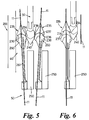
- the latch means 35 is in the form of a latch body 235 fixed to the heald rod 11, the latch body 235 having downwardly facing inclined latch abutment faces 236 projecting both sides of the heald rod 11.
- the cam body 260 has an upwardly facing abutment seat 237 upon which latch faces 236 abut under the bias of spring 17 (not shown).
- the seat 237 covers latch faces 236 such that upwardly facing latch faces 234 formed on the knife 31, 32 cannot engage therewith.
- the heald rod 11 is formed of a flexible, preferably resilient material, and is guided such that when undeflected, latch body 235 lies in the path of travel of latch faces 234 ( Figure 6).
- the body 260 has side cam faces 238 located below seat 237 which co-operate with cam faces 240 on the knife 31, 32 so as to deflect the heald rod 11 sideways to a deflected non-latch position ( Figure 5) as the knife 31 or 32 descends to its lower position KLL and whilst the heald rod 11 is located at its intermediate position IP.
- heald rod 11 If the heald rod 11 is not selected for raising, ie. it is not retained at its intermediate position IP by retention means 51, then body 250 is able to move towards its lower position SLL carrying the heald rod 11 therewith without latch body 235 latchingly engaging latch 234 due to latch abutment faces 236 being shielded by the cam body 260. If the heald rod 11 is selected for raising, ie. it is retained at its intermediate position IP by retention means 51, then as body 250 moves toward its lower position SLL the cam body 260 separates from latch body 235 and the knife 31, 32. Accordingly the heald rod 11 returns to its undeflected latch position under the influence of its own inherent bias and/or bias of resilient arm 261 such that as the knife 31, 32 rises latching engagement between latch body 235 and latch 234 occurs ( Figure 6).
- the heald rod 11 is preferably formed from a thin strip of resilient material such as spring steel and is guided through an aperture formed in body 260. Guiding of the heald rod 11 through cam body 260 serves to ensure that the latch body 235 is correctly seated upon cam body 260 and ensures positive lateral displacement of the heald rod between its latch and non-latch positions. It is envisaged that heald rod 11 may be formed of a plastics material and that the biasing force for returning the deflected heald rod 11 to its latch position is predominantly provided by the resilient arm 261.
- a third embodiment 300 is illustrated in Figure 7 which is similar to embodiment 200 in that the heald rods 11 are moved sideways in order to effect latching engagement/disengagement between the co-operating latches formed on the knife 31, 32 and heald rod 11. Again, in the third embodiment, the same retention means 51 as described in embodiment 100 is utilised.
- the secondary motive drive means 50 includes an elongate body 350 which is mounted on a frame (not shown) for reciprocal movement in the direction of displacement of the knives 31, 32 and also for reciprocal movement in a direction perpendicular to the displacement of the knives 31, 32.
- the heald rod 11 is provided with a latch body 235 similar to that in embodiment 200 but in addition is provided with a separate stop body 320 which is biased into abutment with body 350 by spring 17 (not shown).
- each heald rod 1-1 is longitudinally guided through a respective aperture formed in the- elongate body 350 such that it is positively moved laterally when the body 350 reciprocates in said perpendicular direction.
- the body 350 when at its lower position SLL resides at a first lateral position (as seen in Figure 8a) whereat the heald rod 11 is guided so as to be located at a non-latch position relative to the knife 31, 32.
- first lateral position as seen in Figure 8a
- latch body 235 is laterally spaced from the knife 31, 32 by a sufficient distance to ensure no latching engagement between latch body 235 and 234 can occur.
- the body 350 remains in the first lateral position as the body 350 begins its return stroke to its lower position SLL. During its return stroke or when at its lower position SLL the body 350 moves laterally (arrow B in Figure 8a) to a second lateral position ( Figures 7, 8b) whereat the heald rod 11 is moved toward the knife 31, 32 to reside at a latch position.
- the body 350 remains at its second lateral position until the body 350 again rises toward its upper position SUL, at which time the body 350 returns to its first lateral position.
- a heald rod 11 is selected for raising ( Figure 8a, 8b), it is retained at its intermediate position by the heald rod retention means 51 so that its latch body 235 is located above the co-operating latch means 234 on the relevant knife 31, 32 and is moved laterally by body 350 into a latch position for engagement with the relevant knife 31, 32 as it rises to its upper position KUL. If a heald rod 11 is not selected for raising, as in the case of heald rod 1 la in Figure 7, then it is not retained at its intermediate position IP and so returns with the body 235 to its lower position HLL.
- the body 350 In order to disengage a heald rod 11 from a knife 31, 32 travelling to its lower position KLL , the body 350 is raised to its SUL position whilst the knife 31, 32 descends, the body 350 being in its first lateral position.
- stop 320 engages body 350 and so transfers support of the heald rod 11 from the knife 31, 32 to the body 350.
- FIG. 9 a further embodiment 400 is illustrated which utilises the same retention means 51 as an embodiment 100 and which relies upon lateral deflection of the heald rod 11 for controlling latch engagement between the relevant knife 31, 32 and heald rod 11.
- each heald rod 11 of a given row is located between a pair of secondary knives 451, 452 which reciprocate between positions SUL, SLL.
- the secondary knives 451, 452 are arranged in respective groups; the knives of each group reciprocating in unison.
- the knives of both groups 451, 452 rise together in unison at the same height and speed from position SLL to position SUL but return to position SLL at different rates.
- the knives in group 451 are arranged to return toward position SLL at a faster rate than knives in group 452 when knives 31 are located at their lowermost position KLL for collecting heald rods 11 and, during the next cycle, knives in group 452 are arranged to return toward position SLL at a faster rate than knives in group 451 when knives 32 are located at their lowermost position KLL for collecting heald rods 11.
- Each heald rod 11 includes a stop body 420 which is biased into engagement with co-operating knives 451, 452.
- the upper edge of knives 451, 452 is defined by inclined cam faces 454 upon which the stop body 420 is normally seated.
- the body 420 has a pair of abutment faces 422 extending in opposite lateral directions for contacting respective faces 454 of neighbouring knives 451, 452.
- faces 422 are inclined also. During the raising stroke of knives 451, 452, both knives rise in unison at the same level.
- heald rods 11 are moved to a lateral non-latch position whereat latch bodies 435 are spaced from the latch formation 434 formed on knife 31. If a heald rod 11 is to be raised to its HUL position, (as in the case of heald rod 11 a in Figure 9), it is retained by the retention means 51 at its intermediate position IP. Thus when knives 451, 452 return to their SLL position, the stop 420 moves clear of faces 454 and the heald rod 11 remains at its undeflected position whereat latch body 435 is located in the path of travel of latch formation 434.
- a heald rod 11 is not to be raised, then as it returns toward its HLL position, it is deflected laterally to a non-latch position whereat it clears the latch formation 434.
- latch formations 434 on knives 31, 32 and latch bodies 435 have co-operating latch abutment faces 438, 439 respectively which are inclined to form cam faces which act to deflect the latch body 435 toward the knife 31 or 32 on which it is carried. This serves to move the latch body 435 to a position whereat it lies outside the path of travel of the adjacent knife 31 or 32.
- a fifth embodiment 500 is illustrated in Figure 10.
- the fifth embodiment 500 is similar to the fourth embodiment 400 except that the knives 451, 452 have upwardly inclined cam faces 554 for engagement with latch bodies 535 formed on the heald rods 11.
- the latch bodies 535 also act as the stop 20.
- the heald rod 11 is laterally deflected to a non-latch position (as in the case of heald rod 11 b in Figure 10).
- both sets of knives 451, 452 are located at their bottom position SLL, the latch body 535 of a given heald rod 11 is seated upon both cam faces 554 of neighbouring knives 451, 452 and so resides at a non-deflected position; the heald rod 11 when seated upon both knives 451, 452 being located at its bottom shed position.
- Each adjacent pair of knives 451 co-operate to deflect a pair of heald rods 11 carried thereby laterally away from a co-operating knife 31 to their non-latch position so that no latching engagement is possible between latch formation 534 on knife 31 and latch bodies 535.
- Each pair of adjacent knives 452 similarly co-operate with a co-operating knife 32.
- a heald rod 11 is selected for raising, (as in the case of heald rod 11 c in Figure 10), it is held at its intermediate position IP by the heald retention means 51 and accordingly as the knives 451 descend, latch body 535 of the selected heald rod 11 is lifted off the supporting cam face 554. The heald rod 11 therefore returns to its non-deflected (latch) position under its inherent bias. The latch body 535 is now located in the path of travel of latch formation 534.
- the latch body 535 has an inclined face 538 which co-operates with inclined seat 539 of the latch formation 534 to move the latch body 535 toward the knife 31 or 32 by which it is carried to a position whereat it lies outside the path of travel of the other knife 31. or 32.
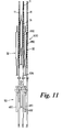
- a further embodiment 600 is illustrated in Figures 11, 12a to 12c.
- Embodiment 600 is similar to embodiment 500 in that the motive means 50 includes two sets of knives 451, 452 which reciprocate 180° out of phase between their respective SUL , SLL positions.
- the heald rods 11 are located at bottom shed positions in readiness for selection. In the embodiment illustrated in Figure 11, the heald rods 11 are held at their bottom shed position by a stop (not shown).
- Each knife 451, 452 includes upwardly facing inclined cam faces 654 arranged to co-operate with downwardly facing inclined cam faces 638 formed on latch bodies 635.
- the cam faces 654, 638 cause the latch bodies 635 to move inwardly toward knife 452 and thereby move the heald rods 11 to their non-latch position. In this position, heald rods 11 can be moved to their IP position without latching engagement with knives 32 ( Figure 12a).
- the latch body 635 is provided with upwardly facing cam faces 639 and the knives 451, 452 are provided with downwardly facing cam faces 640.
- the cam faces 639, 640 are directly opposed when the latch body 635 is carried by the knife 451, 452 such that when the knife 451, 452 descends and the heald rod 11 is held at its IP position, the heald rod 11 is positively displaced by cam faces 639, 640 toward respective knives 32.
- the amount of lateral displacement caused by the opposed cam faces 639, 640 is sufficient to move the heald rod 11 to its latch position whereat a rising knife 32 can latchingly engage the latch body 635 and raise the heald rod 11 to its upper shed position.
- the initial latching engagement between the knife 32 and latch body 635 is shown in Figure 12 b .
- the co-operating opposed cam faces 539, 638 act to move the latch body 635 toward the carrying knife 32 so as to be clear of the neighbouring knife 31 ( Figure 12c).
- the knives 31, 32 are preferably of a pressed metal construction having two identical halves 650 bonded together; the latches 634 being integrally formed with each half.
- each knife 31, 32 has a wide section 651.
- the wide section 651 of each knife is chosen so as to be closely spaced from a latch body 635 of a heald rod 11 held at its upper position. This helps ensure that an adjacent knife 31, 32 rising towards its upper position KUL correctly engages latch body 635 (ie. it is not unintentionally deflected to a non-latch position due to impact of the rising knife onto the latch body 635).
- the heald rods 11 are located at their bottom shed position by a stop (not shown) such that both sets of knives 451, 452 disengage from the latch bodies 635 when they descend to their SUL positions.
- the knives 451, 452 when descending toward their lower limit position SUL dwell for a period of time, in order to define the lower shed position of the heald rods 11 carried thereby.
- Embodiment 600 ensures positive displacement of each heald rod 11 between its latch and non-latch positions. Accordingly, the body of each heald rod 11 does not have to be resiliently deflectable. It is preferable therefore for the heald rods 11 in embodiment 600 to be formed from plastics.
- Embodiment 700 differs in that the heald rods 11 are provided with bodies 740 which co-operate with knives 451, 452 for carrying the heald rods 11 to their IP position and for moving the heald rods 11 between their latch and non-latch position. Accordingly in embodiment 700, latch bodies 635 co-operate with knives 31, 32 only and are not contacted by the knives 451, 452.
- each heald rod 11 is provided with two cam bodies 740a, 740b for co-operation with knives 451, 452 respectively.
- Each cam body 740 a , 740 b has a downwardly facing inclined cam face 742 for co-operation with an upwardly facing inclined cam face 743 formed on the associated knife 451, 452.
- the cam faces 742, 743 are also chamfered so as to resist lateral separation in the longitudinal direction of knives 451, 452 when cam faces 742, 743 are engaged.
- Each cam body 740 also includes an upwardly facing inclined cam face 746 for engagement with a downwardly facing cam face 747 formed on knife 451, 452.
- the cam faces 746, 747 are directly opposed when the cam body 740 is fully seated upon the knife 451, 452 as seen for heald rods 11 a in Figure 13.
- the heald rods 11 are formed of plastics and cam bodies 740 are preferably integrally moulded with the body of the heald rod.
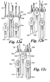
- a further embodiment 800 is illustrated in Figures 14a, b and c.
- Embodiment 800 is similar to embodiment 500 in that the heald rods 11 are carried by the knives 451, 452 between their bottom shed position and IP position and is similar to embodiments 600 and 700 in that cam faces are provided on the heald rods and knives 451, 452 for positively deflecting the heald rods from their non-latch position (heald rod 11b in Figure 14a) to their latch position (heald rod 11c in Figure 14b).
- each knife 451, 452 is provided with fingers 850 spaced along each knife, the finger 850 having the upwardly inclined cam faces 554 for engagement with latch bodies 535 formed on the heald rods.
- the latch bodies 553 have downwardly inclined faces 538 so that when a heald rod 11 is supported by a knife 451, 452 it is located at its non-latch position ( Figure 14a).
- Each heald rod 11 is located between a pair of adjacent fingers 850 and is provided with laterally projecting cam projection 811 located beneath cam faces 538.
- the cam projections 811 have upwardly inclined cam faces 812 which co-operate with downwardly inclined cam faces 814 formed on finger 850 so as to deflect the heald rod 11 to its non-latch position should it be retained at its IP position ( Figure 14b).
- Figure 14c illustrates a heald rod 11d which has been selected and moved to its upper shed position.
- heald rod deflection cam projection 811 By locating the heald rod deflection cam projection 811 below the latch body 535 it is possible to reduce the stroke of knives 451, 452 and enable the lower stroke limit of the upper knives 31, 32 to be located closer to the upper stroke limit of the lower knives 451, 452.
- heald rods 11 for all embodiments include a plurality of latch means 56 spaced along the length of the heald rod body. This enables adjacent rows of heald rods 11 to be retained at different heights and thereby enable inclined sheds to be produced, ie. sheds which taper in the warp direction. Typically, adjacent latch means 56 are spaced 6 mm apart so that a tapered shed will be produced in stepwise manner at intervals of 6 mm.
- neighbouring knives 31 or 32 of each set to be raised by a different height in order to achieve an inclined shed, ie the knife at -the front of the set of knives will be raised by a different height to the knife at the rear of the set of knives.
- a given knife in a set needs to raise a row of heald rods 11 to a predetermined height to enable latch body 153 to latch with a predetermined latch means 56.
- C 1 and C 2 are each at least 1.5 mm.
- the present invention utilises a single retention means 51 wherein latch body 153 needs to co-operate both with latch means 52 (for selection of a heald rod 11 for raising to its upper shed position) and with a predetermined latch means 56 for retaining heald rod 11 at its upper shed position.
- latch means 52 are provided which are spaced apart by a different pitch spacing to the pitch spacing between latch means 56, for example the spacing between latch means 52 may be 1 1/2 times the spacing between latch means 56 ie in the typical example, the spacing between latch means 52 is 9 mm.
- each row of latch bodies 153 to be located at two distinct heights (an upper height and a lower height spaced 9 mm apart) whereby the latch bodies 153 in a given row co-operate with one or other of the latch means 52. In this way the latch bodies 153 act to retain heald rods 11 in all rows at the same height.
- the height of a row of latch bodies 153 is such that the clearance criteria for C 1 or C 2 is not possible due to the degree of lift of the associated knives 31, 32, then it is possible to move the latch bodies 153 from one height setting (say upper) to the other height setting (say lower) or vice versa. This has the affect of locating the latch bodies 153 in the row for co-operation with the next pair of latch means 56 and since the latch bodies 153 have been displaced by 9 mm and the latch means 56 are spaced 6 mm apart, the criteria for C 1 or C 2 is now met.
- FIG. 16 shows a suitable heald rod 11 having 5 latch means 52 having a pitch spacing of 9 mm and 10 latch means 56 having a pitch spacing of 12 mm.
Applications Claiming Priority (2)
| Application Number | Priority Date | Filing Date | Title |
|---|---|---|---|
| GB9609425 | 1996-05-04 | ||
| GBGB9609425.5A GB9609425D0 (en) | 1996-05-04 | 1996-05-04 | Heald control mechanism |
Publications (2)
| Publication Number | Publication Date |
|---|---|
| EP0808925A1 true EP0808925A1 (de) | 1997-11-26 |
| EP0808925B1 EP0808925B1 (de) | 2002-09-04 |
Family
ID=10793247
Family Applications (1)
| Application Number | Title | Priority Date | Filing Date |
|---|---|---|---|
| EP97302950A Expired - Lifetime EP0808925B1 (de) | 1996-05-04 | 1997-04-30 | Vorrichtung zur Litzensteuerung |
Country Status (7)
| Country | Link |
|---|---|
| EP (1) | EP0808925B1 (de) |
| JP (1) | JP4091141B2 (de) |
| KR (1) | KR970075006A (de) |
| CN (1) | CN1068643C (de) |
| DE (1) | DE69715087T2 (de) |
| GB (1) | GB9609425D0 (de) |
| TW (1) | TW359696B (de) |
Families Citing this family (3)
| Publication number | Priority date | Publication date | Assignee | Title |
|---|---|---|---|---|
| FR2900666B1 (fr) * | 2006-05-03 | 2008-06-20 | Staubli Lyon Soc Par Actions S | Mecanisme de formation de la foule, metier a tisser equipe d'un tel mecanisme et procede de selection des crochets mobiles d'un tel mecanisme |
| CN105350167B (zh) * | 2015-11-30 | 2017-01-25 | 浙江日发纺织机械股份有限公司 | 一种自动穿经机的经纱供给及切换机构 |
| CN109371549B (zh) * | 2018-12-07 | 2021-03-19 | 福建伟易泰智能科技有限公司 | 一种综眼高度自动调节装置及穿经机 |
Citations (3)
| Publication number | Priority date | Publication date | Assignee | Title |
|---|---|---|---|---|
| EP0135074A2 (de) * | 1983-08-12 | 1985-03-27 | FIMTESSILE FABBRICA ITALIANA MACCHINARIO TESSILE S.p.A. | Stangenförmige Platine für eine Jacquardmaschine und damit ausgerüstete Maschine |
| EP0512587A1 (de) * | 1991-05-03 | 1992-11-11 | Ets. Richard Wittendal S.A. | Platinenwahlverfahren für eine Jacquardmaschine sowie Platinen für eine derartige Maschine |
| EP0711856A2 (de) * | 1994-11-08 | 1996-05-15 | Bonas Machine Company Limited | Vorrichtung zur Litzensteuerung |
Family Cites Families (6)
| Publication number | Priority date | Publication date | Assignee | Title |
|---|---|---|---|---|
| CH586768A5 (de) * | 1975-01-31 | 1977-04-15 | Sulzer Ag | |
| US4041987A (en) * | 1976-08-23 | 1977-08-16 | Sulzer Brothers Limited | Jacquard machine equipped with lifting wires and stationary arresting blades |
| JPS56156875U (de) * | 1980-04-16 | 1981-11-24 | ||
| FR2586432B1 (fr) * | 1985-08-23 | 1987-11-13 | Staubli Verdol | Dispositif pour la formation de la foule d'un metier a tisser |
| DE3713832C1 (de) * | 1987-04-24 | 1988-06-23 | Grosse Webereimaschinen Gmbh | Platinen-Steuervorrichtung fuer Offenfach-Jacquardmaschine |
| GB8827141D0 (en) * | 1988-11-21 | 1988-12-29 | Bonas Machine Co | Heald control device |
-
1996
- 1996-05-04 GB GBGB9609425.5A patent/GB9609425D0/en active Pending
- 1996-05-14 TW TW085105641A patent/TW359696B/zh active
-
1997
- 1997-04-30 DE DE69715087T patent/DE69715087T2/de not_active Expired - Lifetime
- 1997-04-30 EP EP97302950A patent/EP0808925B1/de not_active Expired - Lifetime
- 1997-05-03 KR KR1019970017144A patent/KR970075006A/ko not_active Application Discontinuation
- 1997-05-04 CN CN97113062A patent/CN1068643C/zh not_active Expired - Fee Related
- 1997-05-06 JP JP11589797A patent/JP4091141B2/ja not_active Expired - Lifetime
Patent Citations (3)
| Publication number | Priority date | Publication date | Assignee | Title |
|---|---|---|---|---|
| EP0135074A2 (de) * | 1983-08-12 | 1985-03-27 | FIMTESSILE FABBRICA ITALIANA MACCHINARIO TESSILE S.p.A. | Stangenförmige Platine für eine Jacquardmaschine und damit ausgerüstete Maschine |
| EP0512587A1 (de) * | 1991-05-03 | 1992-11-11 | Ets. Richard Wittendal S.A. | Platinenwahlverfahren für eine Jacquardmaschine sowie Platinen für eine derartige Maschine |
| EP0711856A2 (de) * | 1994-11-08 | 1996-05-15 | Bonas Machine Company Limited | Vorrichtung zur Litzensteuerung |
Also Published As
| Publication number | Publication date |
|---|---|
| JPH1046450A (ja) | 1998-02-17 |
| KR970075006A (ko) | 1997-12-10 |
| EP0808925B1 (de) | 2002-09-04 |
| TW359696B (en) | 1999-06-01 |
| DE69715087D1 (de) | 2002-10-10 |
| CN1068643C (zh) | 2001-07-18 |
| GB9609425D0 (en) | 1996-07-10 |
| DE69715087T2 (de) | 2003-04-17 |
| JP4091141B2 (ja) | 2008-05-28 |
| CN1178266A (zh) | 1998-04-08 |
Similar Documents
| Publication | Publication Date | Title |
|---|---|---|
| EP0119787B1 (de) | Litzensteuervorrichtung | |
| US5133389A (en) | Solenoid-controlled heald rod system | |
| KR100905251B1 (ko) | 횡편기의 급사장치 및 횡편기의 급사방법 | |
| EP0457811B1 (de) | System zum rückhalten einer litzenstange zur verwendung in einem elektrisch gesteuerten jacquardmaschinensystem | |
| EP0188074A1 (de) | Litzensteuervorrichtung | |
| EP0808925B1 (de) | Vorrichtung zur Litzensteuerung | |
| EP0711856B1 (de) | Vorrichtung zur Litzensteuerung | |
| US5743308A (en) | Double lift weave system | |
| JP3568635B2 (ja) | たわみ素子手段により複数の開口装置の選択を行うための機構 | |
| EP3495537B1 (de) | Fachbildevorrichtung für eine webmaschine | |
| EP0330624A2 (de) | Doppelfachwebmaschine mit verbessertem Hakensteuerungssystem | |
| CN1030932C (zh) | 纺织机械用的开口装置 | |
| KR880001204B1 (ko) | 루우프성형 조립체 | |
| US5464046A (en) | Electrically controlled jacquard selection apparatus | |
| US5483995A (en) | Device for coupling and uncoupling loom heald shafts | |
| EP0658223B1 (de) | Litzensteuervorrichtung | |
| WO1999011850A2 (en) | Electronic jacquard mechanism for a weaving loom | |
| EP0439440A1 (de) | Elektromagnetische modulare, computergesteuerte Kettfadensteuervorrichtung für die Bildweberei | |
| JPS6245745A (ja) | 織機のひ口形成装置のための可動フツクの改良 | |
| JP2001329445A (ja) | ジャカード機の選針装置 | |
| EP1357210A1 (de) | Nadelselektor für jacquardmaschine | |
| JPH0784689B2 (ja) | ジャカード機の経糸選択制御装置 | |
| CS243459B2 (en) | Double-lifting jacquard machine for open shed | |
| EP0371134A1 (de) | Transfervorrichtung für geladene und leere bobinen für spinnmaschinen |
Legal Events
| Date | Code | Title | Description |
|---|---|---|---|
| PUAI | Public reference made under article 153(3) epc to a published international application that has entered the european phase |
Free format text: ORIGINAL CODE: 0009012 |
|
| AK | Designated contracting states |
Kind code of ref document: A1 Designated state(s): BE CH DE FR GB IT LI |
|
| 17P | Request for examination filed |
Effective date: 19980521 |
|
| 17Q | First examination report despatched |
Effective date: 20000321 |
|
| GRAG | Despatch of communication of intention to grant |
Free format text: ORIGINAL CODE: EPIDOS AGRA |
|
| GRAG | Despatch of communication of intention to grant |
Free format text: ORIGINAL CODE: EPIDOS AGRA |
|
| GRAH | Despatch of communication of intention to grant a patent |
Free format text: ORIGINAL CODE: EPIDOS IGRA |
|
| GRAH | Despatch of communication of intention to grant a patent |
Free format text: ORIGINAL CODE: EPIDOS IGRA |
|
| GRAA | (expected) grant |
Free format text: ORIGINAL CODE: 0009210 |
|
| AK | Designated contracting states |
Kind code of ref document: B1 Designated state(s): BE CH DE FR GB IT LI |
|
| REG | Reference to a national code |
Ref country code: GB Ref legal event code: FG4D |
|
| REG | Reference to a national code |
Ref country code: CH Ref legal event code: EP |
|
| REF | Corresponds to: |
Ref document number: 69715087 Country of ref document: DE Date of ref document: 20021010 |
|
| REG | Reference to a national code |
Ref country code: CH Ref legal event code: NV Representative=s name: R. A. EGLI & CO. PATENTANWAELTE |
|
| RAP2 | Party data changed (patent owner data changed or rights of a patent transferred) |
Owner name: BONAS MACHINE COMPANY LIMITED |
|
| ET | Fr: translation filed | ||
| PLBE | No opposition filed within time limit |
Free format text: ORIGINAL CODE: 0009261 |
|
| STAA | Information on the status of an ep patent application or granted ep patent |
Free format text: STATUS: NO OPPOSITION FILED WITHIN TIME LIMIT |
|
| 26N | No opposition filed |
Effective date: 20030605 |
|
| PGFP | Annual fee paid to national office [announced via postgrant information from national office to epo] |
Ref country code: DE Payment date: 20120502 Year of fee payment: 16 Ref country code: BE Payment date: 20120412 Year of fee payment: 16 Ref country code: CH Payment date: 20120412 Year of fee payment: 16 |
|
| PGFP | Annual fee paid to national office [announced via postgrant information from national office to epo] |
Ref country code: FR Payment date: 20120504 Year of fee payment: 16 Ref country code: GB Payment date: 20120425 Year of fee payment: 16 |
|
| PGFP | Annual fee paid to national office [announced via postgrant information from national office to epo] |
Ref country code: IT Payment date: 20120421 Year of fee payment: 16 |
|
| BERE | Be: lapsed |
Owner name: *BONAS MACHINE CY LTD Effective date: 20130430 |
|
| REG | Reference to a national code |
Ref country code: CH Ref legal event code: PL |
|
| GBPC | Gb: european patent ceased through non-payment of renewal fee |
Effective date: 20130430 |
|
| PG25 | Lapsed in a contracting state [announced via postgrant information from national office to epo] |
Ref country code: GB Free format text: LAPSE BECAUSE OF NON-PAYMENT OF DUE FEES Effective date: 20130430 Ref country code: LI Free format text: LAPSE BECAUSE OF NON-PAYMENT OF DUE FEES Effective date: 20130430 Ref country code: DE Free format text: LAPSE BECAUSE OF NON-PAYMENT OF DUE FEES Effective date: 20131101 Ref country code: CH Free format text: LAPSE BECAUSE OF NON-PAYMENT OF DUE FEES Effective date: 20130430 Ref country code: BE Free format text: LAPSE BECAUSE OF NON-PAYMENT OF DUE FEES Effective date: 20130430 |
|
| REG | Reference to a national code |
Ref country code: FR Ref legal event code: ST Effective date: 20131231 |
|
| PG25 | Lapsed in a contracting state [announced via postgrant information from national office to epo] |
Ref country code: IT Free format text: LAPSE BECAUSE OF NON-PAYMENT OF DUE FEES Effective date: 20130430 Ref country code: FR Free format text: LAPSE BECAUSE OF NON-PAYMENT OF DUE FEES Effective date: 20130430 |
|
| REG | Reference to a national code |
Ref country code: DE Ref legal event code: R119 Ref document number: 69715087 Country of ref document: DE Effective date: 20131101 |