EP0808737B1 - Dashboard for a motor vehicle - Google Patents
Dashboard for a motor vehicle Download PDFInfo
- Publication number
- EP0808737B1 EP0808737B1 EP97105330A EP97105330A EP0808737B1 EP 0808737 B1 EP0808737 B1 EP 0808737B1 EP 97105330 A EP97105330 A EP 97105330A EP 97105330 A EP97105330 A EP 97105330A EP 0808737 B1 EP0808737 B1 EP 0808737B1
- Authority
- EP
- European Patent Office
- Prior art keywords
- dashboard
- sound
- layers
- motor vehicle
- proofing
- Prior art date
- Legal status (The legal status is an assumption and is not a legal conclusion. Google has not performed a legal analysis and makes no representation as to the accuracy of the status listed.)
- Expired - Lifetime
Links
Images
Classifications
-
- B—PERFORMING OPERATIONS; TRANSPORTING
- B60—VEHICLES IN GENERAL
- B60H—ARRANGEMENTS OF HEATING, COOLING, VENTILATING OR OTHER AIR-TREATING DEVICES SPECIALLY ADAPTED FOR PASSENGER OR GOODS SPACES OF VEHICLES
- B60H1/00—Heating, cooling or ventilating [HVAC] devices
- B60H1/00507—Details, e.g. mounting arrangements, desaeration devices
- B60H1/00557—Details of ducts or cables
- B60H1/00564—Details of ducts or cables of air ducts
-
- B—PERFORMING OPERATIONS; TRANSPORTING
- B60—VEHICLES IN GENERAL
- B60H—ARRANGEMENTS OF HEATING, COOLING, VENTILATING OR OTHER AIR-TREATING DEVICES SPECIALLY ADAPTED FOR PASSENGER OR GOODS SPACES OF VEHICLES
- B60H1/00—Heating, cooling or ventilating [HVAC] devices
- B60H1/00507—Details, e.g. mounting arrangements, desaeration devices
- B60H1/00514—Details of air conditioning housings
- B60H1/0055—Details of air conditioning housings the housing or parts thereof being integrated in other devices, e.g. dashboard
-
- B—PERFORMING OPERATIONS; TRANSPORTING
- B60—VEHICLES IN GENERAL
- B60H—ARRANGEMENTS OF HEATING, COOLING, VENTILATING OR OTHER AIR-TREATING DEVICES SPECIALLY ADAPTED FOR PASSENGER OR GOODS SPACES OF VEHICLES
- B60H1/00—Heating, cooling or ventilating [HVAC] devices
- B60H1/24—Devices purely for ventilating or where the heating or cooling is irrelevant
- B60H1/241—Devices purely for ventilating or where the heating or cooling is irrelevant characterised by the location of ventilation devices in the vehicle
- B60H1/242—Devices purely for ventilating or where the heating or cooling is irrelevant characterised by the location of ventilation devices in the vehicle located in the front area
-
- B—PERFORMING OPERATIONS; TRANSPORTING
- B60—VEHICLES IN GENERAL
- B60K—ARRANGEMENT OR MOUNTING OF PROPULSION UNITS OR OF TRANSMISSIONS IN VEHICLES; ARRANGEMENT OR MOUNTING OF PLURAL DIVERSE PRIME-MOVERS IN VEHICLES; AUXILIARY DRIVES FOR VEHICLES; INSTRUMENTATION OR DASHBOARDS FOR VEHICLES; ARRANGEMENTS IN CONNECTION WITH COOLING, AIR INTAKE, GAS EXHAUST OR FUEL SUPPLY OF PROPULSION UNITS IN VEHICLES
- B60K37/00—Dashboards
- B60K37/20—Dashboard panels
Definitions
- the invention relates to a dashboard for a motor vehicle according to the Preamble of claim 1.
- a dashboard from two fitting parts, each of which has molded-on walls to form a channel.
- This channel is used to hold components of the ventilation and heating system, for example to hold air duct connections between a heating or air conditioning system and the corresponding outlet nozzles.
- a disadvantage of the known dashboard is that to form the channels, the dashboard parts are essentially formed with vertical walls of thin wall thickness. It is therefore necessary for the fitting parts to be shaped precisely so that the corresponding contact surfaces of the adjacent fitting parts lie essentially flush with one another. In addition, a large amount of installation work is necessary because the individual components of the heating or ventilation system have to be inserted into recesses provided for this purpose.
- a dashboard is known from DE 44 23 108, which consists of an upper and a lower part made of a polypropylene foam is. Cavities are formed between the upper and lower part for air guidance are usable.
- the invention has for its object to design a dashboard such that air ducts within a dashboard in a simple way and can be formed in any form.
- the invention has the characterizing features of claim 1 on.
- the dashboard has soundproofing layers a sound-absorbing material, which is arranged in layers one above the other are.
- the soundproofing layers stacked on top of each other Recesses and / or openings so that any shape or any cross section of the air channels can be achieved.
- the heating or air conditioning system effectively attenuates the sound.
- the dashboard completely with these Soundproofing layers filled.
- this enables layers Arrangement of the soundproofing layers that the air channels in can extend in any direction. It is no longer necessary, in addition Route air duct connections within the dashboard.
- the fact that the dashboard is essentially completely with the sound absorbing material is filled and only openings and Has recesses, an increased dimensional stability of the dashboard be achieved.
- the soundproofing layers can be produced as foamed molded parts and are attached to the upper fitting part.
- the fitting parts and / or soundproofing layers made of a foamed plastic, in particular from an expanded polypropylene material.
- a foamed plastic in particular from an expanded polypropylene material.
- more tough elastic Rigid foam ensures this material has an increased cross and Longitudinal rigidity of the dashboard.
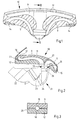
- Fig. 1 shows the outline of a dashboard 10 in which a plurality of air duct channels are arranged.
- the dashboard 10 has an upper fitting part 11 and a lower fitting part 12.
- These fitting parts 11, 12 consist of a foamed plastic, preferably of an expanded polypropylene (EPP).
- EPP expanded polypropylene
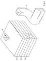
- the dashboard parts 11 and 12 form an interior of the dashboard 10, which, as shown in FIGS. 4 and 5, is filled by several layers of horizontal sound-absorbing layers 30.
- the sound damping layers' 30 consist of a sound damping material.
- the soundproofing layers 30 have a relatively thin wall thickness, so that with a corresponding number of stacked soundproofing layers 30 an air duct 31 is formed which not only conducts a continuous airflow in one plane, but also ensures a continuous airflow in any direction.
- the air duct 31 can run downward in a three-dimensional direction from an upper corner region of the uppermost soundproofing layer 30 and, after a deflection of 90 °, can run parallel to a longitudinal center plane of the soundproofing layers 30 to a lateral region .
- the two uppermost sound damping layers 30 each have an opening 32 and 33, the sound damping layers 30 being placed one above the other in a substantially flush relationship with the openings 32 and 33.
- the openings 32 and 33 have the shape of a circular sector.
- the second uppermost sound damping layer 30 has on its underside a wedge-shaped recess 34, the course of which corresponds to the course of a recess 35 of the adjacent sound damping layer 30 which adjoins at the bottom.
- the recess 35 widens downwards in cross-section in a wedge shape and has the same angular shape as a recess 36 of the sound-damping layer 30 which adjoins at the bottom.
- a further sound-damping layer 30 which adjoins at the bottom has a recess 37. so that the air duct 31 is formed after the composition of the sound damping layers 30, the course of which is shown in FIG. 4.
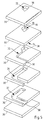
- the Soundproofing layers 30 consist of a soundproofing material, preferably made of an open-cell foam. This can be as foamed plastic, be designed as PE foam or PU foam.
- the soundproofing layers 30 are placed one above the other and laterally held together by suitable fasteners. Below will be it is attached to the lower side of the upper dashboard 11.
- the soundproofing layers 30 can also be made from a different one Material exist, so that a targeted influence on the to be damped Sound frequency can be carried out. To do this, corresponding Materials with different sound absorbing properties selected be dependent on the location of the sound source or the course of the sound within the layer structure of the sound absorption layers 30 are arranged. By increasing the number of soundproofing layers 30 also the continuity or uniformity of the Airflow - without sharp edges leading to turbulence - increases. This leads to a further reduction in the noise carried in the air flow. In addition, such a multilayer arrangement enables Soundproofing layers 30 that air channels run in any direction can. For example, air ducts can be offset in height cross. This enables a space-saving construction of the dashboard.
- the openings 32, 33 have the recesses 34, 37 and the cutouts 35, 36 a thin skin layer 38 on, each after making the individual soundproofing layers 30 is applied.
- the skin layer 38 preferably consists made of a non-woven material.
- air channels 9 are formed be that of an entry area 13 of the dashboard 10, which is located on an underside of the lower fitting part 12, towards each a laterally arranged side nozzle outlet opening 14 to one itself forwardly extending central nozzle outlet opening 15 and several Defroster outlet openings arranged in the region of a windshield 16 17.
- the air duct 9 extends to the defroster outlet opening 17 is essentially concave in the direction of the windshield 16, the cross section of this channel 9 being in the region of the defroster nozzle outlet opening 17 narrowed.
- An air conditioning unit 21 is fixed to the dashboard below the entry area 13 10 connected.
- the air conditioning system 21 is known per se Formed and has an evaporator 22 and a heater 23rd on, by means of a mixing flap 24, the temperature of the through the outlet openings 25 of the air conditioning system 21 passed air flow becomes.
- an outlet connection 26 on the side provided, through which an air flow in the direction of the footwell outlet nozzles, not shown is derived.
- the dash parts 11 and 12 can be easily Manufacture way as molded parts.
- the fact that the dashboard 10th is almost completely filled with a foamed plastic - with the exception the air channels 9 or other channels for electrical cables - is created a compact shape that is also sound absorbing works.
- the fittings 11 and 12 can be shaped so that a transverse - Not shown - cross member is extrusion-coated, so that a sufficient Transverse rigidity of the vehicle is guaranteed.
Landscapes
- Engineering & Computer Science (AREA)
- Mechanical Engineering (AREA)
- Physics & Mathematics (AREA)
- Thermal Sciences (AREA)
- Chemical & Material Sciences (AREA)
- Combustion & Propulsion (AREA)
- Transportation (AREA)
- Instrument Panels (AREA)
- Air-Conditioning For Vehicles (AREA)
- Vehicle Interior And Exterior Ornaments, Soundproofing, And Insulation (AREA)
Description
Die Erfindung betrifft ein Armaturenbrett für ein Kraftfahrzeug nach dem Oberbegriff des Patentanspruchs 1.The invention relates to a dashboard for a motor vehicle according to the Preamble of claim 1.
Aus der EP 0 185 856 B1 ist es bekannt, ein Armaturenbrett aus zwei Armaturenteilen auszubilden, die jeweils angeformte Wände aufweisen zur Bildung eines Kanals. Dieser Kanal dient zur Aufnahme von Komponenten der Belüftungs- und Heizungsanlage, beispielsweise zur Aufnahme von Luftführungsverbindungen zwischen einer Heizungs- oder Klimaanlage und den entsprechenden Austrittsdüsen. Nachteilig an dem bekannten Armaturenbrett ist, daß zur Ausbildung der Kanäle den Armaturenteilen im wesentlichen senkrechte Wände dünner Wandstärke angeformt sind. Es ist daher eine passgenaue Ausformung der Armaturenteile erforderlich, damit die korrespondierenden Anlageflächen der benachbarten Armaturenteile im wesentlichen bündig aneinanderliegen. Weiterhin ist ein großer Montageaufwand notwendig, weil die einzelnen Komponenten der Heizungs- bzw. Belüftungsanlage in dafür vorgesehene Aussparungen eingesetzt werden müssen. From EP 0 185 856 B1 it is known to form a dashboard from two fitting parts, each of which has molded-on walls to form a channel. This channel is used to hold components of the ventilation and heating system, for example to hold air duct connections between a heating or air conditioning system and the corresponding outlet nozzles. A disadvantage of the known dashboard is that to form the channels, the dashboard parts are essentially formed with vertical walls of thin wall thickness. It is therefore necessary for the fitting parts to be shaped precisely so that the corresponding contact surfaces of the adjacent fitting parts lie essentially flush with one another. In addition, a large amount of installation work is necessary because the individual components of the heating or ventilation system have to be inserted into recesses provided for this purpose.
Aus der DE 44 23 108 ist ein Armaturenbrett bekannt, das aus einem Ober- und einem Unterteil, die aus einem Polypropylenschaum bestehen, gebildet ist. Zwischen Ober- und Unterteil sind Hohlräume gebildet, die zur Luftführung nutzbar sind.A dashboard is known from DE 44 23 108, which consists of an upper and a lower part made of a polypropylene foam is. Cavities are formed between the upper and lower part for air guidance are usable.
Der Erfindung liegt die Aufgabe zugrunde, ein Armaturenbrett derart auszubilden, daß Luftkanäle innerhalb eines Armaturenbrettes auf einfache Weise und in beliebiger Form gebildet werden können.The invention has for its object to design a dashboard such that air ducts within a dashboard in a simple way and can be formed in any form.
Zur Lösung der Aufgabe weist die Erfindung die kennzeichnenden Merkmale des Anspruchs 1 auf.To achieve the object, the invention has the characterizing features of claim 1 on.
Erfindungsgemäß weist das Armaturenbrett Schalldämpfungsschichten aus einem schalldämpfenden Werkstoff auf, die schichtweise übereinander angeordnet sind. Die aufeinander gestapelten Schalldämpfungsschichten weisen Ausnehmungen und/oder Öffnungen auf, so daß eine beliebige Form bzw. ein beliebiger Querschnitt der Luftkanäle erzielt werden kann. Durch Vorsehen mehrerer solcher Schalldämpfungschichten ist es möglich, mehrere übereinander angeordnete Luftkanäle, die sich in verschiedene Richtungen erstrecken, auszubilden. Es wird zum einen der bei Betrieb einer Heizungs- oder Klimaanlage entstehende Schall wirksam gedämpft. Zu diesem Zweck ist das Armaturenbrett vorzugsweise vollständig mit diesen Schalldämpfungsschichten ausgefüllt. Zum anderen ermöglicht die lagenweise Anordnung der Schalldämpfungsschichten, daß sich die Luftkanäle in beliebiger Richtung erstrecken können. Es ist nicht mehr notwendig, zusätzlich Luftführungsverbindungen innerhalb des Armaturenbretts zu verlegen. Dadurch, daß das Armaturenbrett im wesentlichen vollständig mit dem schallabsorbierenden Werkstoff ausgefüllt ist und lediglich Öffnungen und Ausnehmungen aufweist, kann eine vergrößerte Formstabilität des Armaturenbretts erzielt werden. According to the invention, the dashboard has soundproofing layers a sound-absorbing material, which is arranged in layers one above the other are. The soundproofing layers stacked on top of each other Recesses and / or openings so that any shape or any cross section of the air channels can be achieved. By Providing several such sound absorption layers, it is possible to have several air ducts arranged one above the other, extending in different directions extend to train. On the one hand it becomes the one in operation The heating or air conditioning system effectively attenuates the sound. To this Purpose is preferably the dashboard completely with these Soundproofing layers filled. On the other hand, this enables layers Arrangement of the soundproofing layers that the air channels in can extend in any direction. It is no longer necessary, in addition Route air duct connections within the dashboard. The fact that the dashboard is essentially completely with the sound absorbing material is filled and only openings and Has recesses, an increased dimensional stability of the dashboard be achieved.
Die Schalldämpfungsschichten sind als geschäumte Formteile herstellbar und werden an dem oberen Armaturenteil befestigt. Vorzugsweise bestehen die Schalldämpfungsschichten aus einem flexiblen, offenporigen Schaumstoff.The soundproofing layers can be produced as foamed molded parts and are attached to the upper fitting part. Preferably exist the soundproofing layers made of a flexible, open-cell foam.
Nach einer Ausgestaltung der Erfindung bestehen die Armaturenteile und/oder Schalldämpfungsschichten aus einem geschäumten Kunststoff, insbesondere aus einem expandierten Polypropylen-Werkstoff. Als zähelastischer Hartschaum gewährleistet dieser Werkstoff eine erhöhte Quer- und Längssteifigkeit des Armaturenbretts.According to one embodiment of the invention, the fitting parts and / or soundproofing layers made of a foamed plastic, in particular from an expanded polypropylene material. As more tough elastic Rigid foam ensures this material has an increased cross and Longitudinal rigidity of the dashboard.
Auf einfache Weise wird mit der Erfindung die Montage einer kompakten Heizungs- oder Klimaanlage an ein luftkanalführendes Armaturenbrett ermöglicht, wobei lediglich die Öffnungen des Austrittsstutzens der Heizungs- oder Klimaanlage und die Eintrittsöffnungen des Armaturenbretts zueinander korrespondieren müssen. Mit geringem Montageaufwand kann zum einen eine Heizungs- oder Klimaanlage hergestellt und zum anderen ein integrierte Luftführungskanäle aufweisendes Armaturenbrett hergestellt und miteinander verbunden werden. An den Austrittsöffnungen brauchen lediglich entsprechende Austrittsdüsenelemente eingepaßt werden.The assembly of a compact is simple with the invention Allows heating or air conditioning to an air duct leading dashboard, only the openings of the outlet connection of the heating or air conditioning and the inlet openings of the dashboard to each other have to correspond. On the one hand, with little installation effort a heating or air conditioning system and an integrated one Dashboard with air ducts made and with each other get connected. At the outlet openings only need corresponding outlet nozzle elements are fitted.
Ein Ausführungsbeispiel der Erfindung wird nachstehend anhand der Zeichnungen näher erläutert. Es zeigen:
- Fig. 1
- Eine perspektivische Darstellung eines Armaturenbretts;
- Fig. 2
- einen Schnitt durch das Armaturenbrett nach Fig. 1 entlang der Linie II-II;
- Fig. 4
- eine perspektivische Darstellung eines Blockes mehrerer Lagen von Schalldämpfungsschichten, der an einem oberen Armaturenteil befestigt wird, sowie einen Ausschnitt eines durch den Block verlaufenden Luftkanals und
- Fig. 5
- eine perspektivische Darstellung mehrerer Schalldämpfungsschichten, die im zusammengesetzten Zustand den Block nach Fig. 4 darstellen.
- Fig. 1
- A perspective view of a dashboard;
- Fig. 2
- a section through the dashboard of Figure 1 along the line II-II.
- Fig. 4
- a perspective view of a block of several layers of soundproofing layers, which is attached to an upper fitting part, and a section of an air duct running through the block and
- Fig. 5
- a perspective view of several soundproofing layers, which in the assembled state represent the block of FIG. 4.
Fig. 1 zeigt die Umrisse eines Armaturenbretts 10, in dem mehrere Luftführungskanäle
angeordnet sind. Das Armaturenbrett 10 weist ein oberes Armaturenteil
11 und ein unteres Armaturenteil 12 auf. Diese Armaturenteile
11, 12 bestehen aus einem geschäumten Kunststoff, vorzugsweise aus einem
expandierten Polypropylen (EPP). Die Armaturenteile 11 und 12 bilden
nach dem Zusammensetzen einen Innenraum des Armaturenbretts 10, der
wie in Fig. 4 und Fig. 5 dargestellt durch mehrere Lagen waagerechter
Schalldämpfungsschichten 30 ausgefüllt ist. Die Schalldämpfungsschichten '
30 bestehen aus einem schalldämpfenden Material. Die Schalldämpfungsschichten
30 weisen eine relativ dünne Wandstärke auf, so daß bei einer
entsprechenden Anzahl aufeinander gestapelten Schalldämpfungsschichten
30 ein Luftkanal 31 gebildet wird, der nicht nur einen kontinuierlichen Luftstrom
in einer Ebene leitet, sondern darüber hinaus einen kontinuierlichen
Luftstrom in beliebiger Richtung gewährleistet. Fig. 1 shows the outline of a
Wie aus Fig. 4 und Fig. 5 zu ersehen ist, kann der Luftkanal 31 in dreidimensionaler
Richtung von einem oberen Eckbereich der obersten Schalldämpfungsschicht
30 bogenförmig nach unten verlaufen und nach einer
Umlenkung von 90ø parallel zu einer Längsmittelebene der Schalldämpfungsschichten
30 zu einem seitlichen Bereich verlaufen. Zu diesem Zweck
weisen die beiden obersten Schalldämpfungsschichten 30 jeweils eine Öffnung
32 bzw. 33 auf, wobei die Schalldämpfungsschichten 30 im wesentlichen
fluchtend zu den Öffnungen 32 und 33 übereinandergelegt sind. Die
Öffnungen 32 und 33 haben die Form eines Kreissektors. Die zweitoberste
Schalldämpfungsschicht 30 weist an ihrer Unterseite eine keilförmige Ausnehmung
34 auf, deren Verlauf zu dem Verlauf einer Aussparung 35 der
sich nach unten hin anschließenden benachbarten Schalldämpfungsschicht
30 korrespondiert. Die Aussparung 35 weitet sich nach unten hin im Querschnitt
keilförmig auf und weist den gleichen winkelförmigen Verlauf auf wie
eine Aussparung 36 der sich nach unten hin anschließenden Schalldämpfungsschicht
30. Eine weitere Schalldämpfungsschicht 30, die sich nach
unten hin anschließt, weist eine Ausnehmung 37 auf, so daß nach Zusammensetzung
der Schalldämpfungsschichten 30 der Luftkanal 31 gebildet ist,
dessen Verlauf in Fig. 4 dargestellt ist.As can be seen from FIG. 4 and FIG. 5 , the
Durch das Aufeinanderschichten einer gewissen Anzahl von Schalldämpfungsschichten
30 ist somit ein Luftkanal 31 ausgebildet, der bei einem kontinuierlichen
Verlauf je nach den Erfordernissen in beliebiger Richtung verlaufen
kann. Zu diesem Zweck müssen die Schichten lediglich mit entsprechenden
Prägungen oder Stanzungen versehen werden zur Ausbildung der
Öffnungen 32, 33, Ausnehmungen 34, 37 und Aussparungen 35, 36. Die
Schalldämpfungsschichten 30 bestehen aus einem schalldämpfenden Material,
vorzugsweise aus einem offenporigen Schaumstoff. Dieser kann als
geschäumter Kunststoff, als PE-Schaum oder PU-Schaum ausgebildet sein.
Die Schalldämpfungsschichten 30 werden übereinander gelegt und seitlich
durch geeignete Befestigungsmittel zusammengehalten. Nachfolgend werden
sie untenseitig an dem oberen Armaturenbrett 11 befestigt. By stacking a certain number of soundproofing layers on top of each other
30 is thus formed an
Die Schalldämpfungsschichten 30 können auch aus einem unterschiedlichen
Material bestehen, so daß eine gezielte Beeinflussung der zu dämpfenden
Schallfrequenz durchgeführt werden kann. Dazu müssen entsprechende
Materialien unterschiedlicher schallabsorbierender Eigenschaften ausgewählt
werden, die in Abhängigkeit vom Ort der Schallquelle bzw. vom Verlauf
des Schalls innerhalb des Schichtaufbaus der Schalldämpfungsschichten
30 angeordnet sind. Durch Erhöhung der Anzahl der Schalldämpfungsschichten
30 wird zudem die Kontinuierlichkeit bzw. Gleichmäßigkeit des
Luftstroms - ohne daß scharfe Kanten zur Verwirbelung führen - erhöht. Dies
führt zu einer weiteren Reduktion des im Luftstrom transportierten Geräusches.
Darüber hinaus ermöglicht eine solche mehrlagige Anordnung der
Schalldämpfungsschichten 30, daß Luftkanäle in beliebiger Richtung verlaufen
können. Beispielsweise können sich Luftkanäle in der Höhe versetzt
kreuzen. Dies ermöglicht einen platzsparenden Aufbau des Armaturenbretts.The
Zur Abwehr von Bakterien weisen die Öffnungen 32, 33, die Ausnehmungen
34, 37 sowie die Aussparungen 35, 36 eine dünnen Verhautungsschicht 38
auf, die jeweils nach dem Herstellen der einzelnen Schalldämpfungsschichten
30 aufgebracht wird. Die Verhautungsschicht 38 besteht vorzugsweise
aus einem Vlies-Werkstoff.To ward off bacteria, the
Auf diese Weise können, wie in Fig. 2, in der die einzelnen Schalldämpfungsschichten
nicht gezeigt sind, dargestellt ist, Luftkanäle 9 ausgebildet
werden, die von einem Eintrittsbereich 13 des Armaturenbretts 10, der sich
an einer Unterseite des unteren Armaturenteils 12 befindet, hin zu jeweils
einer seitlich angeordneten Seitendüsen-Austrittsöffnung 14, zu einer sich
nach vorne erstreckenden Mitteldüsen-Austrittsöffnung 15 und zu mehreren
im Bereich einer Windschutzscheibe 16 angeordneten Defroster-Austrittsöffnungen
17. Der Luftkanal 9 zu der Defroster-Austrittsöffnung 17 erstreckt
sich im wesentlichen konkavförmig in Richtung der Windschutzscheibe
16, wobei sich der Querschnitt dieses Kanals 9 im Bereich der Defrosterdüsen-Austrittsöffnung
17 verschmälert.In this way, as in Fig. 2, in the individual soundproofing layers
not shown, is shown,
Unterhalb des Eintrittsbereichs 13 ist eine Klimaanlage 21 fest mit dem Armaturenbrett
10 verbunden. Die Klimaanlage 21 ist in an sich bekannter
Weise ausgebildet und weist einen Verdampfer 22 und einen Heizkörper 23
auf, wobei mittels einer Mischklappe 24 die Temperatur des durch die Austrittsöffnungen
25 der Klimaanlage 21 hindurchgeleiteten Luftstroms eingestellt
wird. Im Bereich der Klimaanlage 21 ist seitlich ein Ausgangsstutzen 26
vorgesehen, durch den ein Luftstrom in Richtung der nicht gezeigten Fußraumsauslaßdüsen
abgeleitet wird.An
In Abhängigkeit von den Erfordernissen hinsichtlich der Dimensionierung
des Armaturenbretts 10 lassen sich die Armaturenteile 11 und 12 auf einfache
Weise als Spritzteile herstellen. Dadurch, daß das Armaturenbrett 10
fast vollständig mit einem geschäumten Kunststoff ausgefüllt ist - mit Ausnahme
der Luftkanäle 9 bzw. weiterer Kanäle für elektrische Kabel - wird
eine kompakte Form geschaffen, die darüber hinaus auch schalldämpfend
wirkt.Depending on the dimensioning requirements
the
Die Armaturenteile 11 und 12 können so geformt sein, daß ein querverlaufender
- nicht dargestellter - Querträger umspritzbar ist, so daß eine ausreichende
Quersteifigkeit des Fahrzeugs gewährleistet ist.The
Claims (8)
- A dashboard for a motor vehicle, having a top dashboard part (11) and a bottom dashboard part (12), the adjacently arranged dashboard parts (11, 12) forming an interior compartment on a side facing the respective adjacent dashboard part, characterised in that several sound-proofing layers (30) of a sound-proofing material are provided in the interior compartment of the dashboard, the sound-proofing layers (30) being arranged in a plurality of layers one against the other and having respective openings (32/33) and/or recesses (34, 37) and/or cut-out portions (35, 36) in order to form at least one air passage (31) extending in a three-dimensional direction.
- A dashboard for a motor vehicle as claimed in claim 1, characterised in that the thickness and the number of sound-proofing layers (30) are such that the air flow is fed through the air passage (31) without any loss of pressure.
- A dashboard for a motor vehicle as claimed in claim 1 or 2, characterised in that the sound-proofing layers (30) are detachably joined to the top dashboard part (12).
- A dashboard for a motor vehicle as claimed in one or more of claims 1 to 3, characterised in that the sound-proofing layers (30) are open-pored, foam moulded components.
- A dashboard for a motor vehicle as claimed in one or more of the preceding claims, characterised in that the dashboard parts (11, 12) and sound-proofing layers (30) consist of a foamed synthetic material, in particular expanded polypropylene (EPP).
- A dashboard for a motor vehicle as claimed in one or more of claims 1 to 5, characterised in that the dashboard parts (11, 12) and sound-proofing layers (30) are joined to one another at their contact surfaces (28) by adhesive.
- A dashboard for a motor vehicle as claimed in one or more of claims 1 to 6, characterised in that a cross-member is provided in the dashboard (10) between the side walls of the bodywork, on which the dashboard (10) is retained by a moulding process.
- A dashboard for a motor vehicle as claimed in one or more of claims 1 to 7, characterised in that the inner walls of the sound-proofing layers (30) are coated with a thin layer of skin (38) for keeping bacteria at bay.
Applications Claiming Priority (2)
| Application Number | Priority Date | Filing Date | Title |
|---|---|---|---|
| DE19620921 | 1996-05-24 | ||
| DE19620921A DE19620921A1 (en) | 1996-05-24 | 1996-05-24 | Dashboard for a motor vehicle |
Publications (3)
| Publication Number | Publication Date |
|---|---|
| EP0808737A2 EP0808737A2 (en) | 1997-11-26 |
| EP0808737A3 EP0808737A3 (en) | 1998-08-26 |
| EP0808737B1 true EP0808737B1 (en) | 2000-06-28 |
Family
ID=7795197
Family Applications (1)
| Application Number | Title | Priority Date | Filing Date |
|---|---|---|---|
| EP97105330A Expired - Lifetime EP0808737B1 (en) | 1996-05-24 | 1997-03-29 | Dashboard for a motor vehicle |
Country Status (5)
| Country | Link |
|---|---|
| US (1) | US5967598A (en) |
| EP (1) | EP0808737B1 (en) |
| JP (1) | JP4024900B2 (en) |
| DE (2) | DE19620921A1 (en) |
| ES (1) | ES2147409T3 (en) |
Families Citing this family (18)
| Publication number | Priority date | Publication date | Assignee | Title |
|---|---|---|---|---|
| DE19823602B4 (en) * | 1998-05-27 | 2006-09-07 | Behr Gmbh & Co. Kg | Arrangement of instruments and / or elements in the front region of a passenger compartment of a motor vehicle |
| DE29821991U1 (en) * | 1998-12-09 | 1999-02-18 | Delphi Automotive Systems Deutschland GmbH, 42369 Wuppertal | Cladding element for interior work, in particular of motor vehicles |
| DE19936881A1 (en) * | 1999-08-05 | 2001-02-22 | Daimler Chrysler Ag | Vehicle bow of a passenger car |
| DE19955221A1 (en) | 1999-11-17 | 2001-05-23 | Behr Gmbh & Co | Instrument panel for a motor vehicle, in particular, an automobile comprises a top cover element and interior elements which are provided with fastening devices engaging with one another |
| DE10003575A1 (en) * | 2000-01-27 | 2001-08-02 | Behr Gmbh & Co | Component for a motor vehicle |
| DE10014606A1 (en) | 2000-03-24 | 2001-10-11 | Behr Gmbh & Co | Cross member in hybrid construction |
| FR2809074B1 (en) * | 2000-05-18 | 2002-10-11 | Ecia Equip Composants Ind Auto | DASHBOARD, CORRESPONDING DASHBOARD MODULE, AND ITS MANUFACTURING PROCESS |
| DE10044379A1 (en) * | 2000-09-08 | 2002-04-04 | Behr Gmbh & Co | Component for a motor vehicle |
| DE10130743C1 (en) * | 2001-06-26 | 2003-01-02 | Eberspaecher J Gmbh & Co | Heating system for arranging in the interior of a vehicle comprises an air feed channel region having a sound-absorbing arrangement |
| DE10164696A1 (en) * | 2001-06-26 | 2003-01-09 | Eberspaecher J Gmbh & Co | Heating device provided for arrangement in a space to be heated, in particular the passenger compartment of a vehicle |
| DE10231803B4 (en) * | 2002-07-15 | 2010-10-07 | Volkswagen Ag | Air conditioner for a vehicle |
| DE10257754B4 (en) * | 2002-12-10 | 2011-08-11 | Reum GmbH & Co. Betriebs KG, 74736 | Air discharge device and method for its production |
| DE10258705A1 (en) * | 2002-12-11 | 2004-07-15 | Sai Automotive Sal Gmbh | Wall structure and process for its manufacture |
| DE10337605B4 (en) * | 2003-08-16 | 2016-06-09 | Volkswagen Ag | Air duct, in particular for an instrument panel |
| DE102004023334A1 (en) * | 2004-05-12 | 2005-12-08 | Leoni Bordnetz-Systeme Gmbh & Co Kg | Cable set, especially for motor vehicle, has cable bundle fed at least partly along cable path through stable shaped molded part consisting of expanded polymer material, especially expanded polypropylene |
| DE102010021123B4 (en) | 2010-05-21 | 2016-08-18 | International Automotive Components Group Gmbh | Mold part and method for producing a molded part, in particular a molded part for a motor vehicle, such as a dashboard or a center console |
| DE102012020429A1 (en) * | 2012-10-18 | 2014-04-24 | Audi Ag | Foam structure used in floor module of motor vehicle, has supply line that is embedded in cavity functioning as air channels and coolant lines, so that cavity is completely filled |
| WO2024189595A1 (en) * | 2023-03-16 | 2024-09-19 | Bombardier Recreational Products Inc. | Electric vehicle |
Family Cites Families (15)
| Publication number | Priority date | Publication date | Assignee | Title |
|---|---|---|---|---|
| FR2383800A1 (en) * | 1977-03-17 | 1978-10-13 | Peugeot | Fascia board for car - has plastics lined trim panel and inner skin forming compartments communicating with air heater and conditioning system |
| GB2024101B (en) * | 1978-06-29 | 1982-10-13 | Honda Motor Co Ltd | Composite panels |
| IT1128474B (en) * | 1980-05-20 | 1986-05-28 | Fiat Auto Spa | COMPLEX OF ELEMENTS WITH SEPARATION FUNCTION BETWEEN THE CABIN AND THE ENGINE COMPARTMENT OF A VEHICLE |
| JPS59230831A (en) * | 1983-06-15 | 1984-12-25 | Nissan Motor Co Ltd | Instrumental panel for automobile |
| JPS6034918U (en) * | 1983-08-18 | 1985-03-09 | 日産自動車株式会社 | instrument panel |
| DE3447185A1 (en) * | 1984-12-22 | 1986-06-26 | Ford-Werke AG, 5000 Köln | MOTOR VEHICLE WINTER CONTROL PANEL COMPONENT MADE OF PLASTIC WITH INTEGRATED VENTILATION AND HEATING SYSTEM |
| JPH0232489Y2 (en) * | 1985-01-22 | 1990-09-04 | ||
| DE3536379A1 (en) * | 1985-10-11 | 1987-04-16 | Metzeler Schaum Gmbh | Air duct, in particular in motor vehicles |
| CA1322209C (en) * | 1988-05-18 | 1993-09-14 | Honda Giken Kogyo Kabushiki Kaisha (Also Trading As Honda Motor Co., Ltd .) | Automotive sound-proof materials and damping materials therefor |
| JPH0577659A (en) * | 1991-09-20 | 1993-03-30 | Nippon G Ii Plast Kk | Automobile instrument panel |
| FR2696382B1 (en) * | 1992-10-02 | 1994-12-09 | France Design | Canopy for motor vehicle dashboard and motor vehicle comprising it. |
| JPH06315933A (en) * | 1993-05-07 | 1994-11-15 | Asahi Fiber Glass Co Ltd | Manufacturing method of glass fiber for reinforcement |
| DE4423108A1 (en) * | 1993-07-12 | 1995-01-19 | Volkswagen Ag | Dashboard for a vehicle |
| FR2724900B1 (en) * | 1994-09-28 | 1996-12-13 | Valeo Thermique Habitacle | DASHBOARD FOR MOTOR VEHICLE |
| EP0713798B1 (en) * | 1994-11-25 | 1998-04-29 | Delphi Automotive Systems Deutschland GmbH | Dashboard assembly |
-
1996
- 1996-05-24 DE DE19620921A patent/DE19620921A1/en not_active Withdrawn
-
1997
- 1997-03-29 ES ES97105330T patent/ES2147409T3/en not_active Expired - Lifetime
- 1997-03-29 EP EP97105330A patent/EP0808737B1/en not_active Expired - Lifetime
- 1997-03-29 DE DE59701929T patent/DE59701929D1/en not_active Expired - Fee Related
- 1997-04-30 JP JP12475997A patent/JP4024900B2/en not_active Expired - Fee Related
- 1997-05-23 US US08/862,312 patent/US5967598A/en not_active Expired - Fee Related
Also Published As
| Publication number | Publication date |
|---|---|
| EP0808737A3 (en) | 1998-08-26 |
| EP0808737A2 (en) | 1997-11-26 |
| JPH1067260A (en) | 1998-03-10 |
| US5967598A (en) | 1999-10-19 |
| JP4024900B2 (en) | 2007-12-19 |
| ES2147409T3 (en) | 2000-09-01 |
| DE19620921A1 (en) | 1997-11-27 |
| DE59701929D1 (en) | 2000-08-03 |
Similar Documents
| Publication | Publication Date | Title |
|---|---|---|
| EP0808737B1 (en) | Dashboard for a motor vehicle | |
| EP0808736B1 (en) | Dashboard for a motor vehicle | |
| DE69716065T2 (en) | CROSSBAR CONSTRUCTION FOR A VEHICLE DASHBOARD | |
| EP0185856B1 (en) | Motor vehicle scuttle dashboard part made from plastic material having aeration and heating installations integrated there in | |
| EP1680304B1 (en) | Series of components for a vehicle seat and vehicle seat | |
| DE102007019539B4 (en) | Air supply device for the air conditioning of passenger compartments in airplanes | |
| DE4412427A1 (en) | Vehicle sound insulator | |
| EP1254043A1 (en) | Structural component for a motor vehicle | |
| EP0553640A2 (en) | Air duct arrangement for the ventilation or air conditioning of a motor vehicle interior compartment and its manufacturing process | |
| DE102012109464A1 (en) | Motor vehicle seat beam modular structure, has seat beam arranged with component and connected with carrier that is connected with air conditioner pipeline, where air conditioner pipeline is formed with passage | |
| EP1826043A1 (en) | Air jet | |
| DE10219053A1 (en) | aerator | |
| EP3075580B1 (en) | Double bellows assembly for a transition between two vehicle sections with a jointed connection of a vehicle, vehicle with a double bellows assembly, method for producing a double bellows assembly, and for preparing a vehicle comprising a double bellows assembly | |
| EP1362744A2 (en) | Building element of synthetic material, in particular for an automobile, and process for manufacturing it | |
| DE102007007387B4 (en) | Instrument panel of a vehicle | |
| DE3210019C2 (en) | Housing for a heating or air conditioning system for motor vehicles | |
| DE19737788C1 (en) | Cockpit for a motor vehicle | |
| DE19534661A1 (en) | Vehicle door lining with shaped foam section and frame section | |
| EP3883797B1 (en) | Headliner trim and method for producing a headliner trim | |
| DE20319429U1 (en) | Tread-resistant, acoustic floor covering for motor vehicles | |
| DE602004007601T2 (en) | Dashboard for motor vehicles | |
| DE19955221A1 (en) | Instrument panel for a motor vehicle, in particular, an automobile comprises a top cover element and interior elements which are provided with fastening devices engaging with one another | |
| DE19742566C1 (en) | Air separator for motor vehicle interior | |
| DE19940286C2 (en) | Instrument panel for a motor vehicle | |
| DE3714623A1 (en) | Plate heat exchanger |
Legal Events
| Date | Code | Title | Description |
|---|---|---|---|
| PUAI | Public reference made under article 153(3) epc to a published international application that has entered the european phase |
Free format text: ORIGINAL CODE: 0009012 |
|
| AK | Designated contracting states |
Kind code of ref document: A2 Designated state(s): DE ES FR GB IT |
|
| PUAL | Search report despatched |
Free format text: ORIGINAL CODE: 0009013 |
|
| AK | Designated contracting states |
Kind code of ref document: A3 Designated state(s): DE ES FR GB IT |
|
| 17P | Request for examination filed |
Effective date: 19990226 |
|
| 17Q | First examination report despatched |
Effective date: 19990503 |
|
| GRAG | Despatch of communication of intention to grant |
Free format text: ORIGINAL CODE: EPIDOS AGRA |
|
| GRAG | Despatch of communication of intention to grant |
Free format text: ORIGINAL CODE: EPIDOS AGRA |
|
| GRAH | Despatch of communication of intention to grant a patent |
Free format text: ORIGINAL CODE: EPIDOS IGRA |
|
| GRAH | Despatch of communication of intention to grant a patent |
Free format text: ORIGINAL CODE: EPIDOS IGRA |
|
| GRAA | (expected) grant |
Free format text: ORIGINAL CODE: 0009210 |
|
| AK | Designated contracting states |
Kind code of ref document: B1 Designated state(s): DE ES FR GB IT |
|
| ITF | It: translation for a ep patent filed | ||
| REF | Corresponds to: |
Ref document number: 59701929 Country of ref document: DE Date of ref document: 20000803 |
|
| GBT | Gb: translation of ep patent filed (gb section 77(6)(a)/1977) |
Effective date: 20000718 |
|
| ET | Fr: translation filed | ||
| REG | Reference to a national code |
Ref country code: ES Ref legal event code: FG2A Ref document number: 2147409 Country of ref document: ES Kind code of ref document: T3 |
|
| PG25 | Lapsed in a contracting state [announced via postgrant information from national office to epo] |
Ref country code: GB Free format text: LAPSE BECAUSE OF NON-PAYMENT OF DUE FEES Effective date: 20010329 |
|
| PLBE | No opposition filed within time limit |
Free format text: ORIGINAL CODE: 0009261 |
|
| STAA | Information on the status of an ep patent application or granted ep patent |
Free format text: STATUS: NO OPPOSITION FILED WITHIN TIME LIMIT |
|
| 26N | No opposition filed | ||
| GBPC | Gb: european patent ceased through non-payment of renewal fee |
Effective date: 20010329 |
|
| PGFP | Annual fee paid to national office [announced via postgrant information from national office to epo] |
Ref country code: ES Payment date: 20080328 Year of fee payment: 12 |
|
| PGFP | Annual fee paid to national office [announced via postgrant information from national office to epo] |
Ref country code: IT Payment date: 20080318 Year of fee payment: 12 |
|
| PGFP | Annual fee paid to national office [announced via postgrant information from national office to epo] |
Ref country code: DE Payment date: 20080415 Year of fee payment: 12 |
|
| PGFP | Annual fee paid to national office [announced via postgrant information from national office to epo] |
Ref country code: FR Payment date: 20080319 Year of fee payment: 12 |
|
| REG | Reference to a national code |
Ref country code: FR Ref legal event code: ST Effective date: 20091130 |
|
| PG25 | Lapsed in a contracting state [announced via postgrant information from national office to epo] |
Ref country code: DE Free format text: LAPSE BECAUSE OF NON-PAYMENT OF DUE FEES Effective date: 20091001 |
|
| PG25 | Lapsed in a contracting state [announced via postgrant information from national office to epo] |
Ref country code: FR Free format text: LAPSE BECAUSE OF NON-PAYMENT OF DUE FEES Effective date: 20091123 |
|
| REG | Reference to a national code |
Ref country code: ES Ref legal event code: FD2A Effective date: 20090330 |
|
| PG25 | Lapsed in a contracting state [announced via postgrant information from national office to epo] |
Ref country code: ES Free format text: LAPSE BECAUSE OF NON-PAYMENT OF DUE FEES Effective date: 20090330 |
|
| PG25 | Lapsed in a contracting state [announced via postgrant information from national office to epo] |
Ref country code: IT Free format text: LAPSE BECAUSE OF NON-PAYMENT OF DUE FEES Effective date: 20090329 |