EP0808726B1 - Ringordner - Google Patents
Ringordner Download PDFInfo
- Publication number
- EP0808726B1 EP0808726B1 EP96305656A EP96305656A EP0808726B1 EP 0808726 B1 EP0808726 B1 EP 0808726B1 EP 96305656 A EP96305656 A EP 96305656A EP 96305656 A EP96305656 A EP 96305656A EP 0808726 B1 EP0808726 B1 EP 0808726B1
- Authority
- EP
- European Patent Office
- Prior art keywords
- ring binder
- ring
- members
- further characterized
- binder according
- Prior art date
- Legal status (The legal status is an assumption and is not a legal conclusion. Google has not performed a legal analysis and makes no representation as to the accuracy of the status listed.)
- Expired - Lifetime
Links
Images


Classifications
-
- B—PERFORMING OPERATIONS; TRANSPORTING
- B42—BOOKBINDING; ALBUMS; FILES; SPECIAL PRINTED MATTER
- B42F—SHEETS TEMPORARILY ATTACHED TOGETHER; FILING APPLIANCES; FILE CARDS; INDEXING
- B42F13/00—Filing appliances with means for engaging perforations or slots
- B42F13/16—Filing appliances with means for engaging perforations or slots with claws or rings
- B42F13/20—Filing appliances with means for engaging perforations or slots with claws or rings pivotable about an axis or axes parallel to binding edges
- B42F13/22—Filing appliances with means for engaging perforations or slots with claws or rings pivotable about an axis or axes parallel to binding edges in two sections engaging each other when closed
- B42F13/26—Filing appliances with means for engaging perforations or slots with claws or rings pivotable about an axis or axes parallel to binding edges in two sections engaging each other when closed and locked when so engaged, e.g. snap-action
Definitions
- This invention relates to a ring binder and, in particular, a ring binder including a substantially rigid upper structure supporting a pivotable lower structure, to which a number of pairs of half-rings are mounted.
- Existing ring binders include different kinds of locking mechanisms for preventing accidental opening of the pairs of half-rings, thus allowing paper to fall off the binders.
- a locking mechanism if the ring binder is in a vertical position, the paper may force the pairs of half-rings to open, thus trapping one or more sheets of paper therebetween.
- the paper may, by virtue of its weight, force the pairs of half-rings to open.
- ring binders including at either end thereof a lever which is operable to pivot the lower plates to selectively open and/or close pairs of ring members mounted on the plates.
- Such levers are movable among a first position in which the pairs of ring members are closed and are locked against any force applied thereon, a second position in which the pairs of ring members are closed but may be opened by force applied on any of the pairs of ring members, and a third position in which the pairs of ring members are open.
- DE-A-3 119 779 discloses a ring binder including a resilient mechanism cover supporting a lower structure comprising a pair of supporting members which are pivotally movable between a first position in which the angle between the upper surfaces of the plate members is less than 180°, and a second position in which the angle between the upper surfaces of the plate members is more than 180°, a bolt member to lock the lower structure, and a handle member to operate the bolt member, in which the bolt member acts at a first location on the ring binder and the handle acts at a second location on the ring binder.
- a ring binder comprising a substantially rigid upper structure supporting a lower structure comprising a pair of plate members, the plate members being pivotally movable between a first position in which the angle between the upper surfaces of the plate members is less than 180°, and a second position in which the angle between the upper surfaces of the plate members is more than 180°, a lock member to lock the lower structure and operating means to operate the lock member, wherein the lock member acts at a first location on the ring binder and the operating means acts at a second location on the ring binder, the first location being longitudinally distal on the ring binder from said second location, wherein the lock member is movable from a locked position in which it locks the lower structure against pivotal movement and an unlocked position in which the lower structure is pivotally movable, characterized in that the ring binder further comprises actuating means indirectly movable by the operating means to move the lock member from the locked position to the unlocked position.
- At least two pairs of half-ring members may be mounted to the lower structure and said first location may be adjacent a first pair of said half-ring members.
- said second location may be adjacent a second pair of said half-ring members.
- the lock member When in the locked position, the lock member may conveniently engage the upper surface of one of the plate members.
- At least part of the lock member When in the unlocked position, at least part of the lock member may suitably extend through aperture means of the lower structure.
- At least part of the actuating means may extend through the aperture means.
- the actuating means may comprise an end portion inclining at an acute angle to the lower structure when the plate members are on the same plane.
- a first of the pair of plate members may act on a first side of the actuating means to unlock the lower structure.
- a second of the pair of plate members may advantageously act on a second side of the actuating means to lock the lower structure.
- the end portion may conveniently be acutely inclined to the longitudinal axis of the ring binder.
- the aperture means may suitably comprise at least one edge angled to the longitudinal axis of the ring binder.
- the lower structure may act on the end portion during opening of the pairs of half-ring members.
- the lower structure may act on the end portion during closing of the pairs of half-ring members.
- the lock member may be swivellably movable relative the upper structure.
- the lock member may advantageously be fixedly engaged with the actuating means.
- the lock member may conveniently comprise at least one platelet.
- the lock member may suitably comprise a plurality of platelets.
- the operating means may comprise at least one of the pairs of half-ring members.
- said pair of half-ring members may be adjacent one longitudinal end of the ring binder.
- the operating means may comprise a plurality of pairs of half-ring members.
- the opening means may advantageously comprise two pairs of half-ring members each of which adjacent a respective longitudinal end of the ring binder.
- the operating means may conveniently comprise at least one lever member.
- the operating means may suitably comprise a plurality of lever members.
- the operating means may comprise two lever members each at a respective longitudinal end of the ring binder.
- the lever member may be pivotally movable to act on an under surface of the lower structure to move the actuating means to move the lock member from the locked position to the unlocked position.
- the lower structure may be pivotally movable from its first position to its second position upon pivotal movement of firstly a first of said two lever members and subsequently of a second of said two lever members, and the lower structure is locked against pivotal movement from its first position to its second position upon pivotal movement firstly of the second of said two lever members and subsequently of the first of said two lever members.
- the lower structure may advantageously be pivotally movable from its first position to its second position upon pivotal movement of either of the two lever members.
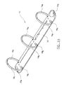
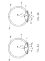
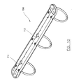
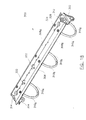
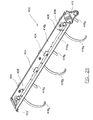
- a ring binder according to a first embodiment of the present invention is generally designated as 10.
- the ring binder 10 includes an upper casing 12 supporting a pair of plates 14 a and 14 b to which three pairs of half-rings 16 a , 16 b and 16 c are mounted.
- the plates 14 a and 14 b are pivotally movable relative to each other, so that the pairs of half-rings 16 a , 16 b and 16 c may be selectively opened (when the angle between the upper surfaces of the plates 14 a and 14 b is more than 180°) or closed (when the angle between the upper surfaces of the plates 14 a and 14 b is less than 180°).
- the half-rings 16 a , 16 b and 16 c extend through three pairs of slots 18 a , 18 b and 18 c on the upper casing 12, which allow the half-rings 16 a , 16 b and 16 c to open or close.
- a hole 20 a and 20 b is a hole 20 a and 20 b , through which a rivet (not shown) may be received to secure the ring binder 10 to an article (not shown), e.g. a paperboard/plastic/metal cover.
- the ring binder 10 includes a lock 22 including a wire 24 with a lock element 26 fixedly crimped thereon.
- the wire 24 includes a shaft 28 which is secured to the middle line of lower surface of the upper casing 12 by three inturned parts 30 crimped therewith.
- the lock 22 is thus supported by the upper casing 12 between the half-rings 16 a and 16 b .
- the lock 22, the wire 24 and the lock element 26 are thus allowed to swivel about the longitudinal axis of the shaft 28.
- the lock 22 is partly received in a channel 29 on the underside of the upper casing 12.
- a corresponding ridge 31 is thus formed on the upper side of the upper casing 12. This arrangement also enhances the strength of the upper casing 12, and thus the ring binder 10.
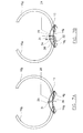
- the half-rings 16 a , 16 b and 16 c may be returned to the closed position by pushing together any one of the three pairs of half-rings 16 a , 16 b and 16 c .
- the plate 14 a will act from above on the bent portion 38 of the wire 24, as shown by an arrow B in Fig. 7B, so that the lock 22 is caused to rotate about the shaft 28 in an anticlockwise direction (according to Fig. 7B) to the position shown in Fig. 6B.
- Fig. 7B As shown in Fig.
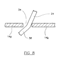
- the bent portion 38 of the wire 24 inclines at an acute angle to the plane containing the plates 14 a and 14 b . There is sufficient space in the aperture 34 for the bent portion 38 to pass through during closing and opening of the half-rings 16 a , 16 b and 16 c .
- the bent portion 38 of the wire 24 may be acutely angled to the longitudinal axis of the ring binder 10. The effectiveness of this action can be still further enhanced by arranging a side of the aperture 34 to be angled to the longitudinal axis of the ring binder 10.
- the extent of return movement of the lock element 26 to its locked position is governed by the tongue 36, which prevents excessive movement of the lock element 26. This also prevents the distal end 32 of the wire 24 from being hidden in the cavity formed by the upper casing 12 and the plates 14 a and 14 b .
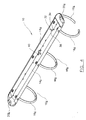
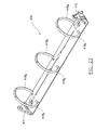
- Figs. 9 to 14 show a second embodiment of a ring binder according to the present invention generally designated as 100.
- the major difference of this embodiment from the first embodiment discussed above is the provision of two lock elements 102 and 104. Consequently, two tongues 106 and 108 are provided on the upper surface of a plate 110 b to govern the movements of the lock elements 102 and 104 back to the locked position, and two openings 112 and 114 are provided on the plate 110 b for allowing part of the lock elements 102 and 104 to pass through.
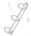
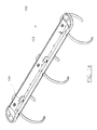
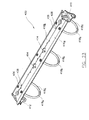
- Figs. 15 and 16 show a third embodiment of a ring binder according to the present invention generally designated as 200.
- the major difference of this embodiment from the first embodiment discussed above is the provision of two securing members 202 at each end of the ring binder 200.
- Each securing member 202 includes six arcuate pointed sectors 204 downwardly depending from the periphery of an orifice 206. It is thus possible to secure the ring binder 200 to a cardboard/paperboard cover without using any rivet.
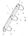
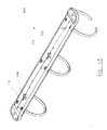
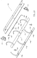
- Figs. 17 to 21 show a fourth embodiment of a ring binder according to the present invention generally designated as 300.
- the ring binder 300 includes two levers 302 and 304, each at one end of the ring binder 300.
- the ring binder 300 also includes an upper casing 306 supporting a pair of plates 308 a and 308 b to which three pairs of half-rings 310 a , 310 b and 310 c are mounted.
- the plates 308 a and 308 b are pivotally movable relative to each other, so that the pairs of half-rings 310 a , 310 b and 310 c may be selectively opened or closed.
- Each of the levers 302 and 304 includes a ledge 312 and 314 respectively. When the levers 302 and 304 are pivoted outwardly, the ledges 312 and 314 act on bottom surfaces of the plates 308a and 308b.
- the ring binder 300 includes a lock 316 including a wire 318 with two lock elements 320 fixedly crimped thereon.
- the lock 316 includes a shaft 322 which is secured to the lower surface of the upper casing 306. The lock 316 is thus supported by the upper casing 306 and may swivel about the longitudinal axis of the shaft 322.
- the ring binder 300 can only be opened by firstly pivoting the lever 302 outward so that the ledge 312 acts on the under surface of the plates 308 a and 308 b .
- the half-rings 310 a and 310 b are then partly opened.
- the plate 308 b will then act upon a bent portion 330 of the wire 318.
- the lock 316 will then be caused to rotate about the shaft 322 to move the lock elements 320 to disengage from the tongues 328 and the plate 308 b to the position as shown in Fig. 20.
- the lock elements 320 are aligned with openings 332, so that the plates 308 a and 308 b can be fully pivoted and the half-rings 310 a , 310 b and 310 c fully opened (as shown in Fig. 21) by subsequently pivoting the lever 304 outward.
- the ring binder 300 can be closed by pushing any of the pairs of half-rings 310 a , 310 b and 310 c together.
- the half-rings 310 a , 310 b and 310 c cannot, however, be opened by first pivoting the lever 304 outward, and subsequently the lever 302.
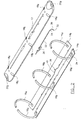
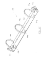
- Figs. 22 to 26 show a fifth embodiment of a ring binder according to the present invention generally designated as 400.
- the ring binder 400 is provided with a lock 402 including two lock members 404 and two distal ends 406. Each of the distal ends 406 of the lock 402, when in the position shown in Fig. 23, extends slightly through an aperture 408.
- either of the levers 410 and 412 may be pivoted outwardly to position as shown in Fig. 25.
- the lock members 404 are aligned with openings 414, thus allowing plates 416 a and 416 b to pivot further, by further outward pivoting movement of the same lever 410 or 412, to open three pairs of half-rings 418 a , 418 b and 418 c to the position as shown in Fig. 26.
- the ring binder 400 cannot be opened by actioning upon any of the pairs of half-rings 418 a , 418 b and 418 c .
Landscapes
- Sheet Holders (AREA)
- Developing Agents For Electrophotography (AREA)
Claims (23)
- Ringbindegerät (10, 100, 200, 300, 400) mit einer im wesentlichen starren oberen Struktur (12, 306), die eine untere Struktur trägt, mit einem Paar Plattenteile (14a, 14b, 110b, 308a, 308b, 416a, 416b), wobei die Plattenteile zwischen einer ersten Position, in der der Winkel zwischen den Oberseiten der Plattenteile kleiner ist als 180°, und einer zweiten Position, in der der Winkel zwischen den Oberseiten der Plattenteile größer ist als 180°, schwenkbar beweglich sind, einem Verriegelungsteil (22, 316, 402), um die untere Struktur zu verriegeln, und Betätigungsmitteln (16a, 302, 304, 410, 412), um das Verriegelungsteil zu betätigen, wobei das Verriegelungsteil an einer ersten Position auf das Ringbindegerät wirkt und das Betätigungsmittel an einer zweiten Position auf das Ringbindegerät wirkt, wobei sich die erste Position in Längsrichtung entfernt von der zweiten Position auf dem Ringbindegerät befindet, wobei das Verriegelungsteil aus einer verriegelten Position, in der es die untere Struktur gegen eine Schwenkbewegung verriegelt, und einer entriegelten Position, in der die untere Struktur schwenkbar beweglich ist, bewegbar ist, dadurch gekennzeichnet, daß das Ringbindegerät eine Betätigungseinrichtung (38, 330) umfaßt, die indirekt durch das Betätigungsmittel bewegbar ist, um das Verriegelungsteil aus der verriegelten Position in die entriegelte Position zu bewegen.
- Ringbindegerät nach Anspruch 1, dadurch gekennzeichnet, daß zumindest zwei Paare von Halbringteilen (16a, 16b, 16c, 310a, 310b, 310c, 418a, 418b, 418c) an der unteren Struktur angebracht sind, wobei sich die erste Position benachbart zu einem ersten Paar der Halbringteile (16b, 310b, 310c, 418b) befindet.
- Ringbindegerät nach Anspruch 2, dadurch gekennzeichnet, daß sich die zweite Position benachbart zu einem zweiten Paar der Halbringteile (16a, 310a, 310c, 418a, 418c) befindet.
- Ringbindegerät nach Anspruch 1, 2 oder 3, dadurch gekennzeichnet, daß das Verriegelungsteil, wenn es sich in der verriegelten Position befindet, mit der Oberseite von einem der Plattenteile (14b, 110b, 308b, 416a) zusammenwirkt.
- Ringbindegerät nach einem der vorangehenden Ansprüche, dadurch gekennzeichnet, daß die Betätigungseinrichtung einen Endabschnitt (32, 324, 406) aufweist, der unter einem spitzen Winkel zur unteren Struktur geneigt ist, wenn sich die Plattenteile in der gleichen Ebene befinden.
- Ringbindegerät nach einem der vorangehenden Ansprüche, dadurch gekennzeichnet, daß ein erstes Plattenteil des Paars Plattenteile (14b, 110b, 308b, 416a) auf eine erste Seite der Betätigungseinrichtung wirkt, um die untere Struktur zu entriegeln.
- Ringbindegerät nach einem der vorangehenden Ansprüche, dadurch gekennzeichnet, daß ein zweites Plattenteil von dem Paar Plattenteile (14a, 110a, 308a, 416b) auf eine zweite Seite der Betätigungseinrichtung wirkt, um die untere Struktur zu verriegeln.
- Ringbindegerät nach Anspruch 5, dadurch gekennzeichnet, daß der Endabschnitt zur Längsachse des Ringbindegeräts spitzwinklig geneigt ist.
- Ringbindegerät nach Anspruch 5 oder 8, dadurch gekennzeichnet, daß die untere Struktur beim Öffnen der Paare von Halbringteilen auf den Endabschnitt wirkt.
- Ringbindegerät nach Anspruch 5, 8 oder 9, dadurch gekennzeichnet, daß die untere Struktur beim Schließen der Paare von Halbringteilen auf den Endabschnitt wirkt.
- Ringbindegerät nach einem der vorangehenden Ansprüche, dadurch gekennzeichnet, daß das Verriegelungsteil fest mit der Betätigungseinrichtung in Eingriff steht.
- Ringbindegerät nach einem der vorangehenden Ansprüche, dadurch gekennzeichnet, daß das Verriegelungsteil zumindest ein Plattenelement (26, 102, 104, 320, 404) aufweist.
- Ringbindegerät nach Anspruch 12, dadurch gekennzeichnet, daß das Verriegelungsteil eine Anzahl von Plattenelementen umfaßt.
- Ringbindegerät nach einem der vorangehenden Ansprüche, dadurch gekennzeichnet, daß das Betätigungsmittel zumindest eines der Paare von Halbringteilen umfaßt.
- Ringbindegerät nach Anspruch 14, dadurch gekennzeichnet, daß sich das Paar von Halbringteilen benachbart zu einem Längsende des Ringbindegeräts befindet.
- Ringbindegerät nach Anspruch 14 oder 15, dadurch gekennzeichnet, daß das Betätigungsmittel eine Anzahl von Paaren von Halbringteilen umfaßt.
- Ringbindegerät nach einem der Ansprüche 14 bis 16, dadurch gekennzeichnet, daß das Betätigungsmittel zwei Paare von Halbringteilen umfaßt, die sich jeweils benachbart zu einem entsprechenden Längsende des Ringbindegeräts befinden.
- Ringbindegerät nach einem der Ansprüche 1 bis 13, dadurch gekennzeichnet, daß das Betätigungsmittel zumindest ein Hebelelement (301, 304, 410, 412) aufweist.
- Ringbindegerät nach Anspruch 18, dadurch gekennzeichnet, daß Betätigungsmittel eine Anzahl von Hebelelementen aufweist.
- Ringbindegerät nach Anspruch 18 oder 19, dadurch gekennzeichnet, daß das Betätigungsmittel zwei Hebelelemente aufweist, die sich an einem jeweiligen Längsende des Ringbindegeräts befinden.
- Ringbindegerät nach einem der Ansprüche 18 bis 20, dadurch gekennzeichnet, daß das Hebelelement schwenkbar beweglich ist, so daß es auf eine Unterseite der unteren Struktur wirkt, um die Betätigungseinrichtung zu bewegen, so daß das Verriegelungsteil von der verriegelten Position in die entriegelte Position bewegt wird.
- Ringbindegerät nach Anspruch 20 oder 21, dadurch gekennzeichnet, daß die untere Struktur von ihrer ersten Position in ihre zweite Position schwenkbar beweglich ist bei Schwenkbewegung von zunächst einem ersten (302) der genannten beiden Hebelelemente und anschließend eines zweiten (304) der beiden Hebelelemente, wobei die untere Struktur gegen eine Schwenkbewegung aus ihrer ersten Position in ihre zweite Position bei einer Schwenkbewegung von zunächst des zweiten (304) der beiden genannten Hebelelemente und anschließend des ersten (302) der beiden Hebelelemente verriegelt ist.
- Ringbindegerät nach Anspruch 20 oder 21, dadurch gekennzeichnet, daß die untere Struktur von ihrer ersten Position in ihre zweite Position schwenkbar beweglich ist bei einer Schwenkbewegung von einem der beiden Hebelelemente (410, 412).
Priority Applications (15)
| Application Number | Priority Date | Filing Date | Title |
|---|---|---|---|
| EP99200935A EP0933233A3 (de) | 1996-05-21 | 1996-07-31 | Ringordner |
| EP96305656A EP0808726B1 (de) | 1996-05-21 | 1996-07-31 | Ringordner |
| EP99200934A EP0933232A3 (de) | 1996-05-21 | 1996-07-31 | Ringordner |
| AU15191/97A AU1519197A (en) | 1996-05-21 | 1997-03-10 | A ring binder |
| NO971127A NO971127D0 (no) | 1996-07-31 | 1997-03-11 | Ringklips |
| CA002199690A CA2199690A1 (en) | 1996-05-21 | 1997-03-11 | Ring binder |
| US08/818,722 US5975785A (en) | 1996-05-21 | 1997-03-14 | Ring binder |
| IDP971452A ID16853A (id) | 1996-05-21 | 1997-05-01 | Pengikat cincin |
| BR9703128A BR9703128A (pt) | 1996-05-21 | 1997-05-12 | Classificador com argolas |
| CN97112409A CN1062218C (zh) | 1996-05-21 | 1997-05-16 | 圆环装订器 |
| PL97320052A PL320052A1 (en) | 1996-05-21 | 1997-05-19 | Snap-ring type nbox file mechanism |
| MXPA/A/1997/003701A MXPA97003701A (en) | 1996-05-21 | 1997-05-20 | An argol folder |
| KR19970019618A KR970074016A (de) | 1996-05-21 | 1997-05-20 | |
| JP9129448A JPH1044668A (ja) | 1996-05-21 | 1997-05-20 | リングバインダー |
| HK98109685.4A HK1008944B (en) | 1996-05-21 | 1998-08-04 | Ring binder |
Applications Claiming Priority (3)
| Application Number | Priority Date | Filing Date | Title |
|---|---|---|---|
| EP96303636 | 1996-05-21 | ||
| EP96303636A EP0808725B1 (de) | 1996-05-21 | 1996-05-21 | Ringordner |
| EP96305656A EP0808726B1 (de) | 1996-05-21 | 1996-07-31 | Ringordner |
Related Child Applications (2)
| Application Number | Title | Priority Date | Filing Date |
|---|---|---|---|
| EP99200934A Division EP0933232A3 (de) | 1996-05-21 | 1996-07-31 | Ringordner |
| EP99200935A Division EP0933233A3 (de) | 1996-05-21 | 1996-07-31 | Ringordner |
Publications (2)
| Publication Number | Publication Date |
|---|---|
| EP0808726A1 EP0808726A1 (de) | 1997-11-26 |
| EP0808726B1 true EP0808726B1 (de) | 2000-04-26 |
Family
ID=26143717
Family Applications (3)
| Application Number | Title | Priority Date | Filing Date |
|---|---|---|---|
| EP99200934A Withdrawn EP0933232A3 (de) | 1996-05-21 | 1996-07-31 | Ringordner |
| EP96305656A Expired - Lifetime EP0808726B1 (de) | 1996-05-21 | 1996-07-31 | Ringordner |
| EP99200935A Withdrawn EP0933233A3 (de) | 1996-05-21 | 1996-07-31 | Ringordner |
Family Applications Before (1)
| Application Number | Title | Priority Date | Filing Date |
|---|---|---|---|
| EP99200934A Withdrawn EP0933232A3 (de) | 1996-05-21 | 1996-07-31 | Ringordner |
Family Applications After (1)
| Application Number | Title | Priority Date | Filing Date |
|---|---|---|---|
| EP99200935A Withdrawn EP0933233A3 (de) | 1996-05-21 | 1996-07-31 | Ringordner |
Country Status (10)
| Country | Link |
|---|---|
| US (1) | US5975785A (de) |
| EP (3) | EP0933232A3 (de) |
| JP (1) | JPH1044668A (de) |
| KR (1) | KR970074016A (de) |
| CN (1) | CN1062218C (de) |
| AU (1) | AU1519197A (de) |
| BR (1) | BR9703128A (de) |
| CA (1) | CA2199690A1 (de) |
| ID (1) | ID16853A (de) |
| PL (1) | PL320052A1 (de) |
Families Citing this family (43)
| Publication number | Priority date | Publication date | Assignee | Title |
|---|---|---|---|---|
| US6293722B1 (en) * | 1999-09-15 | 2001-09-25 | Acco Brands, Inc. | Binder Mechanism |
| AT408535B (de) * | 2000-01-27 | 2001-12-27 | Koloman Handler Ag | Ringmechanik |
| EP1203670A3 (de) * | 2000-11-01 | 2003-08-20 | World Wide Stationery Manufacturing Co. Ltd. | Ringordnermechanik |
| USD468351S1 (en) | 2001-05-11 | 2003-01-07 | World Wide Stationery Manufacturing Company Limited | Ring binder housing cover |
| US7296946B2 (en) | 2001-11-30 | 2007-11-20 | Microsoft Corporation | Ring binder mechanism |
| US7549817B2 (en) | 2002-12-18 | 2009-06-23 | World Wide Stationery Mfg. Co., Ltd. | Ready lock ring binder mechanism |
| US7275886B2 (en) * | 2004-03-15 | 2007-10-02 | World Wide Stationary Mfg. Co., Ltd. | Positive lock ring binder mechanism |
| US7661898B2 (en) | 2004-03-15 | 2010-02-16 | World Wide Stationery Manufacturing Company, Limited | Soft close ring binder mechanism with reinforced travel bar |
| US8573876B2 (en) | 2004-03-15 | 2013-11-05 | World Wide Stationery Manufacturing Company, Limited | Soft close ring binder mechanism with mating ring tips |
| US8002488B2 (en) * | 2004-03-15 | 2011-08-23 | World Wide Stationery Mfg. Co., Ltd. | Soft close ring binder mechanism |
| US7748922B2 (en) * | 2004-03-15 | 2010-07-06 | World Wide Stationery Manufacturing Company, Limited | Ring binder mechanism with dual pivot locking elements |
| US7404685B2 (en) * | 2004-12-30 | 2008-07-29 | World Wide Stationery Manufacturing Company, Limited | Ring binder mechanism spring biased to a locked position when ring members close |
| US20060147254A1 (en) * | 2004-12-30 | 2006-07-06 | World Wide Stationery Mfg. Co., Ltd. | Lever for a ring mechanism |
| US7524128B2 (en) * | 2004-12-30 | 2009-04-28 | World Wide Stationery Manufacturing Company Limited | Ring binder mechanism spring biased to a locked position |
| US7534064B2 (en) * | 2005-01-12 | 2009-05-19 | World Wide Stationery Mfg. Co., Ltd. | Ring mechanism biased to closed and locked position |
| US7726897B2 (en) | 2005-03-22 | 2010-06-01 | World Wide Stationery Mfg. Co., Ltd. | Ring binder mechanism |
| US7661899B2 (en) | 2005-03-22 | 2010-02-16 | World Wide Stationery Mfg. Co., Ltd. | Lever for a ring binder mechanism |
| US7665926B2 (en) * | 2005-05-06 | 2010-02-23 | World Wide Stationery Mfg. Co., Ltd. | Ring mechanism with spring biased travel bar |
| TWD116978S1 (zh) * | 2005-12-02 | 2007-05-11 | 喜利股份有限公司 | 用於檔案夾之裝訂具(二) |
| US7524127B2 (en) | 2005-12-12 | 2009-04-28 | Staples The Office Superstore, Llc | Ring binder mechanism |
| US7527449B2 (en) | 2005-12-12 | 2009-05-05 | Staples The Office Superstore, Llc | Ring binder mechanism |
| US7399136B2 (en) | 2006-01-06 | 2008-07-15 | Staples The Office Superstore Llc | Molded binder |
| USD585935S1 (en) * | 2007-01-05 | 2009-02-03 | World Wide Stationery Mfg. Co., Ltd. | Rectilinear binder ring |
| US10118431B2 (en) * | 2006-07-06 | 2018-11-06 | World Wide Stationery Mfg. Co., Ltd. | Ring for ring binder mechanism |
| US8047737B2 (en) | 2006-09-27 | 2011-11-01 | World Wide Stationery Mfg. Co., Ltd. | Ring binder mechanism |
| US7731441B2 (en) | 2006-09-27 | 2010-06-08 | World Wide Stationery Mfg. Co., Ltd. | Ring binder mechanism |
| US7648302B2 (en) | 2006-09-27 | 2010-01-19 | World Wide Stationery Mfg. Co., Ltd. | Ring binder mechanism |
| US7600939B2 (en) | 2006-09-28 | 2009-10-13 | World Wide Stationery Mfg. Co., Ltd. | Ring binder mechanism with sliding hinge plate |
| US20080175652A1 (en) * | 2007-01-18 | 2008-07-24 | World Wide Stationery Mfg. Co., Ltd. | Ring Binder Mechanism |
| US7654764B2 (en) * | 2007-05-16 | 2010-02-02 | World Wide Stationery Mfg. Co. Ltd. | Ring binder mechanism having blocking device |
| US7819602B2 (en) | 2007-10-31 | 2010-10-26 | World Wide Stationery Mfg. Co., Ltd. | Ring binder mechanism |
| US8147160B2 (en) | 2007-10-31 | 2012-04-03 | World Wide Stationery Mfg. Co., Ltd. | Ring binder mechanism with polymeric housing and actuator |
| US8162556B2 (en) | 2008-12-30 | 2012-04-24 | World Wide Stationery Mfg. Co., Ltd. | Actuator for a ring binder mechanism |
| DE102009005341A1 (de) | 2009-01-16 | 2010-07-22 | Hans Johann Horn | Ordnermechanik |
| CN102126374B (zh) | 2010-01-14 | 2013-10-30 | 国际文具制造厂有限公司 | 具有双时间缓冲的致动器的环形活页夹机构 |
| CA2742462A1 (en) | 2010-06-09 | 2011-12-09 | World Wide Stationery Manufacturing Co., Ltd. | Ring binder mechanism having unitary structure |
| US8517624B2 (en) | 2010-11-12 | 2013-08-27 | R.R. Donnelly & Sons | Binder apparatus |
| US8899866B2 (en) | 2012-04-28 | 2014-12-02 | World Wide Stationary Mfg. Co. Ltd. | Ring binder mechanism with self-locking actuator |
| US10086639B2 (en) | 2013-03-15 | 2018-10-02 | Hans Johann Horn | Binder apparatus |
| US9522561B2 (en) | 2013-08-27 | 2016-12-20 | World Wide Stationery Mfg. Co., Ltd. | Ring binder mechanism |
| US9511617B2 (en) | 2013-10-31 | 2016-12-06 | World Wide Stationary Mfg. Co., Ltd. | Ring binder mechanism |
| CN105984250A (zh) | 2015-02-05 | 2016-10-05 | 国际文具制造厂有限公司 | 具有互锁环形部件的环形装订器 |
| CN106142030A (zh) * | 2015-04-02 | 2016-11-23 | 义乌市映程工艺品有限公司 | 一种刀模收纳册的制作工艺 |
Family Cites Families (7)
| Publication number | Priority date | Publication date | Assignee | Title |
|---|---|---|---|---|
| DE3119779A1 (de) * | 1981-05-19 | 1982-12-09 | Robert Krause Kg, 4992 Espelkamp | Mechanik fuer loseblattbindung |
| US4571108A (en) * | 1982-11-26 | 1986-02-18 | Kurt Vogl | Locking ring binder mechanism with control slide |
| FR2675072B1 (fr) * | 1991-04-15 | 1994-11-25 | Europ Propulsion | Procede de fabrication de butees lamifiees notamment pour articulations de tuyeres de propulseurs. |
| GB2254828B (en) * | 1991-04-15 | 1994-06-22 | Bensons Int Systems | A lockable ring binder mechanism |
| CN1040408C (zh) * | 1991-05-31 | 1998-10-28 | 国际文具制造厂有限公司 | 环式活页纸夹 |
| US5346325A (en) * | 1992-07-24 | 1994-09-13 | Seiichi Yamanoi | Paper holder having a locking device |
| EP0808727B1 (de) * | 1996-05-21 | 2000-10-11 | Leco Stationery Manufacturing Co. Ltd. | Ring-Ordner |
-
1996
- 1996-07-31 EP EP99200934A patent/EP0933232A3/de not_active Withdrawn
- 1996-07-31 EP EP96305656A patent/EP0808726B1/de not_active Expired - Lifetime
- 1996-07-31 EP EP99200935A patent/EP0933233A3/de not_active Withdrawn
-
1997
- 1997-03-10 AU AU15191/97A patent/AU1519197A/en not_active Abandoned
- 1997-03-11 CA CA002199690A patent/CA2199690A1/en not_active Abandoned
- 1997-03-14 US US08/818,722 patent/US5975785A/en not_active Expired - Fee Related
- 1997-05-01 ID IDP971452A patent/ID16853A/id unknown
- 1997-05-12 BR BR9703128A patent/BR9703128A/pt not_active Application Discontinuation
- 1997-05-16 CN CN97112409A patent/CN1062218C/zh not_active Expired - Fee Related
- 1997-05-19 PL PL97320052A patent/PL320052A1/xx unknown
- 1997-05-20 JP JP9129448A patent/JPH1044668A/ja active Pending
- 1997-05-20 KR KR19970019618A patent/KR970074016A/ko not_active Ceased
Also Published As
| Publication number | Publication date |
|---|---|
| MX9703701A (es) | 1998-06-30 |
| EP0933232A3 (de) | 1999-10-27 |
| CA2199690A1 (en) | 1997-11-21 |
| KR970074016A (de) | 1997-12-10 |
| BR9703128A (pt) | 1998-10-27 |
| CN1062218C (zh) | 2001-02-21 |
| CN1172025A (zh) | 1998-02-04 |
| JPH1044668A (ja) | 1998-02-17 |
| ID16853A (id) | 1997-11-13 |
| EP0933232A2 (de) | 1999-08-04 |
| US5975785A (en) | 1999-11-02 |
| EP0808726A1 (de) | 1997-11-26 |
| PL320052A1 (en) | 1997-11-24 |
| EP0933233A2 (de) | 1999-08-04 |
| HK1008944A1 (en) | 1999-05-21 |
| EP0933233A3 (de) | 1999-10-27 |
| AU1519197A (en) | 1997-11-27 |
Similar Documents
| Publication | Publication Date | Title |
|---|---|---|
| EP0808726B1 (de) | Ringordner | |
| EP0808727B1 (de) | Ring-Ordner | |
| US6276862B1 (en) | Binder mechanism | |
| US5354142A (en) | Ring binder | |
| US5067840A (en) | Binder locking ring mechanism with configured trigger | |
| CA2494027C (en) | Soft close ring binder mechanism | |
| US5116157A (en) | Locking ring binder | |
| US5180247A (en) | Ring binder | |
| US7758271B2 (en) | Ring mechanism biased to closed and locked position | |
| CA2594024C (en) | A ring binder mechanism | |
| US5135323A (en) | Ring binder | |
| US5971649A (en) | Ring binder mechanism | |
| GB2231536A (en) | Ring binder locking mechanism | |
| GB2275023A (en) | Ring binder opening mechanism | |
| US6394684B2 (en) | Fastener for a folder | |
| EP0808725B1 (de) | Ringordner | |
| GB2359784A (en) | Ring binder mechanism held shut by inter-engaging teeth | |
| US20080175651A1 (en) | Ring Binder Mechanism with Transverse Actuator | |
| CA2056942C (en) | Ring binder | |
| MXPA97005517A (en) | Argol folder | |
| CA2593611C (en) | Soft close ring binder mechanism | |
| CN200939756Y (zh) | 环形夹机构 | |
| MXPA97003700A (es) | Una carpeta de argollas | |
| MXPA97003701A (en) | An argol folder | |
| CA2272498A1 (en) | A housing for a ring binder mechanism |
Legal Events
| Date | Code | Title | Description |
|---|---|---|---|
| PUAI | Public reference made under article 153(3) epc to a published international application that has entered the european phase |
Free format text: ORIGINAL CODE: 0009012 |
|
| AK | Designated contracting states |
Kind code of ref document: A1 Designated state(s): AT BE CH DE DK ES FI FR GB GR IE IT LI LU MC NL PT SE |
|
| 17P | Request for examination filed |
Effective date: 19980302 |
|
| 17Q | First examination report despatched |
Effective date: 19981209 |
|
| GRAG | Despatch of communication of intention to grant |
Free format text: ORIGINAL CODE: EPIDOS AGRA |
|
| GRAG | Despatch of communication of intention to grant |
Free format text: ORIGINAL CODE: EPIDOS AGRA |
|
| GRAH | Despatch of communication of intention to grant a patent |
Free format text: ORIGINAL CODE: EPIDOS IGRA |
|
| GRAH | Despatch of communication of intention to grant a patent |
Free format text: ORIGINAL CODE: EPIDOS IGRA |
|
| GRAA | (expected) grant |
Free format text: ORIGINAL CODE: 0009210 |
|
| ITF | It: translation for a ep patent filed | ||
| AK | Designated contracting states |
Kind code of ref document: B1 Designated state(s): AT BE CH DE DK ES FI FR GB GR IE IT LI LU MC NL PT SE |
|
| PG25 | Lapsed in a contracting state [announced via postgrant information from national office to epo] |
Ref country code: LI Free format text: LAPSE BECAUSE OF FAILURE TO SUBMIT A TRANSLATION OF THE DESCRIPTION OR TO PAY THE FEE WITHIN THE PRESCRIBED TIME-LIMIT Effective date: 20000426 Ref country code: GR Free format text: LAPSE BECAUSE OF NON-PAYMENT OF DUE FEES Effective date: 20000426 Ref country code: CH Free format text: LAPSE BECAUSE OF FAILURE TO SUBMIT A TRANSLATION OF THE DESCRIPTION OR TO PAY THE FEE WITHIN THE PRESCRIBED TIME-LIMIT Effective date: 20000426 Ref country code: BE Free format text: LAPSE BECAUSE OF FAILURE TO SUBMIT A TRANSLATION OF THE DESCRIPTION OR TO PAY THE FEE WITHIN THE PRESCRIBED TIME-LIMIT Effective date: 20000426 Ref country code: AT Free format text: LAPSE BECAUSE OF FAILURE TO SUBMIT A TRANSLATION OF THE DESCRIPTION OR TO PAY THE FEE WITHIN THE PRESCRIBED TIME-LIMIT Effective date: 20000426 |
|
| REF | Corresponds to: |
Ref document number: 192091 Country of ref document: AT Date of ref document: 20000515 Kind code of ref document: T |
|
| REG | Reference to a national code |
Ref country code: CH Ref legal event code: EP |
|
| ET | Fr: translation filed | ||
| REF | Corresponds to: |
Ref document number: 69607942 Country of ref document: DE Date of ref document: 20000531 |
|
| REG | Reference to a national code |
Ref country code: IE Ref legal event code: FG4D |
|
| REG | Reference to a national code |
Ref country code: ES Ref legal event code: FG2A Ref document number: 2145387 Country of ref document: ES Kind code of ref document: T3 |
|
| PG25 | Lapsed in a contracting state [announced via postgrant information from national office to epo] |
Ref country code: SE Free format text: LAPSE BECAUSE OF FAILURE TO SUBMIT A TRANSLATION OF THE DESCRIPTION OR TO PAY THE FEE WITHIN THE PRESCRIBED TIME-LIMIT Effective date: 20000726 Ref country code: PT Free format text: LAPSE BECAUSE OF FAILURE TO SUBMIT A TRANSLATION OF THE DESCRIPTION OR TO PAY THE FEE WITHIN THE PRESCRIBED TIME-LIMIT Effective date: 20000726 |
|
| PG25 | Lapsed in a contracting state [announced via postgrant information from national office to epo] |
Ref country code: MC Free format text: THE PATENT HAS BEEN ANNULLED BY A DECISION OF A NATIONAL AUTHORITY Effective date: 20000731 Ref country code: LU Free format text: LAPSE BECAUSE OF NON-PAYMENT OF DUE FEES Effective date: 20000731 Ref country code: IE Free format text: LAPSE BECAUSE OF NON-PAYMENT OF DUE FEES Effective date: 20000731 |
|
| REG | Reference to a national code |
Ref country code: DK Ref legal event code: T3 |
|
| REG | Reference to a national code |
Ref country code: CH Ref legal event code: PL |
|
| PLBE | No opposition filed within time limit |
Free format text: ORIGINAL CODE: 0009261 |
|
| STAA | Information on the status of an ep patent application or granted ep patent |
Free format text: STATUS: NO OPPOSITION FILED WITHIN TIME LIMIT |
|
| 26N | No opposition filed | ||
| REG | Reference to a national code |
Ref country code: IE Ref legal event code: MM4A |
|
| PGFP | Annual fee paid to national office [announced via postgrant information from national office to epo] |
Ref country code: FR Payment date: 20010712 Year of fee payment: 6 Ref country code: FI Payment date: 20010712 Year of fee payment: 6 Ref country code: DK Payment date: 20010712 Year of fee payment: 6 |
|
| PGFP | Annual fee paid to national office [announced via postgrant information from national office to epo] |
Ref country code: ES Payment date: 20010719 Year of fee payment: 6 |
|
| PGFP | Annual fee paid to national office [announced via postgrant information from national office to epo] |
Ref country code: DE Payment date: 20010723 Year of fee payment: 6 |
|
| PGFP | Annual fee paid to national office [announced via postgrant information from national office to epo] |
Ref country code: GB Payment date: 20010725 Year of fee payment: 6 |
|
| PGFP | Annual fee paid to national office [announced via postgrant information from national office to epo] |
Ref country code: NL Payment date: 20010730 Year of fee payment: 6 |
|
| REG | Reference to a national code |
Ref country code: GB Ref legal event code: IF02 |
|
| PG25 | Lapsed in a contracting state [announced via postgrant information from national office to epo] |
Ref country code: GB Free format text: LAPSE BECAUSE OF NON-PAYMENT OF DUE FEES Effective date: 20020731 Ref country code: FI Free format text: LAPSE BECAUSE OF NON-PAYMENT OF DUE FEES Effective date: 20020731 Ref country code: DK Free format text: LAPSE BECAUSE OF NON-PAYMENT OF DUE FEES Effective date: 20020731 |
|
| PG25 | Lapsed in a contracting state [announced via postgrant information from national office to epo] |
Ref country code: ES Free format text: LAPSE BECAUSE OF NON-PAYMENT OF DUE FEES Effective date: 20020801 |
|
| PG25 | Lapsed in a contracting state [announced via postgrant information from national office to epo] |
Ref country code: NL Free format text: LAPSE BECAUSE OF NON-PAYMENT OF DUE FEES Effective date: 20030201 Ref country code: DE Free format text: LAPSE BECAUSE OF NON-PAYMENT OF DUE FEES Effective date: 20030201 |
|
| REG | Reference to a national code |
Ref country code: DK Ref legal event code: EBP |
|
| GBPC | Gb: european patent ceased through non-payment of renewal fee |
Effective date: 20020731 |
|
| PG25 | Lapsed in a contracting state [announced via postgrant information from national office to epo] |
Ref country code: FR Free format text: LAPSE BECAUSE OF NON-PAYMENT OF DUE FEES Effective date: 20030331 |
|
| NLV4 | Nl: lapsed or anulled due to non-payment of the annual fee |
Effective date: 20030201 |
|
| REG | Reference to a national code |
Ref country code: FR Ref legal event code: ST |
|
| REG | Reference to a national code |
Ref country code: ES Ref legal event code: FD2A Effective date: 20030811 |
|
| PG25 | Lapsed in a contracting state [announced via postgrant information from national office to epo] |
Ref country code: IT Free format text: LAPSE BECAUSE OF NON-PAYMENT OF DUE FEES;WARNING: LAPSES OF ITALIAN PATENTS WITH EFFECTIVE DATE BEFORE 2007 MAY HAVE OCCURRED AT ANY TIME BEFORE 2007. THE CORRECT EFFECTIVE DATE MAY BE DIFFERENT FROM THE ONE RECORDED. Effective date: 20050731 |