EP0808515B1 - Vorrichtung zur frequenzfilterung - Google Patents
Vorrichtung zur frequenzfilterung Download PDFInfo
- Publication number
- EP0808515B1 EP0808515B1 EP96941062A EP96941062A EP0808515B1 EP 0808515 B1 EP0808515 B1 EP 0808515B1 EP 96941062 A EP96941062 A EP 96941062A EP 96941062 A EP96941062 A EP 96941062A EP 0808515 B1 EP0808515 B1 EP 0808515B1
- Authority
- EP
- European Patent Office
- Prior art keywords
- adjusting
- conductor
- outer pipe
- adjusting means
- adjusting element
- Prior art date
- Legal status (The legal status is an assumption and is not a legal conclusion. Google has not performed a legal analysis and makes no representation as to the accuracy of the status listed.)
- Expired - Lifetime
Links
- 238000001914 filtration Methods 0.000 title claims description 3
- 239000004020 conductor Substances 0.000 claims abstract description 25
- 239000000463 material Substances 0.000 claims abstract description 13
- 241000446313 Lamella Species 0.000 claims description 25
- 239000011248 coating agent Substances 0.000 claims description 5
- 238000000576 coating method Methods 0.000 claims description 5
- 230000004323 axial length Effects 0.000 abstract description 2
- RYGMFSIKBFXOCR-UHFFFAOYSA-N Copper Chemical compound [Cu] RYGMFSIKBFXOCR-UHFFFAOYSA-N 0.000 description 2
- 229910052802 copper Inorganic materials 0.000 description 2
- 239000010949 copper Substances 0.000 description 2
- 239000000203 mixture Substances 0.000 description 2
- 229910016347 CuSn Inorganic materials 0.000 description 1
- 229910002531 CuTe Inorganic materials 0.000 description 1
- 229910001374 Invar Inorganic materials 0.000 description 1
- 238000005452 bending Methods 0.000 description 1
- 238000004519 manufacturing process Methods 0.000 description 1
- 238000000034 method Methods 0.000 description 1
Images
Classifications
-
- H—ELECTRICITY
- H01—ELECTRIC ELEMENTS
- H01P—WAVEGUIDES; RESONATORS, LINES, OR OTHER DEVICES OF THE WAVEGUIDE TYPE
- H01P7/00—Resonators of the waveguide type
- H01P7/04—Coaxial resonators
Definitions
- the present invention relates to a device for filtering frequency, which device comprises a shell and a conductor adjustable in length, which conductor comprises an outer pipe affixed at its first end to the shell and an extruding adjusting element adjustable in the direction of the central axis of the outer pipe at the second, free end of the outer pipe by means of adjusting means for adjusting the length of the conductor, which adjusting element is of a flexible surface material and affixed at its first end to the outer pipe and at its other end to the adjusting means and which adjusting element forms the free end of the conductor.
- the filter according to Finnish Patent Application 944,806 not public at the filing of the present application and published as WO 96/12321, comprises an outer pipe attached to the filter shell, adjusting means adapted coaxially inside the outer pipe and adjusting elements adapted between the outer pipe and the end of the adjusting means.
- the adjusting elements comprise a laminated or film structure bent and attached between the outer pipe and the end of the adjusting means.
- the laminated or film structure comprises several separate, adjoining lamellas or films essentially bent into a U shape and attached to one another into an annular structure and the laminated or film structure is attached to the outer pipe and the adjusting means with annular retainers whose periphery has mounting slots for said structure.
- the mounting of the adjusting element has thus been rather difficult and complicated.
- the end of the adjusting film protruding from the outer pipe has not been in the same line as the outer pipe but the adjusting element has protruded essentially perpendicularly away from the line of the outer pipe.
- the object is that the length of the conductor, that is, the length in the direction of the free end of the outer pipe, could be adjusted. If the filter, for example, is also adjusted so that the part of the adjusting element bending most forms as small an angle as possible, such a great stress is directed to the adjusting element that in the worst case it may get damaged.
- the object of the present invention is to eliminate the disadvantages described above and improve the device. This object is achieved with the solution according to the invention which is characterized by what is disclosed in the characterizing part of claim 1.
- the idea of the invention is that the second end of the adjusting element which is attached to the adjusting means is situated closer to the fixture of the outer pipe than the free end of the conductor. This structure provides the advantage that frequency adjustment will be considerably more accurate than in prior art solutions.
- the solution of the invention will make the adjustment accuracy of frequency of the filter significantly better than in prior art solutions.
- the frequency change of the filter corresponding to the travel of one millimetre of the adjusting means is only 1.6 MHz, whereas previously the frequency change has been as much as 2.6 MHz.
- the more accurate frequency adjustment of the invention is based on that the travel of the adjusting element will be half of that in the prior art solution.
- This essential improvement in frequency adjustment means that frequency can be easily adjusted just manually to be correct. If frequency adjustment is automatic, that is, a stepping motor moves the adjusting means, the stepping motor requires only a smaller accuracy for attaining the same accuracy as in the prior art solution.
- the adjusting element adjustable by means of the adjusting means for adjusting the length of the conductor is attached to the adjusting means and the outer pipe in such a manner that the adjusting element forms the free end of the conductor with all the travel values of the adjusting means. In this way, the whole adjusting range will be adjusted accurately.
- the adjusting element comprises plate strips, that is, lamellas attached to the adjusting means.
- the lamellas are bent advantageously into such a U shape that frequency adjustment is almost frictionless and the lamellas form the free end of the conductor.
- the lamellas are attached to the adjusting means radially, which provides good directional stability for the lamellas. Directional stability of the lamellas can be further improved if the lamellas have a curved shape in the lateral direction.
- the lamellas may be manufactured of a material with good electroconductivity or they can possibly be manufactured of plastic or any such material, which will make the filter lighter and more economic to manufacture. If the lamellas are produced of plastic or any such material, the lamellas have to be coated with a coating with good electroconductivity, whereby electroconductivity will improve and the lamellas will become a part of a conductor adjustable in length.
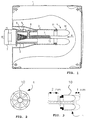
- Figure 1 shows a device according to the invention which in this exemplary case is automatically adjustable, comprising an outer pipe 2, preferably of copper, attached inside a shell 1, adjusting means 3, preferably of invar, adapted coaxially inside the outer pipe and a flexible adjusting element 4.
- the adjusting element 4 is attached at its first end to the outer pipe 2, and at its second end to the adjusting means 3 and it is preferably of a coated surface material and the axial length of the adjusting element 4 from the free end of the outer pipe 2 is adjustable by the adjusting means 3.
- the filter also comprises a stepping motor 7 moving the adjusting means 3 and adapted into an extension 5 of the outer pipe 2 outside the shell 1 by means of a mounting pipe 6.
- a suitably dimensioned mounting pipe works here simultaneously as a temperature compensation pipe that compensates for the changes in length caused by temperature changes in the assembly of the outer pipe 2, the adjusting means 3, the adjusting element 4 and the steps of the stepping motor 7.
- An anti-rotation pin of the adjusting means 3 is indicated by numeral 8 and a limit switch of the motor 7 by numeral 9.
- the limit switch 9 halts the stepping motor 7 when the adjusting means 3 cannot adjust the length of the conductor any more.
- the adjusting element 4 comprises lamellas 10 which form the free end of the conductor.
- the lamellas are affixed at their first end to the outer pipe 2 with a first retaining element 11 and at their other end to the adjusting means 3 with a second retaining element 12 which is preferably a screw.
- Figure 2 shows that the several separate lamellas 10 of the adjusting element 4 bent essentially into a U shape are connected into a radial structure around the adjusting means 3.
- the adjusting means 3 are adapted into the lamellas 10 of the adjusting element 4 bent into a U shape in such a manner that it is possible to adjust the length of the conductor by the adjusting means 3 by adjusting the length of the lamellas 10 of the adjusting element 4.
- the frequency to be adjusted varies as well. Because of the structure of the adjusting element 4, the force required for frequency adjustment will remain small, that is, the filter is light to adjust.
- Figure 3 shows a cross sectional view of the adjusting element 4 where two lamellas 10 are attached at their first end to the outer pipe 2 and at their second end to the adjusting means 3.
- the lamellas 10 form a free end of the conductor which is essentially U shaped.
- the travel of the adjusting means 3 is two millimetres, whereas the travel of the adjusting element 4 is only one millimetre.
- This means that frequency adjustment of the filter has such a structure that the travel of the free end of the conductor determining the frequency of the filter is only half of the distance travelled by the adjusting means 3. In practice, this means that by means of the solution of the invention, it is very easy to have the filter tuned accurately onto the required frequency.
Landscapes
- Control Of Motors That Do Not Use Commutators (AREA)
- Filters And Equalizers (AREA)
- Transplanting Machines (AREA)
- Networks Using Active Elements (AREA)
- Measurement And Recording Of Electrical Phenomena And Electrical Characteristics Of The Living Body (AREA)
- Electrotherapy Devices (AREA)
- Filtering Of Dispersed Particles In Gases (AREA)
- Surface Acoustic Wave Elements And Circuit Networks Thereof (AREA)
Claims (8)
- Vorrichtung zur Frequenzfilterung, wobei die Vorrichtung ein Gehäuse (1) und einen in der Länge einstellbaren Leiter umfasst, wobei der Leiter ein äußeres Rohr (2), das an einem zugehörigen ersten Ende bei dem Gehäuse (1) befestigt ist, und ein hervorstehendes Einstellelement (4) umfasst, das in der Richtung der Mittelachse des äußeren Rohrs bei dem zweiten, freien Ende des äußeren Rohrs mittels einer Einstelleinrichtung (3) zur Einstellung der Länge des Leiters einstellbar ist, wobei das Einstellelement aus einem flexiblen Oberflächenmaterial hergestellt ist und an einem zugehörigen ersten Ende bei dem zweiten Ende des äußeren Rohrs (2) sowie an dem zugehörigen zweiten Ende bei der Einstelleinrichtung (3) befestigt ist und das Einstellelement (4) sich in dem freien Ende des Leiters befindet, dadurch gekennzeichnet, dass sich das zweite Ende des Einstellelements (4), das bei der Einstelleinrichtung (3) befestigt ist, näher bei der Befestigung des äußeren Rohrs (2) als bei dem freien Ende des Leiters befindet.
- Vorrichtung nach Anspruch 1, dadurch gekennzeichnet, dass das freie Ende des Leiters im Wesentlichen eine derartige U-Form aufweist, dass die U-Form axial um die Einstelleinrichtung (3) gedreht ist.
- Vorrichtung nach Anspruch 1, dadurch gekennzeichnet, dass das Einstellelement (4) Lamellen (10) aufweist.
- Vorrichtung nach Anspruch 3, dadurch gekennzeichnet, dass die Lamellen (10) radial bei der Einstelleinrichtung (3) angebracht sind.
- Vorrichtung nach Anspruch 3, dadurch gekennzeichnet, dass die Lamellen (10) aus Kunststoff oder einem anderen derartigen Material hergestellt sind.
- Vorrichtung nach Anspruch 3, dadurch gekennzeichnet, dass die Lamellen (10) eine gebogene Form in der lateralen Richtung aufweisen.
- Vorrichtung nach Anspruch 5, dadurch gekennzeichnet, dass Kunststoff oder ein anderes derartiges Oberflächenmaterial eine Ummantelung umfassen.
- Vorrichtung nach Anspruch 7, dadurch gekennzeichnet, dass die Ummantelung aus einem Material mit guter elektrischer Leitfähigkeit hergestellt ist.
Applications Claiming Priority (3)
| Application Number | Priority Date | Filing Date | Title |
|---|---|---|---|
| FI955918 | 1995-12-08 | ||
| FI955918A FI99218C (fi) | 1995-12-08 | 1995-12-08 | Laite taajuuden suodattamiseksi |
| PCT/FI1996/000645 WO1997022157A1 (en) | 1995-12-08 | 1996-12-03 | Device for filtering frequency |
Publications (2)
| Publication Number | Publication Date |
|---|---|
| EP0808515A1 EP0808515A1 (de) | 1997-11-26 |
| EP0808515B1 true EP0808515B1 (de) | 2002-04-03 |
Family
ID=8544510
Family Applications (1)
| Application Number | Title | Priority Date | Filing Date |
|---|---|---|---|
| EP96941062A Expired - Lifetime EP0808515B1 (de) | 1995-12-08 | 1996-12-03 | Vorrichtung zur frequenzfilterung |
Country Status (10)
| Country | Link |
|---|---|
| US (1) | US5850169A (de) |
| EP (1) | EP0808515B1 (de) |
| JP (1) | JPH11502090A (de) |
| CN (1) | CN1172554A (de) |
| AT (1) | ATE215748T1 (de) |
| AU (1) | AU715494B2 (de) |
| DE (1) | DE69620392T2 (de) |
| FI (1) | FI99218C (de) |
| NO (1) | NO973540D0 (de) |
| WO (1) | WO1997022157A1 (de) |
Families Citing this family (4)
| Publication number | Priority date | Publication date | Assignee | Title |
|---|---|---|---|---|
| FI104591B (fi) * | 1998-02-04 | 2000-02-29 | Adc Solitra Oy | Suodatin ja suodattimen valmistusmenetelmä sekä suodattimen kotelorakenteen osa |
| US6407651B1 (en) | 1999-12-06 | 2002-06-18 | Kathrein, Inc., Scala Division | Temperature compensated tunable resonant cavity |
| FI119207B (fi) | 2003-03-18 | 2008-08-29 | Filtronic Comtek Oy | Koaksiaaliresonaattorisuodatin |
| US20060135092A1 (en) * | 2004-12-16 | 2006-06-22 | Kathrein Austria Ges. M. B. H. | Radio frequency filter |
Family Cites Families (6)
| Publication number | Priority date | Publication date | Assignee | Title |
|---|---|---|---|---|
| US2742617A (en) * | 1952-08-11 | 1956-04-17 | Gen Electric | Tunable cavity resonator |
| AU3500078A (en) * | 1977-04-21 | 1979-10-18 | Del Technology Ltd | Coaxial resonator tuning |
| US4521754A (en) * | 1983-08-29 | 1985-06-04 | International Telephone And Telegraph Corporation | Tuning and temperature compensation arrangement for microwave resonators |
| FI94683C (fi) * | 1993-10-20 | 1995-10-10 | Nokia Telecommunications Oy | Lämpötilakompensoitu kompaineri |
| FI96151C (fi) * | 1994-10-12 | 1996-05-10 | Nokia Telecommunications Oy | Kompaineri |
| US5612655A (en) * | 1995-07-06 | 1997-03-18 | Allen Telecom Group, Inc. | Filter assembly comprising a plastic resonator support and resonator tuning assembly |
-
1995
- 1995-12-08 FI FI955918A patent/FI99218C/fi active IP Right Grant
-
1996
- 1996-12-03 JP JP9519970A patent/JPH11502090A/ja active Pending
- 1996-12-03 AU AU10334/97A patent/AU715494B2/en not_active Ceased
- 1996-12-03 EP EP96941062A patent/EP0808515B1/de not_active Expired - Lifetime
- 1996-12-03 US US08/875,199 patent/US5850169A/en not_active Expired - Fee Related
- 1996-12-03 WO PCT/FI1996/000645 patent/WO1997022157A1/en not_active Ceased
- 1996-12-03 AT AT96941062T patent/ATE215748T1/de not_active IP Right Cessation
- 1996-12-03 CN CN96191762A patent/CN1172554A/zh active Pending
- 1996-12-03 DE DE69620392T patent/DE69620392T2/de not_active Expired - Fee Related
-
1997
- 1997-08-01 NO NO973540A patent/NO973540D0/no not_active Application Discontinuation
Also Published As
| Publication number | Publication date |
|---|---|
| WO1997022157A1 (en) | 1997-06-19 |
| AU1033497A (en) | 1997-07-03 |
| JPH11502090A (ja) | 1999-02-16 |
| DE69620392T2 (de) | 2002-10-17 |
| CN1172554A (zh) | 1998-02-04 |
| FI99218B (fi) | 1997-07-15 |
| AU715494B2 (en) | 2000-02-03 |
| FI955918A0 (fi) | 1995-12-08 |
| EP0808515A1 (de) | 1997-11-26 |
| US5850169A (en) | 1998-12-15 |
| NO973540L (no) | 1997-08-01 |
| FI99218C (fi) | 1997-10-27 |
| DE69620392D1 (de) | 2002-05-08 |
| NO973540D0 (no) | 1997-08-01 |
| ATE215748T1 (de) | 2002-04-15 |
Similar Documents
| Publication | Publication Date | Title |
|---|---|---|
| US3931629A (en) | Control element for displacing components of optical systems | |
| KR20040004366A (ko) | 셀 기지국 안테나 | |
| EP0808515B1 (de) | Vorrichtung zur frequenzfilterung | |
| ATE305661T1 (de) | Sende-empfangssatellitenantenne mit hoher leistung und niedrigem kostenaufwand | |
| WO2021171157A1 (en) | Prism for repointing reflector antenna main beam | |
| CN1434586A (zh) | 螺旋型初级发射器和配备它的变换器 | |
| CA1081353A (en) | Method of adjusting an optical element of a gas discharge laser | |
| EP0458620A2 (de) | Mikrowellenantennen | |
| JPS6223289B2 (de) | ||
| US4577944A (en) | Lens mount with noise reducing means | |
| US5736912A (en) | Dielectric resonator frequency adjusting mechanism with a resin layer | |
| EP0830527B1 (de) | Stellantrieb für lineare bewegung | |
| JPH09507006A (ja) | 温度補償型コンバイナ | |
| JPH0996850A (ja) | 絞り部材およびレンズ鏡筒 | |
| US6097348A (en) | Compact waveguide horn antenna and method of manufacture | |
| US6359533B1 (en) | Combline filter and method of use thereof | |
| EP1111709A1 (de) | Verfahren zur Herstellung des Innenleiters eines Hohlraumresonators und Innenleiter eines Hohlraumresonators | |
| JPS6121851Y2 (de) | ||
| CA2268425A1 (en) | Fibre bragg grating with offset equivalent mirror plane and method for its manufacture | |
| US20190326657A1 (en) | Method of making a rod antenna | |
| JPS6143287Y2 (de) | ||
| US5754907A (en) | Diaphragm movement device | |
| KR100267245B1 (ko) | 셔틀방식스캐너의렌즈위치조정장치 | |
| WO1996012321A1 (en) | Combiner | |
| EP0806807B1 (de) | Koaxialer Filter |
Legal Events
| Date | Code | Title | Description |
|---|---|---|---|
| PUAI | Public reference made under article 153(3) epc to a published international application that has entered the european phase |
Free format text: ORIGINAL CODE: 0009012 |
|
| 17P | Request for examination filed |
Effective date: 19970808 |
|
| AK | Designated contracting states |
Kind code of ref document: A1 Designated state(s): AT BE CH DE DK ES FI FR GB GR IE IT LI LU MC NL PT SE |
|
| RAP1 | Party data changed (applicant data changed or rights of an application transferred) |
Owner name: NOKIA NETWORKS OY |
|
| 17Q | First examination report despatched |
Effective date: 20000809 |
|
| GRAG | Despatch of communication of intention to grant |
Free format text: ORIGINAL CODE: EPIDOS AGRA |
|
| GRAG | Despatch of communication of intention to grant |
Free format text: ORIGINAL CODE: EPIDOS AGRA |
|
| GRAH | Despatch of communication of intention to grant a patent |
Free format text: ORIGINAL CODE: EPIDOS IGRA |
|
| GRAH | Despatch of communication of intention to grant a patent |
Free format text: ORIGINAL CODE: EPIDOS IGRA |
|
| REG | Reference to a national code |
Ref country code: GB Ref legal event code: IF02 |
|
| GRAA | (expected) grant |
Free format text: ORIGINAL CODE: 0009210 |
|
| RAP1 | Party data changed (applicant data changed or rights of an application transferred) |
Owner name: NOKIA CORPORATION |
|
| AK | Designated contracting states |
Kind code of ref document: B1 Designated state(s): AT BE CH DE DK ES FI FR GB GR IE IT LI LU MC NL PT SE |
|
| PG25 | Lapsed in a contracting state [announced via postgrant information from national office to epo] |
Ref country code: NL Free format text: LAPSE BECAUSE OF FAILURE TO SUBMIT A TRANSLATION OF THE DESCRIPTION OR TO PAY THE FEE WITHIN THE PRESCRIBED TIME-LIMIT Effective date: 20020403 Ref country code: LI Free format text: LAPSE BECAUSE OF FAILURE TO SUBMIT A TRANSLATION OF THE DESCRIPTION OR TO PAY THE FEE WITHIN THE PRESCRIBED TIME-LIMIT Effective date: 20020403 Ref country code: GR Free format text: LAPSE BECAUSE OF FAILURE TO SUBMIT A TRANSLATION OF THE DESCRIPTION OR TO PAY THE FEE WITHIN THE PRESCRIBED TIME-LIMIT Effective date: 20020403 Ref country code: FI Free format text: LAPSE BECAUSE OF FAILURE TO SUBMIT A TRANSLATION OF THE DESCRIPTION OR TO PAY THE FEE WITHIN THE PRESCRIBED TIME-LIMIT Effective date: 20020403 Ref country code: CH Free format text: LAPSE BECAUSE OF FAILURE TO SUBMIT A TRANSLATION OF THE DESCRIPTION OR TO PAY THE FEE WITHIN THE PRESCRIBED TIME-LIMIT Effective date: 20020403 Ref country code: BE Free format text: LAPSE BECAUSE OF FAILURE TO SUBMIT A TRANSLATION OF THE DESCRIPTION OR TO PAY THE FEE WITHIN THE PRESCRIBED TIME-LIMIT Effective date: 20020403 Ref country code: AT Free format text: LAPSE BECAUSE OF FAILURE TO SUBMIT A TRANSLATION OF THE DESCRIPTION OR TO PAY THE FEE WITHIN THE PRESCRIBED TIME-LIMIT Effective date: 20020403 |
|
| REF | Corresponds to: |
Ref document number: 215748 Country of ref document: AT Date of ref document: 20020415 Kind code of ref document: T |
|
| REG | Reference to a national code |
Ref country code: CH Ref legal event code: EP |
|
| REF | Corresponds to: |
Ref document number: 69620392 Country of ref document: DE Date of ref document: 20020508 |
|
| REG | Reference to a national code |
Ref country code: IE Ref legal event code: FG4D |
|
| PG25 | Lapsed in a contracting state [announced via postgrant information from national office to epo] |
Ref country code: SE Free format text: LAPSE BECAUSE OF FAILURE TO SUBMIT A TRANSLATION OF THE DESCRIPTION OR TO PAY THE FEE WITHIN THE PRESCRIBED TIME-LIMIT Effective date: 20020703 Ref country code: PT Free format text: LAPSE BECAUSE OF FAILURE TO SUBMIT A TRANSLATION OF THE DESCRIPTION OR TO PAY THE FEE WITHIN THE PRESCRIBED TIME-LIMIT Effective date: 20020703 Ref country code: DK Free format text: LAPSE BECAUSE OF FAILURE TO SUBMIT A TRANSLATION OF THE DESCRIPTION OR TO PAY THE FEE WITHIN THE PRESCRIBED TIME-LIMIT Effective date: 20020703 |
|
| ET | Fr: translation filed | ||
| NLV1 | Nl: lapsed or annulled due to failure to fulfill the requirements of art. 29p and 29m of the patents act | ||
| REG | Reference to a national code |
Ref country code: CH Ref legal event code: PL |
|
| PG25 | Lapsed in a contracting state [announced via postgrant information from national office to epo] |
Ref country code: ES Free format text: LAPSE BECAUSE OF FAILURE TO SUBMIT A TRANSLATION OF THE DESCRIPTION OR TO PAY THE FEE WITHIN THE PRESCRIBED TIME-LIMIT Effective date: 20021030 |
|
| PG25 | Lapsed in a contracting state [announced via postgrant information from national office to epo] |
Ref country code: LU Free format text: LAPSE BECAUSE OF NON-PAYMENT OF DUE FEES Effective date: 20021203 Ref country code: IE Free format text: LAPSE BECAUSE OF NON-PAYMENT OF DUE FEES Effective date: 20021203 |
|
| PLBE | No opposition filed within time limit |
Free format text: ORIGINAL CODE: 0009261 |
|
| STAA | Information on the status of an ep patent application or granted ep patent |
Free format text: STATUS: NO OPPOSITION FILED WITHIN TIME LIMIT |
|
| 26N | No opposition filed |
Effective date: 20030106 |
|
| PG25 | Lapsed in a contracting state [announced via postgrant information from national office to epo] |
Ref country code: MC Free format text: LAPSE BECAUSE OF NON-PAYMENT OF DUE FEES Effective date: 20030701 |
|
| REG | Reference to a national code |
Ref country code: IE Ref legal event code: MM4A |
|
| PGFP | Annual fee paid to national office [announced via postgrant information from national office to epo] |
Ref country code: GB Payment date: 20051130 Year of fee payment: 10 |
|
| PGFP | Annual fee paid to national office [announced via postgrant information from national office to epo] |
Ref country code: DE Payment date: 20051201 Year of fee payment: 10 |
|
| PGFP | Annual fee paid to national office [announced via postgrant information from national office to epo] |
Ref country code: FR Payment date: 20051208 Year of fee payment: 10 |
|
| PGFP | Annual fee paid to national office [announced via postgrant information from national office to epo] |
Ref country code: IT Payment date: 20061231 Year of fee payment: 11 |
|
| PG25 | Lapsed in a contracting state [announced via postgrant information from national office to epo] |
Ref country code: DE Free format text: LAPSE BECAUSE OF NON-PAYMENT OF DUE FEES Effective date: 20070703 |
|
| GBPC | Gb: european patent ceased through non-payment of renewal fee |
Effective date: 20061203 |
|
| REG | Reference to a national code |
Ref country code: FR Ref legal event code: ST Effective date: 20070831 |
|
| PG25 | Lapsed in a contracting state [announced via postgrant information from national office to epo] |
Ref country code: GB Free format text: LAPSE BECAUSE OF NON-PAYMENT OF DUE FEES Effective date: 20061203 |
|
| PG25 | Lapsed in a contracting state [announced via postgrant information from national office to epo] |
Ref country code: FR Free format text: LAPSE BECAUSE OF NON-PAYMENT OF DUE FEES Effective date: 20070102 |
|
| PG25 | Lapsed in a contracting state [announced via postgrant information from national office to epo] |
Ref country code: IT Free format text: LAPSE BECAUSE OF NON-PAYMENT OF DUE FEES Effective date: 20071203 |