EP0808466B1 - Verfahren zur herstellung von einer akustischen linienanordnung - Google Patents
Verfahren zur herstellung von einer akustischen linienanordnung Download PDFInfo
- Publication number
- EP0808466B1 EP0808466B1 EP96901873A EP96901873A EP0808466B1 EP 0808466 B1 EP0808466 B1 EP 0808466B1 EP 96901873 A EP96901873 A EP 96901873A EP 96901873 A EP96901873 A EP 96901873A EP 0808466 B1 EP0808466 B1 EP 0808466B1
- Authority
- EP
- European Patent Office
- Prior art keywords
- layer
- foam
- cylinders
- net
- cylinder
- Prior art date
- Legal status (The legal status is an assumption and is not a legal conclusion. Google has not performed a legal analysis and makes no representation as to the accuracy of the status listed.)
- Expired - Lifetime
Links
Images

Classifications
-
- G—PHYSICS
- G01—MEASURING; TESTING
- G01V—GEOPHYSICS; GRAVITATIONAL MEASUREMENTS; DETECTING MASSES OR OBJECTS; TAGS
- G01V1/00—Seismology; Seismic or acoustic prospecting or detecting
- G01V1/16—Receiving elements for seismic signals; Arrangements or adaptations of receiving elements
- G01V1/20—Arrangements of receiving elements, e.g. geophone pattern
- G01V1/201—Constructional details of seismic cables, e.g. streamers
-
- Y—GENERAL TAGGING OF NEW TECHNOLOGICAL DEVELOPMENTS; GENERAL TAGGING OF CROSS-SECTIONAL TECHNOLOGIES SPANNING OVER SEVERAL SECTIONS OF THE IPC; TECHNICAL SUBJECTS COVERED BY FORMER USPC CROSS-REFERENCE ART COLLECTIONS [XRACs] AND DIGESTS
- Y10—TECHNICAL SUBJECTS COVERED BY FORMER USPC
- Y10T—TECHNICAL SUBJECTS COVERED BY FORMER US CLASSIFICATION
- Y10T156/00—Adhesive bonding and miscellaneous chemical manufacture
- Y10T156/10—Methods of surface bonding and/or assembly therefor
- Y10T156/1052—Methods of surface bonding and/or assembly therefor with cutting, punching, tearing or severing
- Y10T156/1062—Prior to assembly
Definitions
- the present invention relates to methods which allow manufacture a linear acoustic antenna of the type intended to be towed behind a boat for explorations acoustic, for example oil research.
- Such antennas are formed of sections, preferably identical, connected to each other by connectors. These sections are generally formed by a sheath containing the hydrophones of reception and various electronic devices. Electric cables run from one end to the other of the section to allow supplying these organs and bring back to the ship the signals received by the hydrophones. To further obtain sufficient tensile strength, force recovery cables are used which connect the connectors of the two extremities and which make it possible not to apply the tensile forces to the sheath, nor on the electrical connection cables.
- the second spiral layer is made of non-woven material.
- the second spiral layer is made with a polyester film.
- the foam cylinder is produced from a foam tube into which foam cylinders are inserted adapted to the inside diameter of this tube.
- rings are used instead of radial reinforcement a continuous helical strip wound or extruded on the foam cylinders.
- the structure of the antenna manufactured according to the method according to the invention is derived from that described, at least partially, in the European patent EP-A-0 508 904. To avoid tension on the signaling cable, see European patent EP-A-0 560 674.
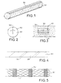
- a first step we made in a known manner, for example by molding or by cutting into a block, open cell foam cylinders of a such a length, for example one meter, that these cylinders are easily manipulable. On these cylinders we stick at least three strips inextensible fabric 102, distributed evenly over the circumference.
- a third step shown in Figure 3, we dig inside the cylinder of the axial cavities 104, using for this the opening obtained by folding down on each side according to the arrows shown in Figure 2 the two half-parts of the cylinder determined through slot 103.
- These acoustic modules include for example a hydrophone and a preamplifier. They have end lugs 106 which allow immobilize them in the cavity 104 along the axis of the foam cylinder. They also include connection wires 107, which we just made go through slot 103.
- the foam cylinder is closed in trapping the electroacoustic modules 105 in the cells 104 and leaving the connection wires 107 outside the cylinder. cylinder being thus closed, it is glued with dots of glue which keep in this position.
- a fifth step shown in Figure 4, we put end to end the set of cylinders intended to form a single section of the antenna, and a first layer of a material is wound on this assembly non-woven 109 forming a band whose successive turns come cover fairly widely at the level represented by the oblique lines dotted 110.
- This nonwoven material is porous to allow impregnation subsequent foam. Then manually extract the connection wires so that these are not masked by the layer of nonwoven material.
- a sixth step (, we set up around the structure thus obtained the layer of wires used to connect the modules 105 in winding this sheet in the form of one or more crossed layers.
- a seventh step we coil in a spiral, but this time without covering, a second layer of porous nonwoven material to maintain the layer of wires that we put in place during the sixth step.
- a film could be used, preferably in polyester, instead of the nonwoven material. In both cases, we localize visually connecting wires through the layer thus put in place.
- the modules are wired electroacoustics.
- connection wires being extracted, they are connected to the cables of the tablecloth set up during the sixth step, using to locate the color codes carried by the different threads. Alternatively, we could use bar codes.
- the wiring is thus carried out, in a ninth step we spool a third layer of porous nonwoven material, this time with overlapping of the turns on each other.
- reinforcement rings 112 made of a very resistant, for example of the epoxy carbon fiber type. These rings are from preferably placed in front of the 105 electroacoustic modules and they are held in place by bonding to the net 111.
- this fourth layer we put on top of this fourth layer another net formed of broad mesh strands, preferably polyester.
- a fourteenth step the sheath intended for protect the assembly on the surface of the fourth layer of nonwoven, in filling it at the same time, according to a known technique, with fibers resistant, made for example with a material such as KEVLAR (trademark).
- This extrusion is done conventionally using an extruder with a square head in which you can do penetrate through one end the composite material from the step fourteen and bring it out with the other coated with the layer of protection from the body of the extruder.
- Reinforcement wires are themselves introduced into holes drilled in a crown around the first end of the head through which the composite to be covered enters.
- a fifteenth step we realize the ends of the section antenna thus obtained, in a completely conventional manner by starting by putting the assembly to length and releasing the reinforcing wires longitudinal. We then place at each of these ends a ring of resumption of force which forms the periphery of each end junction and the just anchor the longitudinal reinforcement wires on it distributed and stretched. Then the electrical wires are released from the wiring and we just connect them to the connector connection parts ends. We then finish by placing the mechanical parts of these connectors and by fixing them on the force recovery rings to thus realize the end junctions.
- the invention proposes, as shown in the Figure 6, to use not foam cylinders, but tubes foam 201 comprising inside smaller cylinders 301, the outside diameter coincides with the inside diameter of the tubes.
- These inner cylinders 301 are provided on their end face with cavities 206 adapted to the lugs 106 of the electroacoustic modules 105. They are in additionally covered with a film 302, preferably polyester.
- the tubes 201 are split along longitudinal incisions 203 and the cylinders 206 and the modules 105 are introduced into these tubes. then the tubes 201 and the incisions 203 are sealed with dots of glue. We are then in the same situation as at the end of step 4 main.
- the rings can also be replaced radial reinforcement 112 by a continuous helical strip wound on the length of the section.
- This band could possibly be obtained by extrusion with a rotating head which will cut the layer as well extruded.
Landscapes
- Physics & Mathematics (AREA)
- Life Sciences & Earth Sciences (AREA)
- Remote Sensing (AREA)
- Acoustics & Sound (AREA)
- Environmental & Geological Engineering (AREA)
- Geology (AREA)
- Engineering & Computer Science (AREA)
- General Life Sciences & Earth Sciences (AREA)
- General Physics & Mathematics (AREA)
- Geophysics (AREA)
- Transducers For Ultrasonic Waves (AREA)
- Measurement Of Velocity Or Position Using Acoustic Or Ultrasonic Waves (AREA)
- Molding Of Porous Articles (AREA)
- Details Of Aerials (AREA)
Claims (5)
- Verfahren zur Herstellung einer akustischen Linearantenne, dadurch gekennzeichnet, daß es die folgenden Verfahrensschritte enthält:Herstellung von Zylindern (101) aus offenporigem Schaumstoff einer handlichen Länge und Aufkleben von mindestens drei Bändchen (102) aus nicht dehnbarem Gewebe in Längsrichtung auf die Oberfläche dieser Zylinder in gleichmäßiger Verteilung über den Umfang dieser Zylinder,Aufschlitzen des Zylinders (103) in Längsrichtung über die ganze Länge, Aushöhlen von Hohlräumen (104) in dem so zugänglich gemachten zentralen Teil und Einsetzen von elektro-akustischen Empfangsmoduln (105) in diese Hohlräume,Verschließen des Zylinders, wobei die Anschlußdrähte (107) der elektro-akustischen Moduln aus dem Längsschlitz (103) hervorragen, und Verkleben des Schlitzes,Aneinanderreihen der einen Antennenabschnitt bildenden Zylinder und Umwickeln dieser Einheit mit einer ersten Schicht eines nicht gewebten, porösen Materials (109) mit gegenseitiger Überlappung der Windungen,Anbringen einer Schicht von Anschlußkabeln in einer oder mehreren gekreuzten Lagen auf der Einheit,Umwickeln dieser Schicht von Anschlußkabeln mit einer zweiten spiralförmig ohne Überlappung gewickelten Schicht,Anschluß der elektro-akustischen Moduln (105) an die Kabel der Kabelanschlußschicht,Umwickeln der zweiten Schicht mit einer dritten Schicht aus nicht gewebtem Material mit Überlappung,Aufbringen von Drähten zur Bildung eines Netzes (111) auf diese dritte Schicht und Fixierung dieses Netzes auf der dritten Schicht durch Klebepunkte,Aufstecken von sehr widerstandsfähigen Ringen zur radialen Verstärkung (112) auf dieses Netz und Befestigung dieser Ringe auf dem Netz durch Festkleben,Umwickeln dieser Einheit mit einer vierten Schicht aus nicht gewebtem, porösem Material mit Überlappung,Aufbringen eines grobmaschingen Netzes,Aufbringen einer mit Längsdrähten verstärkten Schutzhülle durch Extrusion auf diese vierte Schicht,Herstellung und Anschluß der Enden des Abschnitts,und Imprägnierung des das Innere des Abschnitts bildenden Schaumstoffs mit einem dielektrischen Öl bei leichtem Überdruck.
- Verfahren nach Anspruch 1, dadurch gekennzeichnet, daß die zweite spiralförmige Schicht aus einem nicht gewebten porösen Material ist.
- Verfahren nach Anspruch 1, dadurch gekennzeichnet, daß die zweite spiralförmig gewickelte Schicht aus einer Polyesterfolie besteht.
- Verfahren nach einem beliebigen der Ansprüche 1 bis 3, dadurch gekennzeichnet, daß der Schaumstoff-Zylinder (101) aus einem Schaumstoff-Rohr (201) und aus in dieses hineingesteckten Zylindern (206) aus Schaumstoff mit an den Innendurchmesser des Rohrs angepaßtem Durchmesser besteht.
- Verfahren nach einem beliebigen der Ansprüche 1 bis 4, dadurch gekennzeichnet, daß man anstelle der Ringe (112) zur radialen Verstärkung ein kontinuierliches Spiralband auf die Schaumstoff-Zylinder (101) aufwickelt oder extrudiert.
Applications Claiming Priority (3)
| Application Number | Priority Date | Filing Date | Title |
|---|---|---|---|
| FR9501570A FR2730596B1 (fr) | 1995-02-10 | 1995-02-10 | Procede de fabrication d'une antenne lineaire acoustique |
| FR9501570 | 1995-02-10 | ||
| PCT/FR1996/000149 WO1996024861A1 (fr) | 1995-02-10 | 1996-01-30 | Procede de fabrication d'une antenne lineaire acoustique |
Publications (2)
| Publication Number | Publication Date |
|---|---|
| EP0808466A1 EP0808466A1 (de) | 1997-11-26 |
| EP0808466B1 true EP0808466B1 (de) | 2001-10-24 |
Family
ID=9476040
Family Applications (1)
| Application Number | Title | Priority Date | Filing Date |
|---|---|---|---|
| EP96901873A Expired - Lifetime EP0808466B1 (de) | 1995-02-10 | 1996-01-30 | Verfahren zur herstellung von einer akustischen linienanordnung |
Country Status (8)
| Country | Link |
|---|---|
| US (1) | US5902430A (de) |
| EP (1) | EP0808466B1 (de) |
| AU (1) | AU700963B2 (de) |
| CA (1) | CA2212565C (de) |
| DE (1) | DE69616285T2 (de) |
| FR (1) | FR2730596B1 (de) |
| NO (1) | NO316988B1 (de) |
| WO (1) | WO1996024861A1 (de) |
Families Citing this family (8)
| Publication number | Priority date | Publication date | Assignee | Title |
|---|---|---|---|---|
| WO1997011391A1 (en) * | 1995-09-22 | 1997-03-27 | Basys Marine Limited | Sensor cable |
| FR2795527B1 (fr) | 1999-06-22 | 2001-09-07 | Thomson Marconi Sonar Sas | Systeme de prospection sismique sous-marine, notamment pour grands fonds |
| FR2800880B1 (fr) | 1999-11-10 | 2002-01-18 | Thomson Marconi Sonar Sas | Antenne lineaire acoustique remorquee a faible bruit |
| KR100381890B1 (ko) | 2000-08-04 | 2003-04-26 | 국방과학연구소 | 선배열 소나 시스템의 수중청음기 지지구조 |
| WO2003048809A2 (en) * | 2001-11-30 | 2003-06-12 | Input/Output, Inc. | Permanently installed seismic ocean bottom cable |
| FR2833450B1 (fr) * | 2001-12-07 | 2004-11-19 | Thales Sa | Antenne acoustique a grande puissance d'emission |
| US6879546B2 (en) * | 2002-02-14 | 2005-04-12 | Westerngeco, L.L.C. | Gel-filled seismic streamer cable |
| FR3115953B1 (fr) * | 2020-11-05 | 2022-10-28 | Thales Sa | Dispositif de réception d'ondes acoustiques |
Family Cites Families (8)
| Publication number | Priority date | Publication date | Assignee | Title |
|---|---|---|---|---|
| US4180103A (en) * | 1978-09-07 | 1979-12-25 | Western Geophysical Co. Of America | Termination fixture for a marine seismic streamer cable |
| JPS58501289A (ja) * | 1981-08-13 | 1983-08-04 | オ−ストラリア国 | ハイドロホンケ−ブル |
| US4733379A (en) * | 1984-10-15 | 1988-03-22 | Edo Corporation/Western Division | Line array transducer assembly |
| US4685090A (en) * | 1985-11-27 | 1987-08-04 | Raychem Corporation | Tubular article |
| US4809243A (en) * | 1986-10-03 | 1989-02-28 | Western Atlas International, Inc. | Streamer cable |
| SG50430A1 (en) * | 1991-04-11 | 1998-07-20 | Australia Sonar Syst | Hydrophone cable construction |
| CA2130430A1 (en) * | 1992-02-21 | 1993-09-02 | Thomson Marconi Sonar Pty Limited | Hydrophone arrangement |
| US5367971A (en) * | 1992-03-12 | 1994-11-29 | Australian Sonar Systems Pty Ltd. | Towed acoustic array |
-
1995
- 1995-02-10 FR FR9501570A patent/FR2730596B1/fr not_active Expired - Fee Related
-
1996
- 1996-01-30 WO PCT/FR1996/000149 patent/WO1996024861A1/fr not_active Ceased
- 1996-01-30 DE DE69616285T patent/DE69616285T2/de not_active Expired - Lifetime
- 1996-01-30 AU AU46274/96A patent/AU700963B2/en not_active Expired
- 1996-01-30 CA CA002212565A patent/CA2212565C/fr not_active Expired - Lifetime
- 1996-01-30 US US08/875,602 patent/US5902430A/en not_active Expired - Lifetime
- 1996-01-30 EP EP96901873A patent/EP0808466B1/de not_active Expired - Lifetime
-
1997
- 1997-08-08 NO NO19973658A patent/NO316988B1/no not_active IP Right Cessation
Also Published As
| Publication number | Publication date |
|---|---|
| NO973658D0 (no) | 1997-08-08 |
| DE69616285D1 (de) | 2001-11-29 |
| NO316988B1 (no) | 2004-07-19 |
| CA2212565A1 (fr) | 1996-08-15 |
| WO1996024861A1 (fr) | 1996-08-15 |
| AU700963B2 (en) | 1999-01-14 |
| AU4627496A (en) | 1996-08-27 |
| EP0808466A1 (de) | 1997-11-26 |
| CA2212565C (fr) | 2002-06-25 |
| NO973658L (no) | 1997-08-08 |
| US5902430A (en) | 1999-05-11 |
| FR2730596A1 (fr) | 1996-08-14 |
| DE69616285T2 (de) | 2002-07-18 |
| FR2730596B1 (fr) | 1997-03-14 |
Similar Documents
| Publication | Publication Date | Title |
|---|---|---|
| JPS58501289A (ja) | ハイドロホンケ−ブル | |
| CA2212565C (fr) | Procede de fabrication d'une antenne lineaire acoustique | |
| JP2016527568A (ja) | 外装材付き光ファイバケーブル | |
| CA2006669C (fr) | Procede pour integrer un embout metallique a un tube en materiau composite bobine et tube ainsi realise | |
| WO2009016788A1 (en) | Optical fiber cable | |
| FR2465506A1 (fr) | Procede d'assemblage de dispositifs de permeation | |
| EP0172093A1 (de) | Strukturelemente aus zusammengepresstem Beton und Vorrichtung zu ihrer Herstellung | |
| CN118794524B (zh) | 一种轻型同轴变径深海光纤水听器阵列 | |
| US5215613A (en) | Method for making knotless bead bundle | |
| FR2691007A1 (fr) | Câble de petit profil ayant des interruptions de composant et procédés pour leur fabrication. | |
| FR2545639A1 (fr) | Cable de remorquage de canons a air ou de canons a eau derriere un navire seismique | |
| FR2568171A1 (fr) | Procede pour la realisation d'une nappe constituee de fils formes de filaments resistants, application a la realisation d'elements tubulaires et elements tubulaires ainsi obtenus | |
| CN1259224A (zh) | 制造一种软导线束的方法 | |
| FR2462266A1 (fr) | Nouveau materiau pour le renforcement d'articles stratifies, son procede de fabrication, dispositif pour la mise en oeuvre de ce procede et articles stratifies obtenus | |
| FR2745962A1 (fr) | Gaine annelee fendue a protection phonique | |
| JP3616172B2 (ja) | 光ファイバケーブルの端末処理構造 | |
| CN112735655A (zh) | 海洋拖缆 | |
| EP4479585B1 (de) | Verfahren zur herstellung eines strops | |
| CN214157412U (zh) | 一种医用卷线及与其适配的过线器 | |
| CN221327395U (zh) | 一种轻型环保阻海水光电复合低压海缆 | |
| JPH01194808A (ja) | ケーブルグリップ | |
| JP2718660B2 (ja) | 製紐糸 | |
| WO1995026514A1 (fr) | Antenne lineaire acoustique et son procede de fabrication | |
| WO2026015322A1 (en) | Twines, nets, and methods for making them | |
| US20120155222A1 (en) | Method and apparatus for terminating rope and its application to seismic streamer strength members |
Legal Events
| Date | Code | Title | Description |
|---|---|---|---|
| PUAI | Public reference made under article 153(3) epc to a published international application that has entered the european phase |
Free format text: ORIGINAL CODE: 0009012 |
|
| 17P | Request for examination filed |
Effective date: 19970804 |
|
| AK | Designated contracting states |
Kind code of ref document: A1 Designated state(s): DE FR GB IT NL SE |
|
| GRAG | Despatch of communication of intention to grant |
Free format text: ORIGINAL CODE: EPIDOS AGRA |
|
| 17Q | First examination report despatched |
Effective date: 20001129 |
|
| GRAG | Despatch of communication of intention to grant |
Free format text: ORIGINAL CODE: EPIDOS AGRA |
|
| GRAG | Despatch of communication of intention to grant |
Free format text: ORIGINAL CODE: EPIDOS AGRA |
|
| GRAH | Despatch of communication of intention to grant a patent |
Free format text: ORIGINAL CODE: EPIDOS IGRA |
|
| GRAH | Despatch of communication of intention to grant a patent |
Free format text: ORIGINAL CODE: EPIDOS IGRA |
|
| GRAA | (expected) grant |
Free format text: ORIGINAL CODE: 0009210 |
|
| AK | Designated contracting states |
Kind code of ref document: B1 Designated state(s): DE FR GB IT NL SE |
|
| REF | Corresponds to: |
Ref document number: 69616285 Country of ref document: DE Date of ref document: 20011129 |
|
| REG | Reference to a national code |
Ref country code: GB Ref legal event code: IF02 |
|
| GBT | Gb: translation of ep patent filed (gb section 77(6)(a)/1977) |
Effective date: 20020105 |
|
| PLBE | No opposition filed within time limit |
Free format text: ORIGINAL CODE: 0009261 |
|
| STAA | Information on the status of an ep patent application or granted ep patent |
Free format text: STATUS: NO OPPOSITION FILED WITHIN TIME LIMIT |
|
| 26N | No opposition filed | ||
| REG | Reference to a national code |
Ref country code: FR Ref legal event code: PLFP Year of fee payment: 20 |
|
| PGFP | Annual fee paid to national office [announced via postgrant information from national office to epo] |
Ref country code: NL Payment date: 20150110 Year of fee payment: 20 |
|
| PGFP | Annual fee paid to national office [announced via postgrant information from national office to epo] |
Ref country code: IT Payment date: 20150113 Year of fee payment: 20 Ref country code: DE Payment date: 20150127 Year of fee payment: 20 |
|
| PGFP | Annual fee paid to national office [announced via postgrant information from national office to epo] |
Ref country code: SE Payment date: 20150113 Year of fee payment: 20 Ref country code: GB Payment date: 20150128 Year of fee payment: 20 Ref country code: FR Payment date: 20150108 Year of fee payment: 20 |
|
| REG | Reference to a national code |
Ref country code: DE Ref legal event code: R071 Ref document number: 69616285 Country of ref document: DE |
|
| REG | Reference to a national code |
Ref country code: NL Ref legal event code: MK Effective date: 20160129 |
|
| REG | Reference to a national code |
Ref country code: GB Ref legal event code: PE20 Expiry date: 20160129 |
|
| REG | Reference to a national code |
Ref country code: SE Ref legal event code: EUG |
|
| PG25 | Lapsed in a contracting state [announced via postgrant information from national office to epo] |
Ref country code: GB Free format text: LAPSE BECAUSE OF EXPIRATION OF PROTECTION Effective date: 20160129 |