EP0807808B1 - Viskosimeter - Google Patents
Viskosimeter Download PDFInfo
- Publication number
- EP0807808B1 EP0807808B1 EP19970107415 EP97107415A EP0807808B1 EP 0807808 B1 EP0807808 B1 EP 0807808B1 EP 19970107415 EP19970107415 EP 19970107415 EP 97107415 A EP97107415 A EP 97107415A EP 0807808 B1 EP0807808 B1 EP 0807808B1
- Authority
- EP
- European Patent Office
- Prior art keywords
- rotor
- rotational
- measuring shaft
- stator
- magnet
- Prior art date
- Legal status (The legal status is an assumption and is not a legal conclusion. Google has not performed a legal analysis and makes no representation as to the accuracy of the status listed.)
- Expired - Lifetime
Links
- 239000000463 material Substances 0.000 claims description 4
- 239000000523 sample Substances 0.000 description 19
- 238000005259 measurement Methods 0.000 description 12
- 238000012360 testing method Methods 0.000 description 8
- 230000010355 oscillation Effects 0.000 description 7
- 238000012545 processing Methods 0.000 description 5
- 238000010276 construction Methods 0.000 description 4
- 239000004744 fabric Substances 0.000 description 3
- 238000000034 method Methods 0.000 description 3
- 239000000126 substance Substances 0.000 description 3
- 230000000694 effects Effects 0.000 description 2
- 238000004519 manufacturing process Methods 0.000 description 2
- 239000004033 plastic Substances 0.000 description 2
- 229920003023 plastic Polymers 0.000 description 2
- 230000004888 barrier function Effects 0.000 description 1
- 238000005452 bending Methods 0.000 description 1
- 238000013461 design Methods 0.000 description 1
- 238000001514 detection method Methods 0.000 description 1
- 238000011161 development Methods 0.000 description 1
- 238000006073 displacement reaction Methods 0.000 description 1
- 229940079593 drug Drugs 0.000 description 1
- 239000003814 drug Substances 0.000 description 1
- 238000005516 engineering process Methods 0.000 description 1
- 238000007667 floating Methods 0.000 description 1
- 230000004907 flux Effects 0.000 description 1
- 230000005484 gravity Effects 0.000 description 1
- 238000009940 knitting Methods 0.000 description 1
- 239000007788 liquid Substances 0.000 description 1
- 239000000696 magnetic material Substances 0.000 description 1
- 238000012544 monitoring process Methods 0.000 description 1
- 230000005693 optoelectronics Effects 0.000 description 1
- 239000003348 petrochemical agent Substances 0.000 description 1
- 230000010363 phase shift Effects 0.000 description 1
- 238000003908 quality control method Methods 0.000 description 1
- 238000012827 research and development Methods 0.000 description 1
- 229910000938 samarium–cobalt magnet Inorganic materials 0.000 description 1
- 230000006641 stabilisation Effects 0.000 description 1
- 238000011105 stabilization Methods 0.000 description 1
Images

Classifications
-
- G—PHYSICS
- G01—MEASURING; TESTING
- G01N—INVESTIGATING OR ANALYSING MATERIALS BY DETERMINING THEIR CHEMICAL OR PHYSICAL PROPERTIES
- G01N11/00—Investigating flow properties of materials, e.g. viscosity, plasticity; Analysing materials by determining flow properties
- G01N11/10—Investigating flow properties of materials, e.g. viscosity, plasticity; Analysing materials by determining flow properties by moving a body within the material
- G01N11/14—Investigating flow properties of materials, e.g. viscosity, plasticity; Analysing materials by determining flow properties by moving a body within the material by using rotary bodies, e.g. vane
Definitions
- the invention preferably relates to a rotational viscometer oscillating measuring principle containing an over a drive rotatable about its longitudinal axis measuring shaft, the has a rotor at one of its ends, and the one Opposing rotor stator, with the rotor on a ball located between the rotor and stator and wherein one formed between the rotor and the stator Space for taking a sample is determined.
- Viscometer with rotating or with oscillating Measuring principle in which the measuring shaft with the rotor is not rotates continuously, but only by a few degrees swinging around a center of rotation are known. She are mainly used to record viscosity values viscous fabrics used. Beyond that also known as a rheometer, in addition to the viscosity parameters the determination of elasticity values of the Allow visco-elastic fabric. Such a rheometer are also affected by the invention and by explicitly includes the registration. It was beyond that noted that the stator need not be stationary, since it is just a relative movement between the rotor and arrives at the stator.
- a rotational viscometer of the type mentioned is described in DE 34 23 579 C.
- the viscometer contains a vertical measuring shaft at its lower end has a rotor in the form of an inner cylinder, the a stator in the form of a cylindrical pot lies opposite, the measuring substance between the rotor and stator can be included.
- a cup-shaped bearing is provided, these bearings touch a ball on most of its surface.
- the viscometers or rheometers are included equipped with very complex mechanics and electronics, because they work as smoothly and with high resolution as possible have to, since very small forces and small path amplitudes are to be recorded.
- air bearings or Magnetic bearings are used, which are complex, fine mechanical constructions, and for the drive are engines with complex digital-electronic Control used. Such devices are therefore very expensive.
- Viscometers and rheometers are indispensable measuring devices for all areas of the chemical industry (petrochemicals, Food technology, plastics processing etc.), Medicine, biology etc. Due to the often very complex Design of the commercially available devices, they are in the Research and development in well-equipped laboratories used, but find because of their high price hardly any entry into the areas of production monitoring in smaller laboratories, although they are also valuable here Findings for quality control and development work could deliver.
- equipment is an obstacle for a wider application.
- very simple, measured very old methods which are only very limited Statements about the qualitative material properties allow.
- the invention has for its object a viscometer or to create rheometers of the known type with which sufficient measuring accuracy despite a simple construction is achievable.
- This structure according to the invention also allows that independently on the nature of the test sample, this in total There is space between the rotor and the stator can, i.e. the balls are in the test sample can. In this way, the ball does not only serve the axial Support the measuring shaft, but also defines the Distance between the rotor and the stator and thus the Size of the measuring chamber. In order to show signs of wear over the course of the operating time on the ball or the associated Avoid contact surfaces of the rotor or stator these components hardened at least in sections Have surfaces.
- the axial bearing of the measuring shaft on the ball requires it, the measuring shaft or the rotor in the transverse direction relative to keep to the stator in a predetermined orientation.
- the ball is therefore preferably made of magnetizable Material and is provided by in the rotor and in the stator and to the longitudinal axis of the measuring shaft rotationally symmetrical magnets centered. This is the only one subject to friction Point of contact on the longitudinal axis of the measuring shaft, i.e. the center of the sphere is at the zero point and therefore the frictional force has practically none Lever arm and can therefore be neglected.
- the ball also serves to guide the magnetic field and bundling, whereby the centering effect between the Rotor and the stator is increased.
- the ball from a non-magnetizable Material exists, with a centering and the ball is secured mechanically can.
- the measuring shaft at its end facing away from the rotor another, rotationally symmetrical to its longitudinal axis and axially polarized magnets that one in one fixed carrier arranged, also to the longitudinal axis the measuring shaft is rotationally symmetrical and axially polarized Counter magnet is opposite, the two magnets are attracted to each other and between the end of the Measuring shaft and the carrier a gap is present. Thereby the measuring shaft becomes contactless and therefore smooth centered.
- the measuring shaft is in this way with a upward bearing force is applied, whereby the lower bearing on the ball is relieved of what to reduce wear and improve running properties leads.
- the upper bearing of the measuring shaft may be complete omitted.
- a known drive motor can be used as a rotary drive for the measuring shaft Find use.
- Measuring shaft with a normal connected to its longitudinal axis aligned pivot arm be, the rotationally symmetrical drive magnets on his two arms carries, which are polarized in the direction of rotation and in the effective range of a fixed magnet system are located. Due to the effect of the magnet system the drive magnet can control the rotational movement become.
- the drive magnets should be level the measurement sample.
- the magnet system preferably consists of two Helmholtz coil or pairs of moving coils with AC voltage be supplied when an oscillating movement of the Measuring shaft is desired.
- Magnet system a permanent magnet system that is manually in the effective position can be brought.
- This simple embodiment The invention can be used for single oscillation measurements be used.
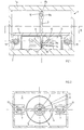
- the housing 1 has an upper carrier 1a, which is a magnet 8b carries, and a lower support 2, the carries a stator 5 and two pairs of Helmholtz coils 11.
- the stator 5 has an inverted frustoconical shape Recess for receiving a measurement sample 12 on the Base area is a ball 10, the rotor 6 in the Point 14 is touched.
- the rotor 6 is located at the lower end of a vertical measuring shaft 3 and contains a magnet 9a, which preferably together with one Similar magnets 9b centered in the stator 5, the ball 10.
- a Magnet 8a At the upper end of the measuring shaft 3 is a Magnet 8a, which cooperates with the stationary Magnets 8b centered the measuring shaft 3.
- the measuring shaft 3 is guided in an unstable manner not stored rigidly. The centering is done without contact with the help of the small high-performance permanent magnets 8a, 8b in a simple way.
- the only (fraught) mechanical support point 14 lies in the zero point of rotation, the Frictional force therefore has practically no lever arm and is therefore negligibly small.
- the measuring shaft 3 is relatively short (a few cm to a maximum of 20 cm) and lies with its lower end directly in the test sample 12. It rests centrally (as a mechanical support point) symmetrical on the small ball 10 (diameter about 0.5 to 2 mm), which is in the test sample 12. This ball 10 thereby determines the width of the measuring gap in a clear way and is through the little magnets 9a, 9b, which correspond to the ball size, exactly centered.
- the measuring shaft 3 is floating at its upper end, however, it carries the strong permanent magnet at this end or rotor magnets 8a (NeFeB or SmCo or the like as Magnetic material), which is arranged centrically symmetrically and is axially polarized.
- the stator magnet 8b As a counter magnet, which is based on attraction is poled.
- the stator magnet 8b pulls the measuring shaft 3 smoothly in the axial direction so that the measuring shaft 3 is aligned exactly vertically.
- the storage of the Measuring shaft 3 on the ball 10 is due to the axial tensile force of the upper pair of magnets 8a, 8b simultaneously relieved in weight, so that the measuring shaft 3 practically smoothly on the selective ball bearing in the Measurement sample 12 is at rest.
- the viscosity of the test sample 12 causes a further rotationally symmetrical stabilization of the Measuring shaft 3 during the oscillating (or rotating) Movement in the measuring phase.
- This arrangement is very easy to manufacture and very effective.
- the magnets the size of a few millimeters up to a maximum of 20 mm cost little.
- the system is very easy to use due to the easy dismantling, a bending of the measuring shaft 3 with certainty is to be excluded.
- the drive can also be easily getting produced.
- the oscillation is only a few Angular degrees, which with a radius of the drive system of z. B. 50 mm of a path amplitude of only a few millimeters equivalent.
- the drive system consists of a cross member 4, which is passed exactly horizontally through the measuring shaft 3 is.
- two permanent magnets 7 are attached rotationally symmetrically, which are mechanically arranged so that they are exactly in the plane of the test sample 12. Thereby it is ensured that the measuring shaft 3 due to the viscous The resistance of the test sample 12 is not during the measuring operation auspendelt.
- the two permanent magnets 7 have their poles in the direction of movement, i.e. in the direction the extent of the rotational movement.
- the magnets 7 are located within the effective space two pairs of Helmholtz coils 11.
- a Helmholtz coil has a very homogeneous between the two individual coils magnetic flux density, regardless of the exact position in the knitting space. Depending on the polarity of the coil current and its current strength, the magnet 7 is therefore more or pulled less forcefully in the appropriate direction. If an AC voltage is applied to the coil 11, then creates the desired oscillation of the measuring shaft 3 in rotationally symmetrical direction.
- Lever arm distance of the drive magnets 7 from the axis of rotation the measuring shaft 3
- the force amplitude adjusted the viscosity measuring range or the sample geometry become.
- moving coil systems can also be used (Principle of dynamic loudspeaker) or at simpler measuring tasks for single oscillation too Permanent magnet systems that are manually in the effective range of the two drive magnets are swiveled in, use Find.
- the drive AC voltage can be used with commercially available tunable frequency generators in common curve shapes (Rectangle, triangle, sine, pulse, etc.) or with a PC or with feedback vibrators be generated.
- the force amplitudes can be determined relatively easily be strictly related to the amperage of the drive AC voltage correlate. You can calculate them record or using calibration methods based on known Calibration measurement samples or indirectly via a force measurement (e.g. experimentally using scales).
- the path amplitudes can also be done with little Effort via optoelectronic sensors or magnetic field sensors (e.g. Hall probe). With the latter method the magnetic field influence of the drive magnet directly cause the measuring signal of the Hall probe, a special one low construction effort is made possible.
- Such a detection of the path amplitude is the circuit based on Figure 3.
- the movement of the drive magnet 7 changes the magnetic field between the coils 11 and this magnetic field change is from the Hall probe 20th detected.
- an appropriate instrument amplifier 21 amplified voltage signal is used as a path signal the data processing system on the one hand and a DC voltage amplifier 22 with variable gain on the other hand fed.
- this DC voltage amplifier 22nd the maximum path amplitude can be set.
- That so amplified signal is fed to a Schmitt trigger 23 and causes - if the trigger threshold is exceeded becomes - an output signal, which via an integrator 24th with triangular output voltage and possibly one Triangle-sine converter 25 and an output stage 26 ( ⁇ 10 V, 1-100 mA) initiates a control signal that on the one hand as a force signal for data processing and on the other hand fed to the control 27 of the coils 11 becomes.
- This circuit causes that when the maximum path amplitude through the drive magnet 7 that Magnetic field between the coils 11 is reversed, so that the drive magnet 7 between the two coils 11 out and swings here.
- About the data processing system can the from the path signals and the force signals plastic and elastic properties of the test sample be determined.
- the processing of the measuring signals is coordinated the desired measurement target either analog, digital or combined. Recommended for higher demands in any case, the very reasonably priced PC-supported measurement data acquisition.
- the measurement series can Force, path, phase, frequency or temperature controlled be performed.
- a very simple measuring operation can be carried out in a controlled manner.
- a desired path amplitude is set beforehand.
- a trigger circuit is used when the Target displacement amplitude of the supply current of the drive coils reversed polarity, so that a (feedback) oscillation arises.
- the higher the viscosity of the sample the more the period of the individual vibration becomes longer and the slower the oscillation frequency.
- the period can be very simple and also inexpensive Determine and be displayed in ways. In this Operating mode can very easily be temperature viscosity curves be determined.
Landscapes
- Physics & Mathematics (AREA)
- Health & Medical Sciences (AREA)
- Life Sciences & Earth Sciences (AREA)
- Chemical & Material Sciences (AREA)
- Analytical Chemistry (AREA)
- Biochemistry (AREA)
- General Health & Medical Sciences (AREA)
- General Physics & Mathematics (AREA)
- Immunology (AREA)
- Pathology (AREA)
- Measurement Of Length, Angles, Or The Like Using Electric Or Magnetic Means (AREA)
- Investigating Or Analyzing Materials By The Use Of Magnetic Means (AREA)
- Investigating Or Analysing Biological Materials (AREA)
Description
- Fig. 1
- zeigt einen Vertikalschnitt durch ein Viskosimeter,
- Fig. 2
- einen Horizontalschnitt entlang der Linie II-II in Fig. 1 und
- Fig. 3
- eine mögliche Meßschaltung in schematischer Darstellung.
Claims (8)
- Rotationsviskosimeter mit vorzugsweise oszillierendem Meßprinzip enthaltend eine über einen Antrieb um ihre Längsachse drehbare Meßwelle, die an einem ihrer Enden einen Rotor aufweist, und einen dem Rotor gegenüberliegenden Stator, wobei der Rotor auf einer zwischen Rotor und Stator befindlichen Kugel gelagert und wobei ein zwischen dem Rotor und dem Stator gebildeter Raum zur Aufnahme einer Meßprobe bestimmt ist, dadurch gekennzeichnet, daß die Kugel (10) die einander zugewandten Oberflächen des Rotors (6) und des Stators (5) punktförmig berührt.
- Rotationsviskosimeter nach Anspruch 1, dadurch gekennzeichnet, daß die Kugel (10) aus magnetisierbarem Material ist und von im Rotor (6) und im Stator (5) vorgesehenen und zur Längsachse der Meßwelle (3) rotationssymmetrischen Magneten (9a, 9b) zentriert wird.
- Rotationsviskosimeter nach Anspruch 1 oder 2, dadurch gekennzeichnet, daß die Meßwelle (3) an ihrem dem Rotor (6) abgewandten Ende einen weiteren zu ihrer Längsachse rotationssymmetrischen und axial gepolten Magneten (8a) aufweist, der einen in einem ortsfesten Träger (1) angeordneten, ebenfalls zur Längsachse der Meßwelle (3) rotationssymmetrischen und axial gepolten Gegenmagneten (8b) gegenüberliegt, wobei die beiden Magneten (8a, 8b) einander anziehend gepolt sind und zwischen dem Ende der Meßwelle (3) und dem Träger (1) ein Spalt (15) vorhanden ist.
- Rotationsviskosimeter nach einem der vorhergehenden Ansprüche, dadurch gekennzeichnet, daß die Meßwelle (3) mit einem normal zu ihrer Längsachse ausgerichteten Dreharm (4) verbunden ist, der an seinen beiden Armen rotationssymmetrisch Antriebsmagnete (7) trägt, die in Rotationsrichtung gepolt sind und sich im Wirkungsbereich eines ortsfesten Magnetsystems (11) befinden.
- Rotationsviskosimeter nach Anspruch 4, dadurch gekennzeichnet, daß sich die Antriebsmagnete (7) auf der Höhe der Meßprobe (12) befinden.
- Rotationsviskosimeter nach Anspruch 4 oder 5, dadurch gekennzeichnet, daß das Magnetsystem (11) aus zwei Helmholtzspulen- oder Tauchspulenpaaren besteht.
- Rotationsviskosimeter nach Anspruch 6, dadurch gekennzeichnet, daß die Spulen (11) mit Wechselspannung versorgt werden.
- Rotationsviskosimeter nach Anspruch 4 oder 5, dadurch gekennzeichnet, daß das Magnetsystem (11) ein Permanentmagnetsystem ist, das manuell in die Wirkposition bringbar ist.
Applications Claiming Priority (3)
| Application Number | Priority Date | Filing Date | Title |
|---|---|---|---|
| AT86496A AT404301B (de) | 1996-05-15 | 1996-05-15 | Rotationsviskosimeter |
| AT864/96 | 1996-05-15 | ||
| AT86496 | 1996-05-15 |
Publications (3)
| Publication Number | Publication Date |
|---|---|
| EP0807808A2 EP0807808A2 (de) | 1997-11-19 |
| EP0807808A3 EP0807808A3 (de) | 1998-07-08 |
| EP0807808B1 true EP0807808B1 (de) | 2002-01-02 |
Family
ID=3501577
Family Applications (1)
| Application Number | Title | Priority Date | Filing Date |
|---|---|---|---|
| EP19970107415 Expired - Lifetime EP0807808B1 (de) | 1996-05-15 | 1997-05-06 | Viskosimeter |
Country Status (3)
| Country | Link |
|---|---|
| EP (1) | EP0807808B1 (de) |
| AT (1) | AT404301B (de) |
| DE (1) | DE59705932D1 (de) |
Cited By (1)
| Publication number | Priority date | Publication date | Assignee | Title |
|---|---|---|---|---|
| DE102007040563B4 (de) * | 2007-08-28 | 2014-05-28 | Continental Automotive Gmbh | Rotationsviskosimeter |
Family Cites Families (7)
| Publication number | Priority date | Publication date | Assignee | Title |
|---|---|---|---|---|
| US4045999A (en) * | 1976-11-05 | 1977-09-06 | Sydney Hospital | Rotational viscometers |
| SU920467A1 (ru) * | 1980-07-07 | 1982-04-15 | Уфимский авиационный институт им.Орджоникидзе | Вискозиметр |
| DD221276A1 (de) * | 1984-02-06 | 1985-04-17 | Medizin Labortechnik Veb K | Vorrichtung zur fuehrung und lagerung rheologischer messsysteme, insbesondere rotationsrheometer |
| SU1160277A1 (ru) * | 1984-03-27 | 1985-06-07 | Sp K Byuro Biolog Priborostr | Устройство для вывода информации |
| DE3423579C1 (de) * | 1984-06-27 | 1985-08-22 | Nukem Gmbh, 6450 Hanau | Rotationsviskosimeter |
| FR2572527B1 (fr) * | 1984-10-30 | 1987-12-11 | Bertin & Cie | Procede et dispositif de mesure de caracteristiques rheologiques d'un fluide, en particulier d'un fluide biologique tel que le sang |
| DD252438A1 (de) * | 1986-08-08 | 1987-12-16 | Medizin Labortechnik Veb K | Rotationsviskosimeter |
-
1996
- 1996-05-15 AT AT86496A patent/AT404301B/de not_active IP Right Cessation
-
1997
- 1997-05-06 DE DE59705932T patent/DE59705932D1/de not_active Expired - Fee Related
- 1997-05-06 EP EP19970107415 patent/EP0807808B1/de not_active Expired - Lifetime
Cited By (1)
| Publication number | Priority date | Publication date | Assignee | Title |
|---|---|---|---|---|
| DE102007040563B4 (de) * | 2007-08-28 | 2014-05-28 | Continental Automotive Gmbh | Rotationsviskosimeter |
Also Published As
| Publication number | Publication date |
|---|---|
| EP0807808A3 (de) | 1998-07-08 |
| DE59705932D1 (de) | 2002-02-07 |
| EP0807808A2 (de) | 1997-11-19 |
| ATA86496A (de) | 1998-02-15 |
| AT404301B (de) | 1998-10-27 |
Similar Documents
| Publication | Publication Date | Title |
|---|---|---|
| DE10047793B4 (de) | Rotationsrheometer | |
| DE69825747T2 (de) | Lagervorrichtung | |
| AT508706B1 (de) | Verfahren zur untersuchung von proben mit einem rheometer sowie rheometer | |
| EP0506605A1 (de) | Einrichtung zum Auffinden magnetisierbaren Materials in Bauwerken | |
| DE112016000875T5 (de) | Hall-Messsystem mit rotierendem Magnetfeld | |
| CH671634A5 (de) | ||
| EP1926971B1 (de) | Verfahren und anordnung zur berührungslosen inspektion bewegter elektrisch leitfähiger substanzen | |
| EP1009972B1 (de) | Vorrichtung zum erfassen rotatorischer bewegungen | |
| EP1556665B1 (de) | Tastkopf mit magnet und hallelement für den einsatz in einem koordinatenmessgerät | |
| EP0100429A2 (de) | Messumformer | |
| DE102018213674A1 (de) | Sensorzusammenbau zur Koordinatenmessung an einem Werkstück | |
| EP0807808B1 (de) | Viskosimeter | |
| DE3111060C2 (de) | ||
| DE2158715B2 (de) | Geraet zur magnetischen gasanalyse | |
| DE10043302A1 (de) | Magnetlagerung | |
| DE102013219287A1 (de) | Materialprüfgerät und Prüfverfahren zur zerstörungsfreien Prüfung von Eigenschaften eines Prüflings | |
| DE1573837C3 (de) | Prüfvorrichtung zur zerstörungsfreien Werkstoffprüfung magnetisierbarer Materialien | |
| WO1986000408A1 (fr) | Appareil pour la mesure des proprietes rheologiques | |
| AT1156U2 (de) | Rotationsviskosimeter | |
| DE10209350B4 (de) | Rheometer | |
| EP1820003B1 (de) | Verfahren und vorrichtung zur untersuchung der materialeigenschaften mindestens einer von zwei gegeneinander bewegter proben | |
| DE3337893A1 (de) | Anordnung zum pruefen eines ferromagnetischen rohres auf fehler | |
| DE10060189A1 (de) | Kapazitätsabstandssensor für Vorrichtung zur Bestimmung einer Oberflächenkonfiguration | |
| DE3544967C2 (de) | ||
| EP1098335B1 (de) | Kraftschlussdetektor mit Drehmomentschalter |
Legal Events
| Date | Code | Title | Description |
|---|---|---|---|
| PUAI | Public reference made under article 153(3) epc to a published international application that has entered the european phase |
Free format text: ORIGINAL CODE: 0009012 |
|
| AK | Designated contracting states |
Kind code of ref document: A2 Designated state(s): DE FR GB IT |
|
| PUAL | Search report despatched |
Free format text: ORIGINAL CODE: 0009013 |
|
| AK | Designated contracting states |
Kind code of ref document: A3 Designated state(s): DE FR GB IT |
|
| 17P | Request for examination filed |
Effective date: 19990108 |
|
| 17Q | First examination report despatched |
Effective date: 19990909 |
|
| RAP1 | Party data changed (applicant data changed or rights of an application transferred) |
Owner name: OESTERREICHISCHE VIALIT GESELLSCHAFT MBH |
|
| GRAG | Despatch of communication of intention to grant |
Free format text: ORIGINAL CODE: EPIDOS AGRA |
|
| GRAG | Despatch of communication of intention to grant |
Free format text: ORIGINAL CODE: EPIDOS AGRA |
|
| GRAH | Despatch of communication of intention to grant a patent |
Free format text: ORIGINAL CODE: EPIDOS IGRA |
|
| GRAH | Despatch of communication of intention to grant a patent |
Free format text: ORIGINAL CODE: EPIDOS IGRA |
|
| GRAA | (expected) grant |
Free format text: ORIGINAL CODE: 0009210 |
|
| REG | Reference to a national code |
Ref country code: GB Ref legal event code: IF02 |
|
| AK | Designated contracting states |
Kind code of ref document: B1 Designated state(s): DE FR GB IT |
|
| REF | Corresponds to: |
Ref document number: 59705932 Country of ref document: DE Date of ref document: 20020207 |
|
| GBT | Gb: translation of ep patent filed (gb section 77(6)(a)/1977) |
Effective date: 20020326 |
|
| ET | Fr: translation filed | ||
| PLBE | No opposition filed within time limit |
Free format text: ORIGINAL CODE: 0009261 |
|
| STAA | Information on the status of an ep patent application or granted ep patent |
Free format text: STATUS: NO OPPOSITION FILED WITHIN TIME LIMIT |
|
| 26N | No opposition filed | ||
| PGFP | Annual fee paid to national office [announced via postgrant information from national office to epo] |
Ref country code: GB Payment date: 20040423 Year of fee payment: 8 |
|
| PGFP | Annual fee paid to national office [announced via postgrant information from national office to epo] |
Ref country code: FR Payment date: 20040428 Year of fee payment: 8 |
|
| PGFP | Annual fee paid to national office [announced via postgrant information from national office to epo] |
Ref country code: DE Payment date: 20040724 Year of fee payment: 8 |
|
| PG25 | Lapsed in a contracting state [announced via postgrant information from national office to epo] |
Ref country code: IT Free format text: LAPSE BECAUSE OF NON-PAYMENT OF DUE FEES;WARNING: LAPSES OF ITALIAN PATENTS WITH EFFECTIVE DATE BEFORE 2007 MAY HAVE OCCURRED AT ANY TIME BEFORE 2007. THE CORRECT EFFECTIVE DATE MAY BE DIFFERENT FROM THE ONE RECORDED. Effective date: 20050506 Ref country code: GB Free format text: LAPSE BECAUSE OF NON-PAYMENT OF DUE FEES Effective date: 20050506 |
|
| PG25 | Lapsed in a contracting state [announced via postgrant information from national office to epo] |
Ref country code: DE Free format text: LAPSE BECAUSE OF NON-PAYMENT OF DUE FEES Effective date: 20051201 |
|
| GBPC | Gb: european patent ceased through non-payment of renewal fee |
Effective date: 20050506 |
|
| PG25 | Lapsed in a contracting state [announced via postgrant information from national office to epo] |
Ref country code: FR Free format text: LAPSE BECAUSE OF NON-PAYMENT OF DUE FEES Effective date: 20060131 |
|
| REG | Reference to a national code |
Ref country code: FR Ref legal event code: ST Effective date: 20060131 |